Your browser does not fully support modern features. Please upgrade for a smoother experience.
Please note this is a comparison between Version 2 by Mona Zou and Version 3 by Mona Zou.
Metal selenide materials have attracted attention due to their wide application prospects. In this family of materials, FeSe is particularly studied since it is both a semiconductor used in solar cells and a superconductor with a critical transition temperature, Tc, of 8 K. For any envisaged application, the possibility of preparing large-area FeSe thin films at low cost is extremely appealing, and one possible technique suitable for this purpose is electrodeposition. Several groups have reported successful electrodeposition of FeSe, but the investigated systems are different in many aspects, and the results are difficult to compare.
- iron selenide
- electrodeposition
- thin films
1. Introduction
Transition metal chalcogenides have been widely studied because of the peculiar electronic properties that make them interesting for a large variety of applications, for example, as anode materials for sodium-ion batteries, cathode materials for lithium-air batteries [1][2], photo-absorbers for photovoltaics [3], and non-linear optical materials for bioimaging [4]. More recently, their relevant role as electrocatalysts in oxygen evolution reactions (OERs), hydrogen evolution reactions (HERs), and overall water splitting was demonstrated [5][6][7][8]. In the case of FeSe, much attention was raised because of its potential application as a solar cell absorber, and even more after the discovery of superconductivity in this family of compounds. The search for new superconducting materials fuelled research on this topic, and much effort is still being spent on the fabrication of FeSe thin films for a variety of applications, such as the design of a conductor [9][10][11][12][13] or its use as a low-resistivity coating in cavities for axions detection [14]. Several techniques are successfully employed for the growth of FeSe films, such as molecular beam epitaxy (MBE), pulsed laser deposition (PLD), and chemical vapor deposition (CVD). A detailed review of the fabrication methods and applications for FeSe can be found in [15]. These methods have been essential for the study of the properties of the material but are not suitable for the growth of larger-scale samples, for whatever application, or for the foreseen industrial scale-up. Electrodeposition has several advantages over the aforementioned thin-film deposition techniques. As an electric (and not a thermal) process, it can be carried out at room temperature (or close) and at ambient pressure. It can provide large, thick, and uniform films of complex, curved shapes, and it can easily be scaled up due to the inexpensive equipment and standard laboratory conditions required for the process. On the other hand, the crystalline quality and the microstructure of the deposit are not comparable to those obtained via other techniques such as MBE, PLD, or CVD. However, its potential led several authors to investigate the possibility of growing FeSe via electrodeposition, with the aim of applying it to large-scale applications such as dye-sensitized solar cells [16] or superconducting tapes [17][18][19].
2. FeSe Structure
Fe–Se is a complex system that can exist in many different phases corresponding to different structures and stoichiometries, as reported in the phase diagram in [20]. However, FeSe mainly exhibits two crystalline forms: tetragonal PbO-like phase (P4/nmm space group, b in the phase diagram in Figure 1 (Upper panel)) and hexagonal NiAs-type phase (P63/mmc space group, g in the phase diagram in Figure 1 (Upper panel)) [21]. Both structures show alternate Fe/Se layers, but in the tetragonal phase, tetrahedral coordination is found between Fe and Se, whereas in the hexagonal phase, Fe coordinates Se octahedrally. Distinct bond regimes can be found in both structures: within the Fe–Se layer, the bonding regime is of the mixed metallic-covalent type, with Fe–Fe metallic bonds and Fe–Se covalent bonds. Instead, in the c-axis direction, the main interaction is through van der Waals forces [22][23]. The X-ray patterns and structures of these two phases are shown in Figure 1. The phase stability of these structures is limited to a very narrow region of the Fe–Se phase diagram [20], and the interconversion of one phase into the other occurs around 300 °C and/or high pressure. The properties of this material are strongly dependent on its crystalline structure and microstructure; for example, the hexagonal FeSe phase (a = 3.519 Å; c = 5.684 Å) is a ferrimagnet up to approximately 400 K, whereas tetragonal FeSe (a = 3.689 Å; c = 5.854 Å) undergoes a structural transition to an orthorhombic FeSe phase (space group: Cmma) below 90–100 K and shows a superconducting transition temperature at Tc ≈ 8 K, as reported by [24][25]. Superconductivity is also strongly dependent on the lattice parameter, on the Fe–Se distance, and, consequently, on every factor influencing those parameters, such as temperature, strain, intercalation, pressure, and atom substitutions [26]. On the other hand, crystallite size also plays a major role in tuning electrical properties such as band gap, absorption coefficient, absorbance/transmittance, et cetera [21][27][28][29][30]. These dependencies need to be taken into account when planning the use and preparation of FeSe for a specific application.
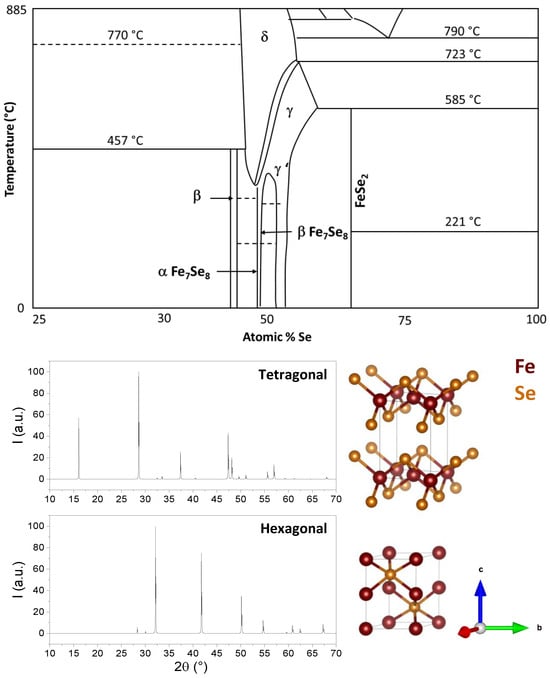
Figure 1. (Upper panel): Portion of interest of the phase diagram of the Fe-Se system. Data from [20]. (Lower panel): X-ray simulated diffraction patterns crystal structures of tetragonal and hexagonal FeSe.
3. Thermodynamic Analysis
Electrochemical deposition (or electrodeposition) is a simple and versatile chemical solution deposition method based on redox reactions happening in an electrochemical cell [31][32]. An electrochemical cell is made of a vessel containing an electrolytic bath with a working electrode, a counter electrode, and a reference electrode. The reference electrode is needed because it provides the stable ground voltage needed to accurately measure the electrochemical potentials by providing an isolated and stable chemical reaction that produces a known voltage. The reference electrode is placed very close to the working electrode in order to determine its potential against the stable reference electrode. The fundamental reference is the standard hydrogen electrode (SHE), for which the equilibrium between H+ and H2 gas is defined as zero. Standard electrode potentials (equilibrium potentials of an electrode reaction), E0, are expressed relative to SHE and can be found tabulated. In practice, other, more convenient reference electrodes are in use, for example, silver chloride (Ag/AgCl) or saturated calomel (Hg2Cl2). The chemical reactions at the electrode surfaces involve electron and ion transfer and are ideally controlled by the electrode potential. The voltage and current flowing between the electrodes control the chemical processes, and the working electrode usually acts as a substrate.
In principle, to define the optimal conditions for electrodeposition, the determination and analysis of the potential–pH diagram, also known as the Pourbaix diagram, is useful. Below, the thermodynamic analysis, as presented in [33], is reported. Symbols are explicated in Table 1. now consider a hypothetical system where the redox reactions occurring in the solution are expressed generically as

Table 1. List of symbols.
| a, b, c, n, m | Stoichiometric Number | |
 |
Standard Gibbs free energy at 298 K | kJ mol−1 |
 |
Standard molar reactive Gibbs free energy | kJ mol−1 |
 |
Molar reactive Gibbs free energy | kJ mol−1 |
| R | Molar gas constant | 8.314 J K−1 mol−1 at 298 K |
| T | Temperature | K |
 |
Activity of substance X | |
| F | Faraday’s constant | 96,485 C mol−1 |
 |
Standard electrode potential | V |
| E | Electrode Potential | V |
When pressure and temperature are constant, the molar Gibbs energy change for the reaction can be written as

If 𝑎H2O = 1, −lgaH+ = pH, combining with ∆r𝐺m=−n𝐹𝐸 and ∆r𝐺∗m=−n𝐹𝐸∗, it can be obtained

That can be further simplified for reactions not involving electrons (n = 0) in

or, for reaction not involving H+/OH− (m = 0), in

If both electrons and H+/OH− are involved, there have

From these general equations and thermodynamic data available, it is possible to draw the potential–pH diagram for the general metal selenide system Me–Se–H2O (see Figure 2), where, for every reaction, the ∆G∗298 can be calculated by ∆G∗298=∑∆G∗298(products)−∑∆G∗298(reactants). The reactions of interest are:
Me2+ + Se + 2e− = MeSe
MeSe + 2H+ = Me2+ + H2Se
MeSe + 2H+ + 2e− = Me + H2Se
MeSe + H+ + 2e− = Me + HSe
Me2+ + H2SeO3 + 4H+ + 6e− = MeSe + 3H2O
Me2+ + HSeO3− + 5H+ + 6e− = MeSe + 3H2O
Me2+ + SeO32− + 6H+ + 6e− = MeSe + 3H2O
Me(OH)2 + SeO32− + 8H+ + 6e− = MeSe + 5H2O
Me2+ + 2e− = Me
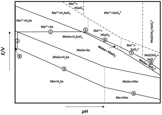
Figure 2. General E–pH diagram for the Me–Se–H2O system. Adapted from [33].
The thermodynamic data useful for the derivation of the E–pH diagram for FeSe can be found in Table 2. Once the temperature and concentration of species in solution are defined, a diagram such as that in Figure 2 can be derived. From this diagram, it can be infered that the stability of MeSe is defined by lines 4-3-2-1-5-6-7-8, and this area can extend to a wide range of potential and pH. Moreover, the redox potential for the formation of MeSe is higher than that of the reduction of Me2+ to pure metal, which means that Me2+ metal ions are more easily deposited as MeSe than pure metal. This behavior is due to the release of Gibbs free energy during the formation of metal selenides, which will result in a positive shift in deposition potential for MeSe. This process is known as the Kroger mechanism or induced underpotential deposition, and it is often exploited in the electrodeposition of metal selenides [34].
Table 2. Thermodynamic data of substances of interest for the Fe–Se–H2O system (from [33]).
| Substance |  (kJ/mol) (kJ/mol) |
Substance |  (kJ/mol) (kJ/mol) |
|---|---|---|---|
| (kJ/mol) | |||
| FeSe | −87.533 | Fe | −8.31 |
| Fe2+ | −35.585 | Fe3+ | 64.332 |
| Se | −12.592 | HSe− | −14.035 |
| H2Se (g) | −35.950 | SeO32− | −525.577 |
| H2SeO3 | −569.233 | HSeO3− | −560.894 |
| Potential–pH formulas for FeSe0.96 | |||
| Fe2+ + 2e− = Fe | E = −0.5985 | ||
| Fe2+ + 0.96Se + 2e− = FeSe0.96 | E = −0.249 | ||
| FeSe0.96 + 1.92H+ + 1.92e− = Fe + 0.96H2Se | E = −0.278 − 0.059pH | ||
| FeSe0.96 + 0.96H+ + 1.92e− = Fe + 0.96HSe− | E = −0.424 − 0.030pH | ||
| Fe2+ + 0.96SeO32− +5.76H+ + 5.84e− = FeSe0.96 + 2.88H2O | E = 0.430 − 0.058pH | ||
Notwithstanding the availability of thermodynamic data in the literature, it becomes extremely complicated to adapt the theoretical model to real experiments due to a larger number of variables to consider, mainly the presence of other species in the solution, such as the electrolyte and the metal and selenium counter ions, that might be involved in a series of collateral reactions or the presence of the working electrode that might not behave just as an inert surface. This leads to the necessity to approach the system in a more practical way, which confines thermodynamic analysis to a precious tool to unravel the complexity of experimental data rather than use it as a predictive method for experimental design.
4. Electrodeposition of FeSe
Although electrodeposition is restricted to a number of elementary metals, it has attracted great interest in the metallurgy of alloys. The simultaneous deposition of more than one elemental precursor in the same electrolyte in order to create an alloy or a chemical compound is called co-deposition. It is a widely employed technique for the fabrication of thin films [35] of compounds such as sulfides, tellurides, and selenides (PbSe [36], NiSe [37], ZnSe [38], or CdSe [39]).
The chemical composition of co-deposited films can be controlled via the chemical composition of the solution and the galvanic potential between the electrodes. The electrodeposition of alloys relies on the similar reduction potential of the components. The co-deposition of a metal and a non-metal, instead, is, in principle, a more challenging issue because of the largely different standard (equilibrium) potentials of the metal and non-metal atoms. For Fe and Se, the potential difference E0 = Emetal − Enonmetal is 1.225 V. Therefore, preferential plating of the more noble element (Se in this case) is expected to occur, and its more positive potential inhibits FeSe alloy formation. Fortunately, one can overcome the difference in potential [40]. A shift in the deposition potentials of the constituents is achieved by changing the concentration or activity of the ions in the solution, for example, by using complexants or additives. In fact, co-deposition has been a successful methodology for forming II ± VI compounds. Stoichiometry is maintained by having the more noble element as the limiting reagent and choosing the potential where the less noble element will underpotentially deposit only on the more noble element [34].
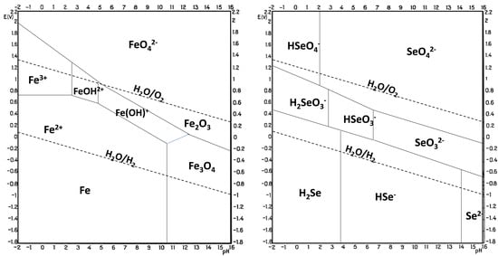
The electrodeposition of metal selenides is generally performed under acidic conditions at pH 1–3. This pH range is defined by the stability of the chemical species involved, and this information can be derived from Pourbaix diagrams (Figure 3 [41]) that describe the stability zones for an element as a function of pH and potential. Comparing Pourbaix diagrams for a compound’s constituent elements gives an indication of the probability of forming a stable compound electrochemically and the potential and pH that might be used. The overlap of the conditions where both elements exist in their elemental state is a good indication of where to start. In more detail, in the FeSe case, the pH is limited by the hydrolysis of FeSe and/or hydrogen evolution at low pH values, not to mention the necessity to reduce Se(II) or Se(IV), a process that consumes large amounts of H+ and that would be hindered at higher pH [33]. The increase in pH of the deposition solution also results in the acceleration of Fe2+ oxidation and further precipitation of Fe(OH)3, as well as slowing down the electroreduction of selenium species. To complicate the matter further, no overlap of the stability zone is found for Fe and Se [42]; therefore, the formation of FeSe via solid-state reaction seems unlikely; instead, it might expect a reaction of the more noble element (Se) that, after reduction, reacts with the less noble metal ions in the solution and precipitates on the electrode. However, the mechanism of cathodic electrodeposition of selenides from Fe and Se precursors in solution is not well understood. A hypothesis involves a direct reaction between Fe2+ and Se2− in the solution bulk, followed by FeSe precipitation onto the electrode surface [43][44]. The redox reaction for the formation of FeSe is
Fe2+ + Se + 2e− → FeSe
where Se is first reduced to Se2− and then reacts with iron(II) ions. Another interpretation sees the reduction process and solid-state reactions in both Fe and Se after plating.
Figure 3. Pourbaix diagram for Fe (left) and Se (right) at 25 °C and 1 atm. Adapted from [41].
The insufficient understanding of the electrochemical reactions occurring in the deposition solution, along with conflicting data on the reaction mechanism, hinders the optimization of electrodeposition conditions. An educated guess on the reactions occurring at the working electrode requires parallelism with the closest iron chalcogenide, FeS2, whose electrodeposition was suggested to happen in two steps: first the reduction and adsorption of sulfur on the electrode, and then the reaction with Fe2+ that reaches the interface through the double layer and precipitates ad FeSx on the electrode [45]. Therefore, it can be hypothesized as a similar mechanism for FeSe, such as:
Se + 2e− → (Se2−)ads
(Se2−)ads → FeSe
While on the counter electrode, oxygen evolution is observed (supposing an aqueous medium). However, due to the unstable precursor used, the mechanism, in practice, can be far more complicated than the previous hypothesis. Iron(II) salts, which are preferred since the Fe oxidation state is the one required for FeSe formation, are highly unstable [46] and often oxidized during storage or inside the precursor solution if not properly degassed. Moreover, precipitation of species after oxidation occurs, which means not having complete control of the real amount of Fe(II) in the solution. Fe(III) salts are more reliable from this point of view and were also employed by some groups [47], but the electrochemistry of the system is complicated by the necessity of controlling the reduction of Fe(III). On the other hand, Se shows a very complicated electrochemistry with the existence of different solution species and their reduction products in acid media [48]. Depending on the solution pH and temperature, the nature of the dissolved Se species varies. When the Se precursor is dissolved in water, either SeO2, H2SeO3, or the respective salt Na2SeO3, it can participate in equilibrium reactions such as
H2SeO3 ⇌ HSeO3− + H+ (pK = 2.72)
HSeO3− ⇌ SeO3− + H+ (pK = 8.32)
If the conditions are met, the species in solution can be part of several redox reactions, such as
SeO42− + 4H+ + 2e− ⇌ H2SeO3 + H2O 1.150 V
SeO42− + H2O + 2e− ⇌ SeO32− + 2OH− 0.050 V
H2SeO3 + 4H+ + 4e− ⇌ Se + 3H2O 0.740 V
SeO32− + 3H2O + 4e− ⇌ Se + 6OH− −0.366 V
HSeO3− + 4e− + 5H+ ⇌ Se + 3H2O 0.778 V
H2SeO3 + 6H+ + 6e− ⇌ H2Se + 3H2O 0.360 V
SeO32− + 6H+ + 6e− ⇌ Se2− + 3H2O 0.276 V
HSeO3− + 6e− + 7H+ ⇌ H2Se + 3H2O 0.386 V
Se + 2H+ + 2e− ⇌ H2Se− −0.369 V
Se + 2e2 ⇌ Se2− −0.920 V
Moreover, because of the multiple oxidation states, Se can engage in numerous self-exchange reactions: Se(VI)/Se(IV), Se(IV)/Se(0), Se(IV)/Se(-II), Se(0)/Se(-II), et cetera. The presence of so many species at the same time makes the identification of the FeSe deposition potential and the selective promotion of this reaction a complicated matter.
The ideal voltage necessary for the desired reaction of FeSe deposition to occur is often experimentally identified via cyclic voltammetry (CV). In CV, the current (or current density J) is measured as a function of the applied potential, which is swept in the range of interest in a direct and reverse scan at constant speed. The voltammogram will then show sudden increases in current in correspondence with redox reactions occurring in the electrolyte. The identification of these reactions is not always straightforward, but in general, it is possible to discern the required potential for deposition of the desired phase. To make the identification process easier, the study of the CV of the single reactants in the conditions selected for deposition can be helpful, as can a comparison with theoretical data available in the literature. It should be considered, though, that this value may change when experimental conditions are changed. Therefore, direct comparison between the available data is tricky and should be approached accordingly. For example, some experimental conditions influencing the electrodeposition process and potential are:
-
The electrolyte: i.e., the precursors and the solution. Different precursors give different results even if the element to be deposited is in the same oxidation state. Solubility, solvation effects, and other phenomena indirectly influence the reactions in the solution/on the electrode.
-
Electrode materials, working electrode potential (with respect to the reference electrode); even if the working electrode (substrate) is non-reacting, different materials will give different working potentials and, therefore, different results.
-
The pH of the solution influences the stability of the electrodes, the precursor salts, the conductivity of the solution, et cetera.
-
Additives/complexing agents: used to increase the solubility of precursors, they influence the adsorption of metal ions at the substrate surface, film nucleation, and growth.
-
The operation temperature (usually between room temperature and T < 100 °C)
References
- Zhang, K.; Hu, Z.; Liu, X.; Tao, Z.; Chen, J. FeSe2 microspheres as a high-performance anode material for Na-ion batteries. Adv. Mater. 2015, 27, 3305–3309.
- Yoo, H.; Lee, G.H.; Kim, D.W. FeSe hollow spheroids as electrocatalysts for high-rate Li–O2 battery cathodes. J. Alloys Compd. 2021, 856, 158269.
- Wang, W.; Pan, X.; Liu, W.; Zhang, B.; Chen, H.; Fang, X.; Yao, J.; Dai, S. FeSe2 films with controllable morphologies as efficient counter electrodes for dye-sensitized solar cells. Chem. Commun. 2014, 50, 2618–2620.
- Kwon, J.; Jun, S.W.; Choi, S.I.; Mao, X.; Kim, J.; Koh, E.K.; Kim, Y.H.; Kim, S.K.; Hwang, D.Y.; Kim, C.S.; et al. FeSe quantum dots for in vivo multiphoton biomedical imaging. Sci. Adv. 2019, 5, eaay0044.
- Chanda, D.; Tufa, R.A.; Birdja, Y.Y.; Basu, S.; Liu, S. Hydrothermally/electrochemically decorated FeSe on Ni-foam electrode: An efficient bifunctional electrocatalysts for overall water splitting in an alkaline medium. Int. J. Hydrogen Energy 2020, 45, 27182–27192.
- Majhi, K.C.; Yadav, M. Transition metal chalcogenides based nanocomposites as efficient electrocatalyst for hydrogen evolution reaction over the entire pH range. Int. J. Hydrogen Energy 2020, 45, 24219–24231.
- Cheng, Z.; Gao, M.; Sun, L.; Zheng, D.; Xu, H.; Kong, L.; Gao, C.; Yu, H.; Lin, J. FeSe/FeSe2 Heterostructure as a Low-Cost and High-Performance Electrocatalyst for Oxygen Evolution Reaction. ChemElectroChem 2022, 9, e202200399.
- Hou, B.; Benito-alifonso, D.; Webster, R.F.; Cherns, D.; Galan, M.C.; Fermín, D.J. Synthetic mechanism studies of iron selenides: An emerging class of materials for electrocatalysis. Catalysts 2021, 11, 681.
- Iida, K.; Hänisch, J.; Tarantini, C. Fe-based superconducting thin films on metallic substrates: Growth, characteristics, and relevant properties. Appl. Phys. Rev. 2018, 5, 031304.
- Sakoda, M.; Iida, K.; Naito, M. Recent progress in thin-film growth of Fe-based superconductors: Superior superconductivity achieved by thin films. Supercond. Sci. Technol. 2018, 31, 093001.
- Piperno, L.; Vannozzi, A.; Augieri, A.; Masi, A.; Mancini, A.; Rufoloni, A.; Celentano, G.; Braccini, V.; Cialone, M.; Iebole, M.; et al. High-performance Fe(Se,Te) films on chemical CeO2-based buffer layers. Sci. Rep. 2023, 13, 569.
- Vannozzi, A.; Prili, S.; Sylva, G.; Masi, A.; Armenio, A.A.; Mancini, A.; Pinto, V.; Rufoloni, A.; Piperno, L.; Augieri, A.; et al. Epitaxial Zr-doped CeO2 films by chemical solution deposition as buffer layers for Fe(Se,Te) film growth. Supercond. Sci. Technol. 2020, 33, 9.
- Piperno, L.; Vannozzi, A.; Augieri, A.; Pinto, V.; Armenio, A.A.; Rizzo, F.; Mancini, A.; Rufoloni, A.; Celentano, G.; Braccini, V.; et al. Chemical CeO2-based buffer layers for Fe(Se,Te) films. IEEE Trans. Appl. Supercond. 2022, 32, 1–5.
- Alesini, D.; Braggio, C.; Carugno, G.; Crescini, N.; D’Agostino, D.; Di Gioacchino, D.; Di Vora, R.; Falferi, P.; Gallo, S.; Gambardella, U.; et al. Galactic axions search with a superconducting resonant cavity. Phys. Rev. D 2019, 99, 101101.
- Hussain, R.A.; Badshah, A.; Lal, B. Fabrication, characterization and applications of iron selenide. J. Solid State Chem. 2016, 243, 179–189.
- Pesko, E.; Zukowska, G.; Zero, E.; Krzton-Maziopa, A. Electrocrystallization of nanostructured iron-selenide films for potential application in dye sensitized solar cells. Thin Solid Film. 2020, 709, 138121.
- Demura, S.; Ozaki, T.; Okazaki, H.; Mizuguchi, Y.; Kawasaki, Y.; Deguchi, K.; Watanabe, T.; Hara, H.; Yamaguchi, T.; Takeya, H.; et al. Electrochemical synthesis of iron-based superconductor FeSe films. J. Phys. Soc. Jpn. 2012, 81, 043702.
- Demura, S.; Tanaka, M.; Yamashita, A.; Denholme, S.J.; Okazaki, H.; Fujioka, M.; Yamaguchi, T.; Takeya, H.; Iida, K.; Holzapfel, B.; et al. Electrochemical deposition of FeSe on RABiTS tapes. J. Phys. Soc. Jpn. 2016, 85, 015001.
- Demura, S.; Okazaki, H.; Ozaki, T.; Hara, H.; Kawasaki, Y.; Deguchi, K.; Watanabe, T.; Denholme, S.J.; Mizuguchi, Y.; Yamaguchi, T.; et al. Electrodeposition as a new route to synthesize superconducting FeSe. Solid State Commun. 2013, 154, 40–42.
- Okamoto, H. The fese (ironselenium) system. J. Phase Equilibria 1991, 12, 383–389.
- Sines, I.T.; Schaak, R.E. Phase-selective chemical extraction of selenium and sulfur from nanoscale metal chalcogenides: A general strategy for synthesis, purification, and phase targeting. J. Am. Chem. Soc. 2011, 133, 1294–1297.
- Amcoff; Ericsson, T.; Gismelseed, A. An X-ray, Mössbauer and magnetization investigation of hexagonal FeSe. Z. Krist. New Cryst. Struct. 1994, 209, 197–205.
- Haindl, S. Iron-Based Superconducting Thin Films; Springer International Publishing: Cham, Switzerland, 2021.
- Hsu, F.C.; Luo, J.Y.; Yeh, K.W.; Chen, T.K.; Huang, T.W.; Wu, P.M.; Lee, Y.C.; Huang, Y.L.; Chu, Y.Y.; Yan, D.C.; et al. Superconductivity in the PbO-type structure α-FeSe. Proc. Natl. Acad. Sci. USA 2008, 105, 14262–14264.
- Margadonna, S.; Takabayashi, Y.; McDonald, M.T.; Kasperkiewicz, K.; Mizuguchi, Y.; Takano, Y.; Fitch, A.N.; Suard, E.; Prassides, K. Crystal structure of the new FeSe1−x superconductor. Chem. Commun. 2008, 43, 5607–5609.
- Kumar, R.S.; Zhang, Y.; Sinogeikin, S.; Xiao, Y.; Kumar, S.; Chow, P.; Cornelius, A.L.; Chen, C. Crystal and electronic structure of FeSe at high pressure and low temperature. J. Phys. Chem. B 2010, 114, 12597–12606.
- Ubale, A.U.; Sakhare, Y.S.; Bhute, M.V.; Belkhedkar, M.R.; Singh, A. Size-dependent structural, electrical and optical properties of nanostructured iron selenide thin films deposited by Chemical Bath Deposition Method. Solid State Sci. 2013, 16, 134–142.
- Wang, X.; Li, H.; Huang, Y.; Dong, Z.; Zhong, C.; Liu, J. Tuning tetrahedral structure and electronic properties of FeSe films through strain engineering. J. Phys. Chem. Solids 2020, 145, 109541.
- Hara, Y.; Takase, K.; Yamasaki, A.; Sato, H.; Miyakawa, N.; Umeyama, N.; Ikeda, S.I. Structural and physical properties of FeSe crystals fabricated by the chemical vapor transport method. Phys. C Supercond. Appl. 2010, 470, S313–S314.
- Guterding, D.; Jeschke, H.O.; Valentí, R. Basic electronic properties of iron selenide under variation of structural parameters. Phys. Rev. B 2017, 96, 125107.
- Minakshi, M.; Mitchell, D.R.G.; Munnangi, A.R.; Barlow, A.J.; Fichtner, M. New insights into the electrochemistry of magnesium molybdate hierarchical architectures for high performance sodium devices. Nanoscale 2018, 10, 13277–13288.
- Minakshi, M.; Singh, P.; Issa, T.B.; Thurgate, S.; De Marco, R. Lithium insertion into manganese dioxide electrode in MnO2/Zn aqueous battery: Part III. Electrochemical behavior of γ-MnO2 in aqueous lithium hydroxide electrolyte. J. Power Sources 2006, 153, 165–169.
- Lai, Y.; Han, C.; Yan, C.; Liu, F.; Li, J.; Liu, Y. Thermodynamic analysis on metal selenides electrodeposition. J. Alloys Compd. 2013, 557, 40–46.
- Bouroushian, M. Electrochemistry of Metal Chalcogenides; Springer Science & Business Media: Berlin/Heidelberg, Germany, 2010.
- Ray, A. Electrodeposition of Thin Films for Low-cost Solar Cells. In Electroplating of Nanostructures; IntechOpen: London, UK, 2015.
- Saloniemi, H. Electrodeposition of PbS, PbSe and PbTe Thin Films; VTT Publications: Espoo, Finland, 2000; pp. 2–82.
- Gao, Z.; Qi, J.; Chen, M.; Zhang, W.; Cao, R. An Electrodeposited NiSe for Electrocatalytic Hydrogen and Oxygen Evolution Reactions in Alkaline Solution. Electrochim. Acta 2017, 224, 412–418.
- Dhanasekaran, V.; Mahalingam, T.; Rhee, J.K.; Chu, J.P. Structural and optical properties of electrosynthesized ZnSe thin films. Optik 2013, 124, 255–260.
- Kowalik, R.; Kazimierczak, H.; Zabiński, P. Electrodeposition of cadmium selenide. Mater. Sci. Semicond. Process 2016, 50, 43–48.
- Kröger, F.A. Cathodic Deposition and Characterization of Metallic or Semiconducting Binary Alloys or Compounds. J. Electrochem. Soc. 1978, 125, 2028–2034.
- Pourbaix, M. Atlas of Electrochemical Equilibria in Aqueous Solutions; American Association for the Advancement of Science (AAAS): Washington, DC, USA, 1966.
- Cook, W.G.; Olive, R.P. Pourbaix diagrams for the iron-water system extended to high-subcritical and low-supercritical conditions. Corros. Sci. 2012, 55, 326–331.
- Chen, P.Y.; Hu, S.F.; Liu, R.S.; Huang, C.Y. Electrodeposition of nano-dimensioned FeSe. Thin Solid Film. 2011, 519, 8397–8400.
- Zeynalova, A.O.; Javadova, S.P.; Majidzade, V.A.; Aliyev, A.S. Electrochemical Synthesis of Iron Monoselenide Thin Films. Chem. Probl. 2021, 19, 262–271.
- Aricò, A.S.; Antonucci, V.; Antonucci, P.L.; Cocke, D.L.; Giordano, N. A voltammetric study of the electrodeposition chemistry in the FeS system. Electrochim. Acta. 1991, 36, 581–590.
- Asakai, T.; Hioki, A. Evaluation of the Stability of Iron(II) Solutions by Precise Coulometric Titration with Electrogenerated Cerium(IV). Anal. Sci. 2012, 28, 601–606.
- Pawar, S.M.; Moholkar, A.V.; Suryavanshi, U.B.; Rajpure, K.Y.; Bhosale, C.H. Electrosynthesis and characterization of iron selenide thin films. Sol. Energy Mater. Sol. Cells 2007, 91, 560–565.
- Saji, V.S.; Lee, C.W. Selenium electrochemistry. RSC Adv. 2013, 3, 10058–10077.
More