歯科矯正用アンカースクリューEleven original articles with orthodontic anchoring screws (OAS) の最適な挿入トルクs) placement in humans including insertion torque (IT) は、OAS の特徴と挿入方法によって異なるという仮説が立てられました。IT と成功率は、上部頬側歯槽領域と下部頬側歯槽領域でそれぞれand success rate were selected and were used to evaluate the relationships among IT, success rates, screw design, and placement methods at different sites. The ITs and success rates ranged from 6.0 ± 3.2 ~to 15.7 ± 2.3 Ncm、62.5 ~ and from 62.5 to 100.0% の範囲でした。口蓋中央部の範囲は、それぞれ in the upper and lower buccal alveolar areas, respectively. For the mid-palatal area, the range was 14.5 ± 1.6 ~to 25.6 ± 5.5 Ncm およびand 83.0 ~to 100.0% でした。一般的に使用される φ1.5 ~ , respectively. ITs of 5–12 and 6–14 Ncm were found to be optimal for the commonly used φ1.5–1.7 mm の OAS では、上部歯間領域と下部歯間領域でそれぞれ 5 ~ 12 および 6 ~ 14 Ncm の IT が最適であることがわかりました。口蓋中央縫合領域では、テーパー付きOASs in the upper and lower interproximal areas, respectively. In the mid-palatal suture area, ITs of 11–16 and 20–25 Ncm were considered suitable for tapered φ1.5 mm およびand φ2.0 mm OAS には、それぞれ 11 ~ 16 Ncm および 20 ~ 25 Ncm の IT が適していると考えられました。特定された最適な IT 範囲は推奨に値しますが、配置中は常に IT を監視するように注意する必要があります。s, respectively. Although identified optimal IT ranges deserve the recommendations, care must be taken to monitor the IT during placement constantly.
- orthodontic anchoring screw
- orthodontic mini-implant
- temporary anchorage device (TAD)
- placement torque
- insertion torque
- success rate
1. はじめにIntroduction
2. 歯科矯正用アンカースクリューの配置に最適な挿入トルクMaternal Trait Mindfulness and Social Competence of Preschoolers
2.1. Placement Methods (Self-Drilling or Self-Tapping)
2.2. Shapes and Dimensions of OASs
2.2.1. Tapered and Cylindrical OASs
ユら。[Yoo et al. [13] compared tapered 13and ]cylindrical は、テーパー型と円筒型のセルフドリリングself-drilling φ1.5 × 7 mm OAS を比較し、上顎頬側歯槽領域において円筒型 OAS (6.3 ± 2.8s and reported significantly higher ITs in tapered OASs (8.3 ± 3.7 Ncm) よりもテーパー型 OAS (8.3 ± 3.7than in cylindrical OASs (6.3 ± 2.8 Ncm) の方が有意に高い IT を報告しました。彼らは成功率に有意差はないと報告した [in the maxillary buccal alveolar area. They reported no significant differences in success 13rates ]。[13]. スズキとスズキSuzuki and Suzuki [15] used tapered (self-drilling) and cylindrical (self-tapping) OASs [of 15the ]same は、同じ寸法(頬側歯槽領域では dimension (φ1.5 × 8 mm、口蓋中央部では in the buccal alveolar area, and φ1.5 × 6 mm)のテーパー型(セルフドリリング)および円筒型(セルフタッピング)OAS を使用しました。縫合部)、テーパ状 OAS の IT が円筒形 OAS(7.2 ± 1.4 Ncm、12.4 ± 1.2 Ncm、14.5 ± 1.6 Ncm)よりも高いことがわかりました(それぞれ 12.1 ± 3.1 Ncm、15.7 ± 2.3 Ncm、21.1 ± 2.2 Ncm)。 ) すべてのサイトにあります [ in the mid-palatal suture area), and found that tapered OASs had higher ITs (12.1 ± 3.1 Ncm, 15.7 ± 2.3 Ncm, and 21.1 ± 2.2 Ncm, respectively) than cylindrical OASs (7.2 ± 1.4 Ncm, 12.4 ± 1.2 Ncm, and 14.5 ± 1.6 Ncm) in all 15sites ]。[15]. In an in vitro 研究で、study, Assad-Loss らは、[et al. [16] evaluated the fracture 16torques ]for は、いくつかの OAS 設計several OAS designs (φ1.5 ~ –1.6 × 6 ~ 7 m–7 mm) and reported that the characteristic that most influenced the results was the ratio between the internal and external diameters. Cunha et al. [17] com)pared ITs の破壊トルクを評価し、結果に最も影響を与える特性は内径と外径の比であると報告しました。クーニャら。[in 17tapered ]and は、低密度および高密度の牛骨を使用してテーパー型と円筒型のcylindrical φ1.6 × 8 mm OAS の IT を比較し、高密度骨ではテーパー型 OAS の方が円筒型 OAS より IT が高いと報告しましたが、低密度骨 [s using low- and high-density bovine bone and reported that tapered OASs had higher ITs than cylindrical OASs in the high-density bone, but there were no significant differences in the low-density 17bone ]。[17].2.2.2. OASの寸法 Dimensions
CheAnらによる in vitro研究。[ study by Chen et 21al. ][18] は、密度examined 20、30、および 40 pcf の人工骨を使用した the mechanical properties of φ1.3 × 7 mm OAS (セルフドリリング) の機械的特性を調査し、それぞれ 3.9、5.2、およびs (self-drilling) using artificial bone with densities of 20, 30, and 40 pcf, and reported ITs of 3.9, 5.2, and 10.0 Ncm の, respectively.
Large IT を報告しました。
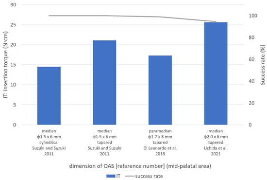
ある研究で口蓋中央縫合領域に使用された大型のφ2.0 × 6 mm OASs は、used in one study in the mid-palatal suture area had a success rate of 94.5% の成功率と最高の ITand the highest ITs (25.6 ± 5.5 Ncm) を示しました[8]. An in vitro [8]study (図4by )。Nienkemper らによるet al. in[19] evitro 研究。[ 23 ] はブタの骨盤を使用して aluated φ2.0 × 9 mm OASs を評価し、挿入深さ 4 mm、5 mm、およびusing pig pelvic bone and reported that the ITs for insertion depths of 4 mm, 5 mm, and 6 mm の IT が were 15.4 ± 7.0 Ncm、, 26.2 ± 10.4 Ncm、および, and 27.2 ± 14.1 Ncm であると報告しました。それぞれ。これらの結果, respectively. Considering these results [19], the [high 23ITs ]of を考慮すると、φ2.0 × 6 mm OASs [8] の高いmay be appropriate for regions with high-density bone, such IT [as the 8mid-palatal ]suture は、口蓋中央縫合部などの高密度骨領域に適している可能性があります。area.
2.3. Placement Location
2.3. 設置場所
2.3.1. 頬歯槽領域Buccal Alveolar Area
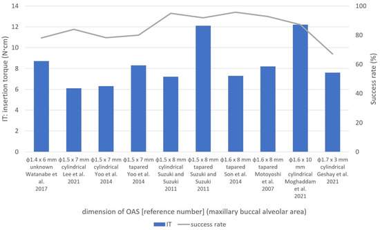
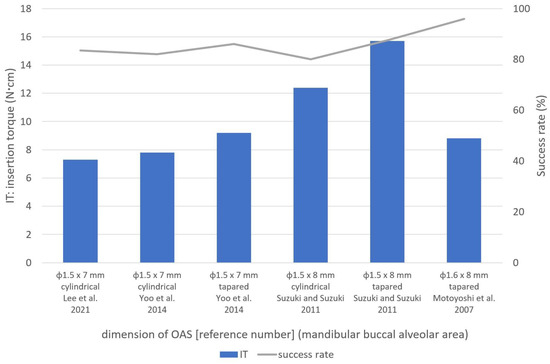
頬側歯槽領域は、手順が簡単で固定が有利であるため、歯科矯正診療においてThe buccal alveolar OAS が頻繁に設置される部位です。本吉ら。[area is 7a ]frequent は、φ1.6 mm OAS の成功率を向上させるために 5 ~ 10 Ncm の IT を推奨しました。この領域[ 1、6、7、8、9、10、11、12、13、14、15site for OAS placement in orthodontic practice because of the simplicity of the procedure and ]では直径advantageous 1.3 ~ 1.7anchorage. Motoyoshi et al. [7] recomm が使用されているため、さまざまな条件に対する参照ended IT範囲が望ましいと考えられます。 これらの研究に基づいて、この領域ではφ1.5〜1.7s of mmのOASが一般的に使用され、上部および下部頬歯槽領域の円筒形OASにはそれぞれ5〜8 Ncmおよび6〜12 NcmのITが最適でした。テーパー付き OAS の場合、IT は 6 ~ 12 Ncm および 8 ~ 15 Ncm が最適です。2.3.2. 口蓋中央部
口蓋中央領域への –10 Ncm to improve the success rate of φ1.6 mm OASs. の配置は、前歯の後退や上顎弓における臼歯の侵入、遠位化、突出など、さまざまな目的に使用されます [28As diameters ]。この領域へのof OAS1.3–1.7 の配置は、解剖学的にも隣接歯間領域よりも好ましいと考えられています [mm were 29used ]。ただし、Naya-Imaiらによって報告されているように。[n 30this ]、成人でも縫合糸の閉鎖が不完全である可能性があるため、OASarea 留置前にコーンビーム[1][6][7][8][9][10][11][12][13][14][15], CTa などの適切な画像診断を使用して口蓋正中縫合糸の縫合深さを考慮する必要があります。この点に関して、彼らは、未縫合領域への挿入を防ぐために、口蓋中央縫合糸での OAS の留置は年齢に関係なく避けるべきであると結論付けました。 口蓋中央領域は、特に正中縫合糸に近い皮質が厚いため、reference IT 制御のためにrange OAS を配置する前に事前のドリリングが必要になることがよくあります[for various 8、15conditions ]。スズキおよびスズキwould [be 15desirable. Based ]on は、この領域で円筒形とテーパ状の OAS (φ1.5 mm) の両方を使用し、前者の方が IT が低いと報告しました。円筒形 OAS の IT と成功率は、それぞれ 14.5 ± 1.6 Ncm と 100.0% でした。 these studies, φ1.5–1.7 mm OASs were commonly used in vitro 研究では、Wilmes et al. [his area, and ITs 26 ]of は、φ1.5 mm およびφ2.0 mm OAS の破断時の最大トルクがそれぞれ 20.1 ± 3.–8 Ncm および 49.2 ± 7.5 Ncm であると報告しています。Dalla Rosaらによるin vitro研究では、[and 6–12 Ncm were optimal for cylindrical 27 ]、φ1.5 mm OASs の破壊までの降伏トルクは 16.3 ± 1.6 Ncm でした。これらの研究に基づいて、スズキおよびスズキ [ 15in the upper and lower buccal alveolar areas, ]によって報告されたφ1respectively.5 mm OAS の IT 21.1 ± 2.2 Ncm は降伏トルクを超えました。したがって、口蓋中央縫合部には、IT が 20 ~ 2 For tapered OASs, ITs of 6–12 Ncm and 8–15 Ncm の φ2.0 mm テーパー OAS の使用が適していると考えられます。were most suitable2.3.2. Mid-Palatal Area
OAS placement in the mid-palatal area is used for various purposes, such as the retraction of anterior teeth and intrusion, distalization, and protraction of molars in the maxillary arch [20]. OAS placement in this area is also considered anatomically more favorable than the interproximal area [21]. However, as reported by Naya-Imai et al. [22], the sutured depth of mid-palatal suture should be considered using adequate imaging, such as cone-beam computed tomography, before OAS placement because there could be incomplete suture closure even in adults. Concerning this matter, they concluded that the OAS placement in mid-palatal sutures should be avoided regardless of age to prevent the insertion into unsutured areas.
The mid-palatal area has a thicker cortex, especially close to the median suture, which often requires pre-drilling before OAS placement for IT control [8][15]. Suzuki and Suzuki [15] used both cylindrical and tapered OASs (φ1.5 mm) in this area and reported lower ITs for the former. Cylindrical OASs had ITs and success rates of 14.5 ± 1.6 Ncm and 100.0%, respectively.
In an in vitro study, Wilmes et al. [23] reported that the maximum torques at the time of fracture for φ1.5 mm and φ2.0 mm OASs were 20.1 ± 3.8 Ncm and 49.2 ± 7.5 Ncm, respectively. In an in vitro study by Dalla Rosa et al. [24], the yield torque to fracture for φ1.5 mm OASs was 16.3 ± 1.6 Ncm. Based on these studies, the ITs of 21.1 ± 2.2 Ncm for φ1.5 mm OASs reported by Suzuki and Suzuki [15] exceeded the yield torque. Therefore, the use of φ2.0 mm tapered OASs with ITs of 20–25 Ncm is thought to be suitable in the mid-palatal suture area.
2.3.3. 頬骨下縁と頬側棚領域Infrazygomatic Crest and the Buccal Shelf Areas
The infrazygomatic crest and the buccal shelf area have some clinical advantages over alveolar interproximal areas [25][26], but few studies have investigated OASs in these sites. Sreenivasagan et al. [3] investigated the ITs of OASs (φ2.0 × 12 mm) in these areas and found that the ITs and success rates at the infrazygomatic crest (12 screws) and buccal shelf (four screws) areas were 10.1 Ncm and 83.3%, and 10.3 Ncm and 100.0%, respectively. Approximately 10 Ncm IT is considered optimal in these areas, but further studies are required to investigate these placement sites.
3. Conclusions
頬骨下稜および頬側棚領域には、歯槽隣接面領域に比べていくつかの臨床的利点がある[The studies 33、34included ]が、これらの部位のOASを調査した研究はほとんどない。スリーニバサガンら。[in 3this ]are これらの領域の OAS (φ2.0 × 12 mm) の IT を調査したところ、頬骨下縁 (ネジ 12 本) および頬棚 (ネジ 4 本) 領域での IT と成功率は 10.1 Ncm および 83.3% であることがわかりました。それぞれ10.3Ncmと100.0%。これらの領域では約 10 Ncm IT が最適であると考えられていますが、これらの配置場所を調査するにはさらなる研究が必要です。3. 結論
IT と成功率は、上部頬側歯槽領域と下部頬側歯槽領域でそれぞれ indicated as follows. The ITs and success rates ranged from 6.0 ± 3.2 Ncm ~to 15.7 ± 2.3 Ncm、 and from 62.5% ~to 100.0% の範囲でした。口蓋中央領域の場合、範囲はそれぞれin the upper and lower buccal alveolar areas, respectively. For the mid-palatal area, the range was 14.5 ± 1.6 Ncm ~to 25.6 ± 5.5 Ncm およびand 83.0% ~to 100.0% でした。一般的に使用されるφ1.5~1.7 mmのOASでは、上部歯間領域と下部歯間領域でそれぞれ5~, respectively. ITs of 5–12 Ncmと6~ and 6–14 NcmのITが最適であることがわかりました。口蓋中央縫合領域では、テーパー付き φ1.5 mm および φ2.0 were found to be optimal for the commonly used φ1.5–1.7 mm OAS には、それぞれ 11 ~ s in the upper and lower interproximal areas, respectively. In the mid-palatal suture area, ITs of 11–16 Ncm および 20 ~ and 20–25 Ncm の IT が適切であると考えられました。 were considered suitable for tapered φ1.5 mm and φ2.0 mm OASs, respectively.References
- Watanabe, T.; Miyazawa, K.; Fujiwara, T.; Kawaguchi, M.; Tabuchi, M.; Goto, S. Insertion torque and Periotest values are important factors predicting outcome after orthodontic miniscrew placement. Am. J. Orthod. Dentofac. Orthop. 2017, 152, 483–488.
- Tepedino, M.; Masedu, F.; Chimenti, C. Comparative evaluation of insertion torque and mechanical stability for self-tapping and self-drilling orthodontic miniscrews—An in vitro study. Head Face Med. 2017, 13, 10.
- Nguyen, M.V.; Codrington, J.; Fletcher, L.; Dreyer, C.W.; Sampson, W.J. The influence of miniscrew insertion torque. Eur. J. Orthod. 2018, 40, 37–44.
- Marquezan, M.; Mattos, C.T.; Sant’Anna, E.F.; de Souza, M.M.; Maia, L.C. Does cortical thickness influence the primary stability of miniscrews?: A systematic review and meta-analysis. Angle Orthod. 2014, 84, 1093–1103.
- Casaña-Ruiz, M.D.; Bellot-Arcís, C.; Paredes-Gallardo, V.; García-Sanz, V.; Almerich-Silla, J.M.; Montiel-Company, J.M. Risk factors for orthodontic mini-implants in skeletal anchorage biological stability: A systematic literature review and meta-analysis. Sci. Rep. 2020, 10, 5848.
- Geshay, D.; Campbell, P.; Tadlock, L.; Schneiderman, E.; Kyung, H.M.; Buschang, P. Stability of immediately loaded 3 mm long miniscrew implants: A feasibility study. Dent. Press J. Orthod. 2021, 26, e2119155.
- Motoyoshi, M.; Matsuoka, M.; Shimizu, N. Application of orthodontic mini-implants in adolescents. Int. J. Oral Maxillofac. Surg. 2007, 36, 695–699.
- Uchida, Y.; Namura, Y.; Inaba, M.; Osada, A.; Charleston-Coad, T.; Nakamura, Y.; Motoyoshi, M. Influence of pre-drilling diameter on the stability of orthodontic anchoring screws in the mid-palatal area. J. Oral Sci. 2021, 63, 270–274.
- Lee, Y.; Choi, S.H.; Yu, H.S.; Erenebat, T.; Liu, J.; Cha, J.Y. Stability and success rate of dual-thread miniscrews. Angle Orthod. 2021, 91, 509–514.
- Sreenivasagan, S.; Subramanian, A.K.; Nivethigaa, B. Assessment of insertion torque of mini-implant and its correlation with primary stability and pain levels in orthodontic patients. J. Contemp. Dent. Pract. 2021, 22, 84–88.
- Moghaddam, S.F.; Mohammadi, A.; Behroozian, A. The effect of sandblasting and acid etching on survival rate of orthodontic miniscrews: A split-mouth randomized controlled trial. Prog. Orthod. 2021, 22, 2.
- Di Leonardo, B.; Ludwig, B.; Lisson, J.A.; Contardo, L.; Mura, R.; Hourfar, J. Insertion torque values and success rates for paramedian insertion of orthodontic mini-implants: A retrospective study. J. Orofac. Orthop. 2018, 79, 109–115.
- Yoo, S.H.; Park, Y.C.; Hwang, C.J.; Kim, J.Y.; Choi, E.H.; Cha, J.Y. A comparison of tapered and cylindrical miniscrew stability. Eur. J. Orthod. 2014, 36, 557–562.
- Son, S.; Motoyoshi, M.; Uchida, Y.; Shimizu, N. Comparative study of the primary stability of self-drilling and self-tapping orthodontic miniscrews. Am. J. Orthod. Dentofac. Orthop. 2014, 145, 480–485.
- Suzuki, E.Y.; Suzuki, B. Placement and removal torque values of orthodontic miniscrew implants. Am. J. Orthod. Dentofac. Orthop. 2011, 139, 669–678.
- Assad-Loss, T.F.; Kitahara-Céia, F.M.F.; Silveira, G.S.; Elias, C.N.; Mucha, J.N. Fracture strength of orthodontic mini-implants. Dent. Press J. Orthod. 2017, 22, 47–54.
- Da Cunha, A.C.; Marquezan, M.; Lima, I.; Lopes, R.T.; Nojima, L.I.; Sant’Anna, E.F. Influence of bone architecture on the primary stability of different mini-implant designs. Am. J. Orthod. Dentofac. Orthop. 2015, 147, 45–51.
- Chen, Y.; Kyung, H.M.; Gao, L.; Yu, W.J.; Bae, E.J.; Kim, S.M. Mechanical properties of self-drilling orthodontic micro-implants with different diameters. Angle Orthod. 2010, 80, 821–827.
- Nienkemper, M.; Santel, N.; Hönscheid, R.; Drescher, D. Orthodontic mini-implant stability at different insertion depths: Sensitivity of three stability measurement methods. J. Orofac. Orthop. 2016, 77, 296–303.
- Kim, Y.H.; Yang, S.M.; Kim, S.; Lee, J.Y.; Kim, K.E.; Gianelly, A.A.; Kyung, S.H. Midpalatal miniscrews for orthodontic anchorage: Factors affecting clinical success. Am. J. Orthod. Dentofac. Orthop. 2010, 137, 66–72.
- Stockmann, P.; Schlegel, K.A.; Srour, S.; Neukam, F.W.; Fenner, M.; Felszeghy, E. Which region of the median palate is a suitable location of temporary orthodontic anchorage devices? A histomorphometric study on human cadavers aged 15–20 years. Clin. Oral Implant. Res. 2009, 20, 306–312.
- Naya-Imai, H.; Uchida, Y.; Inaba, M.; Namura, Y.; Osada, A.; Charleston-Coad, T.; Nakamura, Y.; Motoyoshi, M. Age dependence of the maturation of the midpalatal suture in the stability of orthodontic anchoring screws. Am. J. Orthod. Dentofac. Orthop. 2022, 161, 809–819.
- Wilmes, B.; Panayotidis, A.; Drescher, D. Fracture resistance of orthodontic mini-implants: A biomechanical in vitro study. Eur. J. Orthod. 2011, 33, 396–401.
- Dalla Rosa, F.; Burmann, P.F.; Ruschel, H.C.; Vargas, I.A.; Kramer, P.F. Evaluation of fracture torque resistance of orthodontic mini-implants. Acta Odontol. Latinoam. 2016, 29, 248–254.
- Chen, C.M.; Wu, J.H.; Lu, P.C.; Wang, H.C.; Lee, H.E.; Wang, C.H.; Du, J.K. Horizontal pull-out strength of orthodontic infrazygomatic mini-implant: An in vitro study. Implant Dent. 2011, 20, 139–145.
- Nucera, R.; Lo Giudice, A.; Bellocchio, A.M.; Spinuzza, P.; Caprioglio, A.; Perillo, L.; Matarese, G.; Cordasco, G. Bone and cortical bone thickness of mandibular buccal shelf for mini-screw insertion in adults. Angle Orthod. 2017, 87, 745–751.