Bulk metallic glasses (BMGs) display excellent strength, high hardness, exceptional wear resistance and corrosion resistance owing to its amorphous structure. However, the manufacturing of large-sized and complex shaped BMG parts faces significant difficulties, which seriously hinders their applications. Laser powder bed fusion (LPBF) is a typical additive manufacturing (AM) technique with a cooling rate of up to 108 K/s, which not only allows for the formation of amorphous structures but also solves the forming problem of complex-shaped BMG parts. In recent years, a large amount of work has been carried out on the LPBF processing of BMGs.
- additive manufacturing
- laser powder bed fusion
- bulk metallic glasses
1. Introduction
2. BMGs Fabricated using LPBF
BMGs are a family of multicomponent alloys, and a range of alloying systems like Zr-, Ti-, Fe-, Cu-, Mg-, and La-based alloys have been developed through conventional processing. However, only a few BMG alloys, mainly in Zr-, Fe-, Al-, Cu-, and Ti-based glass systems, have been prepared using LPBF due to the difficulty in obtaining the required BMG powders for printing. Table 1 summarizes the BMGs that have been fabricated using LPBF in recent years and their structural state.| Composition (at%) | Amorphization Degree (XRD) | Crystallinity (DSC) | Crystalline Phase | Ref. |
|---|---|---|---|---|
| Zr52.5Cu17.9Ni14.6Al10Ti5 | Amorphous | - | - | [30] |
| Zr52.5Cu17.9Ni14.6Al10Ti5 | Amorphous | 4.1% | - | [31] |
| Zr55Cu30Al10Ni5 | Partially crystalline | 16.9% | Al5Ni3Zr2 | [32][33] |
| Zr57.4Ni8.2Cu16.4Ta8Al10 | Partially crystalline | 8% | Ta | [34] |
| Zr59.3Cu28.8Nb1.5Al10.4 | Amorphous | 4.0% |
4.4. Crystallization
Another challenge in the preparation of BMG using LPBF is the generation of crystallization defects due to the variation of thermal history during the printing process. The presence of crystalline phases can be directly detected by XRD when the degree of crystallinity exceeds 10%. As mentioned earlier, in most cases, the crystallization of BMG is harmful and undesirable [46][54][55]. The mechanical properties of bulk metallic glass, especially the fracture stress, are very sensitive to its structural state.4.5. HAZ
Owing to the uncontrolled crystallization that occurs in the heat-affected zone (HAZ), obtaining a monolithic glass remains a challenge for most BMG systems. In most cases, crystallization leads to an increased risk of cracking in LPBF-fabricated BMGs and adversely affects the densification and performance of the fabricated parts. Therefore, understanding the microstructure and formation mechanism of the HAZ is essential to enhance the mechanical properties of LPBF-printed BMGs. Current studies generally agree that the microstructure of LPBF-fabricated BMG samples consists of two main regions, the solidified molten pool and the HAZ [32][33][48][94]. Typically, the SMP consists of an amorphous phase, while the HAZ is partially crystalline (i.e., amorphous and crystalline phases coexist). In this case, the boundary between the fully amorphous and partially crystallized regions can be regarded as the edge of the HAZ. Li et al. [50] performed a single line scan of an Al86Ni6Y4.5Co2La1.5 BMG. It was found that the further away from the center of the solidified molten pool, the more severe the crystallization was. The width of the HAZ increased with increasing laser power and the crystallization became more severe. Although the cooling rate at a high laser power is fast, the crystallization of BMG increases. This indicates that the formation of the amorphous phase is not only affected by the cooling rate, but is also more easily affected by the HAZ in the process of forming the Al-based BMG using LPBF. Therefore, it is more important to consider the HAZ factor for the optimization of the process parameters during the LPBF of BMGs.5. Measures for Improving Mechanical Properties of LPBF-Fabricated BMGs
5.1. Optimization of LPBF Process Parameters
By optimizing LPBF process parameters, the formation of defects in the as-built BMG can be effectively suppressed. Therefore, the optimization of LPBF process parameters is an important factor in preparing BMG parts with excellent mechanical properties [43][46]. Table 2 summarizes the optimal process parameters reported in the literature that can achieve an amorphous structure in the as-built BMG parts.| Alloy | Laser Power (W) |
Scan Speed (mm/s) |
Hatch Spacing (mm) |
Thickness (mm) |
Energy Density (J/mm3) |
Ref. | |||||
|---|---|---|---|---|---|---|---|---|---|---|---|
| Zr52.5Cu17.9Ni14.6Al10Ti5 | 400 | 2000 | 0.15 | 0.1 | 13.3 | [30] | |||||
| Zr52.5Cu17.9Ni14.6Al10Ti5 | 105 | 1000 | 0.2 | 0.04 | 13.1 | [31] | |||||
| Zr52.5Cu17.9Ni14.6Al10Ti5 | 109.5 | 1000 | 0.2 | 0.04 | 13.7 | [79] | |||||
| Zr52.5Cu17.9Ni14.6Al10Ti5 | 109.5 | 1000 | 0.2 | 0.04 | 13.7 | [95] | |||||
| - | |||||||||||
| Zr55Cu30Al10Ni5 | [ | 35 | ] | [36] | |||||||
| 240 | 1200 | 0.1 | 0.06 | 33.3 | [ | 32] | Zr60.14Cu22.31Fe | ||||
| Zr55Cu304.85Al9.7Ag3 | Amorphous | 5.3% | Al10Ni5 | 240- | [37][38] | ||||||
| 1200 | 0.1 | 0.06 | 33.3 | [ | 96 | ] | Zr60Fe10Cu20Al10 | Amorphous | 3.1% | - | [39] |
| Zr57.4Ni8.2Cu16.4Ta8Al10 | 100~300 | 1200~2000 | 0.1 | 0.06 | 22.9 | [34] | Fe54.35Cr18.47Mn2.05Mo13.93W5.77B3.22C0.90Si1.32 | Amorphous | - | ||
| Zr | - | 59.3Cu28.8Nb1.5Al10.4 (AMZ4) | [ | 40] | |||||||
| 30 | 600 | 0.09 | 0.02 | 27.8 | [ | 74] | Fe37.5Cr27.5Mo10C12B13 | Amorphous | - | - | |
| Zr60.14Cu22.31Fe4.85Al9.7Ag3 | [ | 200 | 41 | ][42] | |||||||
| 1600 | 0.1 | 0.06 | 20.8 | [ | 37 | ] | Fe68.3C6.9Si | ||||
| Zr60.14Cu22.312.5B6.7P8.7Cr2.3Mo2.5AlFe4.85Al9.7Ag32.1 | Amorphous | 2% | 160- | [43] | |||||||
| 1200 | 0.1 | 0.06 | 22.2 | [ | 97 | ] | Fe55Cr25Mo16B2C2 | ||||
| Fe68.3C6.9Si2.5B | Amorphous | 0.8% | - | 6.7P8.7Cr2.3Mo2.5Al2.1[44] | |||||||
| 340 | 1500 | 0.11 | 0.075 | 27.5 | [ | 43] | Fe71Si10B11C6Cr2 | Partially crystalline | |||
| Fe | 10.4% | 55Cr25Mo16B2C2 | Fe2B, Fe3B, α-Fe(Si), Fe3Si | [45] | |||||||
| 100 | 300 | 0.105 | 0.03 | 105.8 | [ | 44] | Fe74Mo4P10C7.5B2.5Si | ||||
| Fe74Mo4P10C7.52 | B2.5Partially crystalline | Si2- | 320α-Fe, γ-Fe, Fe23 | 3470B6 | [46] | ||||||
| 0.124 | 0.05 | 14.9 | [ | 46 | ] | Fe70Cr5Ni3Mo3W9Si5B5 | |||||
| Ti47Cu | Partially crystalline | 38Zr20% | 7.5Fe2.5Sn2Si1Ag2α-Fe, Fe2B | [ | 60 | 200047] | |||||
| 0.14 | 0.04 | 5.4 | [ | 49 | ] | Fe43.7Co7.3Cr14.7Mo12.6C15.5B4.3Y1.9 | Partially crystalline | ||||
| Mg | 36.1% | 65Cu20Zn5Y10 | (Fe,Cr) | 10023(C,B)6, (Fe,Cr)23B | [48] | ||||||
| Ti47Cu38Zr7.5Fe2.5Sn2Si1Ag2 | Amorphous | - | - | [49] | |||||||
| Al86Ni6Y4.5Co2La1.5 | Partially crystalline | - | - | [50] | |||||||
| Al85Ni5Y6Co2Fe2 | Fully crystallized | - | - | [51] | |||||||
| Al85Nd8Ni5Co2 | Partially crystalline | - | α-Al, AlNdNi4, Al4CoNi2, AlNd3 | [52] | |||||||
| Cu46Zr47Al6Co1 | Partially crystalline | - | B2-CuZr | [53] | |||||||
| Cu50Zr43Al7 | Partially crystalline | 18.9% | CuZr, Cu10Zr7, Al2Zr | [54] | |||||||
| Cu46Zr46Al8 | Partially crystalline | 12% | B2-ZrCu, cube phase | [55] | |||||||
| Cu50Zr50 | Partially crystalline | 37.1% | B2-ZrCu, B19′-ZrCu, Cu5Zr | [56] | |||||||
| Pd43Cu27Ni10P20 | Amorphous | - | - | [57] |
2.1. Zr-Based BMG
Zr-based BMGs have an excellent glass forming ability (GFA), and using copper mold casting can easily obtain BMG rods with a diameter larger than 10 mm [58]. This characteristic also enables Zr-based alloys to exhibit excellent LPBF formability. In 2016, a Zr-based BMG with a composition of Zr52.5Ti5Cu17.9Ni14.6Al10 was successfully manufactured through LPBF. Since then, the LPBF of Zr-based BMGs has attracted a lot of attention [31][32][33][34][35][36][37][38][39][41]. The most common alloy among them was Zr59.3Cu28.8Al10.4Nb1.5, also known as AMZ4. However, since AMZ4 is a commercial alloy powder, it usually includes more impurities. Therefore, AMZ4 BMG requires more work to form an amorphous phase than other Zr-based amorphous alloys [35][36].2.2. Fe-Based BMG
The GFA of the first Fe-based MGs was relatively bad, and their critical sizes were too small, making them difficult to form and process. Previous studies have found that the addition of C and B elements to Fe-based alloys can enhance their GFA, and the large Fe-based BMG components have been successfully fabricated [59]. In addition to their unique mechanical properties, Fe-based BMGs have exceptional magnetic properties. These properties are attributed to the absence of crystal-related defects in BMGs. The Fe-based BMG’s soft magnetic characteristics are diminished by crystallization, therefore requires a high amorphous structural state [60]. It is obvious that the traditional copper mold casting technology is difficult to prepare large-sized Fe-based BMGs with fully amorphous structures, and LPBF additive manufacturing technology provides an opportunity to overcome this limitation. In 2013, an Fe-based BMG (Fe74Mo4P10C7.5B2.5Si2) was prepared using LPBF [46].2.3. Al-Based BMG
Al-based BMGs have an excellent strength-to-weight ratio and corrosion resistance. However, the GFA of Al-based alloys is very bad, which makes it difficult to prepare Al-based MGs in a completely amorphous state and with dimensions larger than 1 mm by conventional methods over a long period of time [61][62].2.4. Cu-Based BMG
Cu-based BMG is known for its low cost and high strength [63]. The Cu–Zr–Al system has the highest as-cast strength among the Cu-based BMGs, and its fracture strength is generally in the range of 1.6 GPa to 2.0 GPa. However, their GFA is low, with a critical casting diameter of only 3 mm. Their GFA can be further increased by adding more elemental components. In 2019, a ternary Cu-based BMG, Cu50Zr43Al7, was prepared for the first time using LPBF technology [54]. Some large and complex amorphous parts were obtained using the optimal process parameters of LPBF (E = 25 J/mm3).2.5. Ti-Based BMG
Ti-based alloys are employed in a wide range of applications such as aerospace, orthopedics and dental implants, owing to their great biocompatibility and strength-to-weight ratio. However, the research on Ti-based BMGs has not been deep enough, and few Ti-based BMG systems have been successfully developed. Although the addition of the element beryllium can significantly increase the GFA of Ti-based alloys, leading to a critical casting diameter of more than 14 mm. Unfortunately, beryllium is a toxic element, so its application is limited to a certain extent. In 2015, a Ti-based BMG (Ti47Cu38Zr7.5Fe2.5Sn2Si1Ag2), free of beryllium and nickel elements, was successfully developed with a critical casting diameter of 7 mm [64].2.6. Precious BMG
Precious metals have numerous applications due to their metallic luster and superior mechanical characteristics like hardness and wear resistance, especially in commercial areas such as the watch and jewelry industry [65][66]. Usually, the mechanical performances of precious BMGs are higher than the performances of their crystalline alloy counterparts. Therefore, it makes sense to design and develop precious BMGs to meet the needs of the watch and jewelry industry [67][68]. So far, BMGs based on various precious metals have been developed, like Pd-based [69], Pt-based [70], and Ag-based BMGs [71].3. Mechanical Properties of LPBF-Fabricated BMGs
3.1. Microhardness
It is well-known that hardness is an important mechanical property of a material, and therefore the hardness of a material is required to be tested [72]. Hardness testing is most commonly used for BMGs manufactured by the LPBF process. Shi et al. [73] tested the hardness of AMZ4 and found the BMG made using LPBF with porosity as low as 0.45% had a macroscopic hardness of 484 HV5, which reaches the hardness of the corresponding cast BMG. Sohrabi et al. [74] conducted microhardness tests on AMZ4 BMG made using LPBF, and even though the BMG contained nanocrystals, a high hardness of 446 HV5 was achieved. Currently, the difference in the microhardness between BMG made using LPBF and traditional cast BMG can be almost ignored [37][75][76].3.2. Nanohardness
The detection of heterogeneity in the structure of BMGs fabricated via LPBF is usually revealed through the use of nanohardness maps [30][74][77][78][79]. For example, Li et al. [30] revealed the heterogeneity of LPBF-fabricated Zr52.5Ti5Cu17.9Ni14.6Al10 BMG samples using nanohardness mapping with a maximum average hardness of about 6.5 GPa. Sohrabi et al. [74] conducted the nanoindentation testing of AMZ4 manufactured through LPBF, and the average value was 5.13 ± 0.25 GPa. The hardness is relatively uniform overall, and the red spots are due to nanocrystal precipitation. Compared with BMG manufactured using traditional technology, the amorphous phase hardness of BMG manufactured with LPBF is relatively higher [80]. Fe55Cr25Mo16B2C2 BMG prepared using LPBF, has a nanohardness of 14 GPa, equivalent to 1260 HV [44]. During the nanoindentation test of LPBF-fabricated {(Fe0.6Co0.4)0.75B0. 2Si0.05}96Nb4 BMG, Luo et al. [78] found that the amorphous content decreased with the increase of the LPBF laser energy input, and the hardness increased, with a maximum nanohardness of 16.9 ± 1.1 GPa [78].3.3. Micropillar Compression Behavior
Size effects have been observed in BMGs manufactured using LPBF technology [81]. The properties of the amorphous structure of the BMG itself can be tested during compression tests on BMG microcolumns prepared using LPBF by ignoring the defects introduced and crystallization initiated during the layer-by-layer additive manufacturing process [44][76][82]. Therefore, the compressive strength of a micropillar specimen of Fe55Cr25Mo16B2C2 prepared using LPBF can reach 6000 MPa, which is more consistent with the BMG material’s theoretical strength [44].3.4. Compressive Behavior
The most studied mechanical property in BMG manufactured through LPBF is compressive strength. The fracture strength of various 3D-printed BMGs ranges from 100–1800 MPa, while the compressive plastic strain ranges from only 0–3.17%. The strength of Zr- and Ti-based BMGs formed by 3D printing is above 1500 MPa, but their maximum compressive plasticity is only 2.15% [34]. In terms of plasticity, the majority of LPBF-fabricated BMGs that have been documented thus far exhibit negligible or no compression plasticity at ambient temperature, as is the case with other methods of producing BMGs. The 3D-printed Zr60.14Cu22.31Fe4.85Al9.7Ag3 BMG also exhibits a strong dimensional impact, similarly to the casting condition [83]. When the LPBF-fabricated sample’s size was shrunk from 3 mm to 1 mm, the plastic strain increased by about three times [37]. This may be due to the fact that the smaller the size of the sample, the fewer defects are formed by the LPBF.3.5. Tensile Behavior
There has been very little research into the tensile properties of LPBF-prepared BMGs, with only three studies reported so far, and all of them were carried out on the industrial-grade alloy Zr59.3Cu28.8Al10.4Nb1.5 (AMZ4) BMG [84][85][86]. Best et al. [86] conducted tensile tests on LPBF-fabricated AMZ4 BMG, and the samples underwent a typical brittle fracture with a fracture strength of only 1.08 GPa, which is considerably lower than the compressive strength of the material of 1.8 GPa [76]. The loss in the tensile strength may be attributed to the presence of defects in the samples. Shi et al. [84] used LPBF to create three different sets of uniaxial tensile samples with varying porosity levels, all of which fractured catastrophically under tension, with negligible macroscopic plasticity observed. The highest fracture strength measured was 1326 MPa.4. Effect of Defects on Mechanical Properties of LPBF-Fabricated BMGs
Unlike conventional copper mold casting, the LPBF process is based on layer-by-layer fabrication, which usually produces more defects during the manufacturing process, thus seriously affecting the mechanical performances of structural components [87]. Therefore, it is crucial to deeply understand the formation mechanism of defects in amorphous alloys during laser 3D printing, which is a prerequisite for developing printing strategies to reduce or eliminate 3D printing defects. These defects are divided into the following categories: porosity, LoF, microcracks, crystallization, and HAZ.
4.1. Porosity
The most common issues are porosity defects, which significantly affect the mechanical performance of BMG parts produced with LPBF technology. Porosity resulting from the evaporation of volatile or low melting point materials in the molten pool, and porosity created by unstable molten pool collapse in the keyhole molten pool mode are the two primary causes of porosity during the LPBF production of BMG [88][89]. For example, Qiu et al. [87] found that the appropriate scanning speed and laser power are favorable to reduce the porosity; an increase in the scanning speed leads to an increase in porosity, which is due to the instability of the flow of the molten pool and the splashing of the molten material at a high scanning speed. Due to the limited GFA of the BMG, the temperature cooling rate is more demanding, requiring faster scanning speeds as well as smaller energy inputs. As a result, the lack of energy input can be prone to a porous BMG and the incomplete melting of the powder. Porosity has been found in many LPBF studies on the preparation of metallic glasses [40][43][46][48][57][78][84]. Nong et al. [40] and Jung et al. [43] found that LPBF-fabricated Fe-based BMG samples prepared with a low energy density had a highly porous microstructure. Therefore, for the preparation of BMG through LPBF, the presence of pores is one of the main formation problems faced when preparing large-sized samples. Porosity is a factor that can lead to the premature failure of BMG parts manufactured using LPBF.4.2. LoF
Lack of fusion (LoF) defects are caused by insufficient molten metal to completely fill gaps during the LPBF process. Generally, it is believed that if the laser energy input is too low, it will result in a reduction of the molten pool width, allowing insufficient overlap between single-track melting pools, leaving unmelted powder. During the melting of the next powder layer, the low laser energy input fails to penetrate the powder layer, making it difficult to remelt the remaining unmelted powder in the upper layer, resulting in the formation of irregular keyholes, i.e., LoF defects [90]. Due to the fact that the shape of LoF is mostly irregular and its size can reach hundreds of micrometers, it may lead to stress concentration and damage mechanical properties [57]. Currently, several studies on the LPBF of BMG attribute LoFs to premature failure in tensile [85][86] and compressive [31] tests. Pauly et al. [31] reconstructed LPBF-prepared compression test specimens by μ-CT and found that the presence of large holes in the center of the specimens, i.e., LoF defects.4.3. Microcracks
Microcracks are another common defect in 3D-printed BMG. During the LPBF process, only a small portion of the material undergoes rapid heating/cooling cycles, which may lead to sharp temperature gradients, significant thermal fluctuations, severe shrinkage, and high thermal stress, making BMGs very prone to cracking [48]. The presence of cracks considerably deteriorates the mechanical behavior of LPBF-fabricated BMGs. The BMGs formed using LPBF reported between 2013 and 2023 exhibit varying degrees of cracking, with the brittle Fe- and Al-based BMG systems being more prone to the occurrence of cracks [32][40][41][42][43][45][46][48][50][91][92][93]. Paul et al. [46] found the occurrence of cracks in Fe-based BMG samples fabricated using LPBF due to the high cooling rate of LPBF and the limited ductility of Fe-based BMG. Subsequently, Jung et al. [43] investigated the effect of LPBF process parameters on the microstructure of an Fe68.3C6.9Si2.5B6.7P8.7Cr2.3Mo| 1000 | ||||||
| 0.06 | ||||||
| 0.05 | ||||||
| 33.3 | ||||||
| [ | ||||||
| 98 | ||||||
| ] | ||||||
| Al | ||||||
| 86 | ||||||
| Ni6Y4.5Co2La1.5 | 120 | 1000 | - | - | - | [50] |
| Al85Ni5Y6Co2Fe2 | 200 (80) | 625 | 0.15 | 0.05 | 42.7 (17.1) | [51] |
| Al85Nd8Ni5Co2 | 320 | 1455 | 0.11 | 0.05 | 40.0 | [52] |
| Cu50Zr43Al7 | 150 | 2000 | 0.1 | 0.03 | 25 | [54] |
| Cu46Zr46Al8 | 99 | 1000 | 0.18 | 0.04 | 14.3 | [55] |
| Pd47Cu23Ni10P20 | 60 | 600 | 0.15 | 0.04 | 4.7 | [57] |
5.2. Modifying the Scanning Strategy
The quality of BMG formed parts depends not only on the process parameters but also on the scanning strategy. In addition to conventional linear scanning, studies have reported multiple scanning [30], two-step (point-random) scanning strategy (Figure 19a) [45] and layer-by-layer rotational 90° laser scanning modes [40].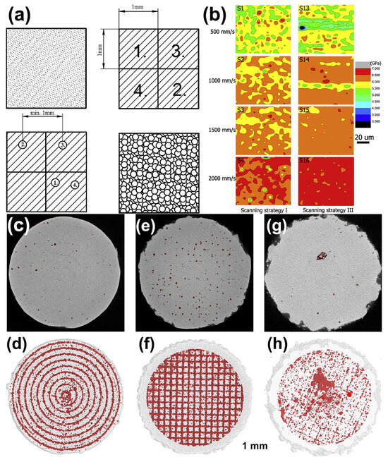
6. Conclusions
Numerous studies have revealed that the presence of defects in LPBF-fabricated BMGs, including the porosity, LoF, microcracks, crystallization, and HAZ, plays a decisive role in weakening their mechanical properties. The efforts to improve the quality and mechanical performance of LPBF-printed BMGs, such as parameter optimization and scanning strategy modification have been summarized and commented. The strength of LPBF additively manufactured BMGs is significantly lower than that of their cast counterparts due to the existence of defects in the as-built BMG parts. However, their strength can be further enhanced by controlling defects in the as-printed BMGs (reducing or even eliminating defects). It can be foreseen that LPBF is expected to develop into mainstream manufacturing technology for large-sized and complex-shaped BMG components.
References
- Cohen, M.H.; Turnbull, D. Metastability of Amorphous Structures. Nature 1964, 203, 964.
- Wang, W.H.; Dong, C.; Shek, C.H. Bulk Metallic Glasses. Mater. Sci. Eng. R Rep. 2004, 44, 45–89.
- Dun, C.; Liu, H.; Hou, L.; Xue, L.; Dou, L.; Yang, W.; Zhao, Y.; Shen, B. Ductile Co–Nb–B bulk metallic glass with ultrahigh strength. J. Non-Cryst. Solids 2014, 386, 121–123.
- Jiang, Q.K.; Liu, P.; Ma, Y.; Cao, Q.P.; Wang, X.D.; Zhang, D.X.; Han, X.D.; Zhang, Z.; Jiang, J.Z. Super elastic strain limit in metallic glass films. Sci. Rep. 2012, 2, 852.
- Khan, M.M.; Nemati, A.; Rahman, Z.U.; Shah, U.H.; Asgar, H.; Haider, W. Recent Advancements in Bulk Metallic Glasses and Their Applications: A Review. Crit. Rev. Solid State Mater. Sci. 2018, 43, 233–268.
- Pang, S.J.; Zhang, T.; Asami, K.; Inoue, A. Synthesis of Fe–Cr–Mo–C–B–P bulk metallic glasses with high corrosion resistance. Acta Mater. 2002, 50, 489–497.
- Yang, W.; Huo, J.; Liu, H.; Li, J.; Song, L.; Li, Q.; Xue, L.; Shen, B.; Inoue, A. Extraordinary magnetocaloric effect of Fe-based bulk glassy rods by combining fluxing treatment and J-quenching technique. J. Alloys Compd. 2016, 684, 29–33.
- Li, H.X.; Lu, Z.C.; Wang, S.L.; Wu, Y.; Lu, Z.P. Fe-based bulk metallic glasses: Glass formation, fabrication, properties and applications. Prog. Mater. Sci. 2019, 103, 235–318.
- Yang, W.; Wang, Q.; Li, W.; Xue, L.; Liu, H.; Zhou, J.; Mo, J.; Shen, B. A novel thermal-tuning Fe-based amorphous alloy for automatically recycled methylene blue degradation. Mater. Des. 2019, 161, 136–146.
- Jia, Z.; Duan, X.; Qin, P.; Zhang, W.; Wang, W.; Yang, C.; Sun, H.; Wang, S.; Zhang, L. Disordered Atomic Packing Structure of Metallic Glass: Toward Ultrafast Hydroxyl Radicals Production Rate and Strong Electron Transfer Ability in Catalytic Performance. Adv. Funct. Mater. 2017, 27, 1702258.
- Inoue, A.; Takeuchi, A. Recent development and application products of bulk glassy alloys. Acta Mater. 2011, 59, 2243–2267.
- Lashgari, H.R.; Chu, D.; Xie, S.; Sun, H.; Ferry, M.; Li, S. Composition dependence of the microstructure and soft magnetic properties of Fe-based amorphous/nanocrystalline alloys: A review study. J. Non-Cryst. Solids 2014, 391, 61–82.
- Inoue, A.; Nishiyama, N. New Bulk Metallic Glasses for Applications as Magnetic-Sensing, Chemical, and Structural Materials. MRS Bull. 2007, 32, 651–658.
- Yang, W.M.; Liu, H.S.; Liu, X.J.; Chen, G.X.; Dun, C.C.; Zhao, Y.C.; Man, Q.K.; Chang, C.T.; Shen, B.L.; Inoue, A.; et al. Correlation of atomic packing with the boson peak in amorphous alloys. J. Appl. Phys. 2014, 116, 123512.
- Wu, Y.; Wang, H.; Cheng, Y.; Liu, X.; Hui, X.; Nieh, T.; Wang, Y.; Lu, Z. Inherent structure length in metallic glasses: Simplicity behind complexity. Sci. Rep. 2015, 5, 12137.
- Hufnagel, T.C.; Schuh, C.A.; Falk, M.L. Deformation of metallic glasses: Recent developments in theory, simulations, and experiments. Acta Mater. 2016, 109, 375–393.
- Klement, W.; Willens, R.H.; Duwez, P. Non-Crystalline Structure in Solidified Gold–Silicon Alloys. Nature 1960, 187, 869–870.
- Schwarz, R.B.; Koch, C.C. Formation of amorphous alloys by the mechanical alloying of crystalline powders of pure metals and powders of intermetallics. Appl. Phys. Lett. 1986, 49, 146–148.
- Inoue, A.; Zhang, T.; Masumoto, T. Zr–Al–Ni Amorphous Alloys with High Glass Transition Temperature and Significant Supercooled Liquid Region. Mater. Trans. JIM 1990, 31, 177–183.
- Donovan, P.E. A yield criterion for Pd40Ni40P20 metallic glass. Acta Metall. 1989, 37, 445–456.
- Legg, B.A.; Schroers, J.; Busch, R. Thermodynamics, kinetics, and crystallization of Pt57.3Cu14.6Ni5.3P22.8 bulk metallic glass. Acta Mater. 2007, 55, 1109–1116.
- Yang, W.; Liu, H.; Zhao, Y.; Inoue, A.; Jiang, K.; Huo, J.; Ling, H.; Li, Q.; Shen, B. Mechanical properties and structural features of novel Fe-based bulk metallic glasses with unprecedented plasticity. Sci. Rep. 2014, 4, 6233.
- Liu, Y.H.; Wang, G.; Wang, R.J.; Zhao, D.Q.; Pan, M.X.; Wang, W.H. Super Plastic Bulk Metallic Glasses at Room Temperature. Science 2007, 315, 1385–1388.
- Kim, Y.C.; Kim, W.T.; Kim, D.H. A development of Ti-based bulk metallic glass. Mater. Sci. Eng. A 2004, 375–377, 127–135.
- Choi-Yim, H.; Xu, D.; Johnson, W.L. Ni-based bulk metallic glass formation in the Ni–Nb–Sn and Ni–Nb–Sn–X (X=B,Fe,Cu) alloy systems. Appl. Phys. Lett. 2003, 82, 1030–1032.
- Inoue, A.; Zhang, W.; Zhang, T.; Kurosaka, K. High-strength Cu-based bulk glassy alloys in Cu–Zr–Ti and Cu–Hf–Ti ternary systems. Acta Mater. 2001, 49, 2645–2652.
- Ma, H.; Xu, J.; Ma, E. Mg-based bulk metallic glass composites with plasticity and high strength. Appl. Phys. Lett. 2003, 83, 2793–2795.
- Hofmann, D.C.; Suh, J.-Y.; Wiest, A.; Duan, G.; Lind, M.-L.; Demetriou, M.D.; Johnson, W.L. Designing metallic glass matrix composites with high toughness and tensile ductility. Nature 2008, 451, 1085–1089.
- Johnson, W.L.; Kaltenboeck, G.; Demetriou, M.D.; Schramm, J.P.; Liu, X.; Samwer, K.; Kim, C.P.; Hofmann, D.C. Beating crystallization in glass-forming metals by millisecond heating and processing. Science 2011, 332, 828–833.
- Li, X.P.; Roberts, M.P.; O’Keeffe, S.; Sercombe, T.B. Selective laser melting of Zr-based bulk metallic glasses: Processing, microstructure and mechanical properties. Mater. Des. 2016, 112, 217–226.
- Pauly, S.; Schricker, C.; Scudino, S.; Deng, L.; Kühn, U. Processing a glass-forming Zr-based alloy by selective laser melting. Mater. Des. 2017, 135, 133–141.
- Ouyang, D.; Li, N.; Xing, W.; Zhang, J.; Liu, L. 3D printing of crack-free high strength Zr-based bulk metallic glass composite by selective laser melting. Intermetallics 2017, 90, 128–134.
- Yang, C.; Zhang, C.; Xing, W.; Liu, L. 3D printing of Zr-based bulk metallic glasses with complex geometries and enhanced catalytic properties. Intermetallics 2018, 94, 22–28.
- Zhang, P.; Ouyang, D.; Liu, L. Enhanced mechanical properties of 3D printed Zr-based BMG composite reinforced with Ta precipitates. J. Alloys Compd. 2019, 803, 476–483.
- Pacheco, V.; Karlsson, D.; Marattukalam, J.J.; Stolpe, M.; Hjörvarsson, B.; Jansson, U.; Sahlberg, M. Thermal stability and crystallization of a Zr-based metallic glass produced by suction casting and selective laser melting. J. Alloys Compd. 2020, 825, 153995.
- Marattukalam, J.J.; Pacheco, V.; Karlsson, D.; Riekehr, L.; Lindwall, J.; Forsberg, F.; Jansson, U.; Sahlberg, M.; Hjorvarsson, B. Development of process parameters for selective laser melting of a Zr-based bulk metallic glass. Addit. Manuf. 2020, 33, 101124.
- Zhang, C.; Li, X.; Liu, S.Q.; Liu, H.; Yu, L.J.; Liu, L. 3D printing of Zr-based bulk metallic glasses and components for potential biomedical applications. J. Alloys Compd. 2019, 790, 963–973.
- Xing, W.; Ouyang, D.; Chen, Z.; Liu, L. Effect of energy density on defect evolution in 3D printed Zr-based metallic glasses by selective laser melting. Sci. China Phys. Mech. Astron. 2020, 63, 226111.
- Luo, Y.; Xing, L.; Jiang, Y.; Li, R.; Lu, C.; Zeng, R.; Luo, J.; Zhang, P.; Liu, W. Additive manufactured large Zr-based bulk metallic glass composites with desired deformation ability and corrosion resistance. Materials 2020, 13, 597.
- Nong, X.D.; Zhou, X.L.; Ren, Y.X. Fabrication and characterization of Fe-based metallic glasses by Selective Laser Melting. Opt. Laser Technol. 2019, 109, 20–26.
- Mahbooba, Z.; Thorsson, L.; Unosson, M.; Skoglund, P.; West, H.; Horn, T.; Rock, C.; Vogli, E.; Harrysson, O. Additive manufacturing of an iron-based bulk metallic glass larger than the critical casting thickness. Appl. Mater. Today 2018, 11, 264–269.
- Hofmann, D.C.; Bordeenithikasem, P.; Pate, A.; Roberts, S.N.; Vogli, E. Developing processing parameters and characterizing microstructure and properties of an additively manufactured FeCrMoBC metallic glass forming alloy. Adv. Eng. Mater. 2018, 20, 1800433.
- Jung, H.Y.; Choi, S.J.; Prashanth, K.G.; Stoica, M.; Scudino, S.; Yi, S.; Kühn, U.; Kim, D.H.; Kim, K.B.; Eckert, J. Fabrication of Fe-based bulk metallic glass by selective laser melting: A parameter study. Mater. Des. 2015, 86, 703–708.
- Wang, L.; Wang, H.; Liu, Y.; Fu, Z.; Peng, T.; Shen, J.; Zhou, S.; Yan, M.; Wang, G.; Dai, Y. Selective laser melting helps fabricate record-large bulk metallic glass: Experiments, simulation and demonstrative part. J. Alloys Compd. 2019, 808, 151731.
- Żrodowski, Ł.; Wysocki, B.; Wróblewski, R.; Krawczyńska, A.; Adamczyk-Cieślak, B.; Zdunek, J.; Błyskun, P.; Ferenc, J.; Leonowicz, M.; Święszkowski, W. New approach to amorphization of alloys with low glass forming ability via selective laser melting. J. Alloys Compd. 2019, 771, 769–776.
- Pauly, S.; Löber, L.; Petters, R.; Stoica, M.; Scudino, S.; Kühn, U.; Eckert, J. Processing metallic glasses by selective laser melting. Mater. Today 2013, 16, 37–41.
- Liang, S.-X.; Wang, X.; Zhang, W.; Liu, Y.-J.; Wang, W.; Zhang, L.-C. Selective laser melting manufactured porous Fe-based metallic glass matrix composite with remarkable catalytic activity and reusability. Appl. Mater. Today 2020, 19, 100543.
- Ouyang, D.; Xing, W.; Li, N.; Li, Y.; Liu, L. Structural evolutions in 3D-printed Fe-based metallic glass fabricated by selective laser melting. Addit. Manuf. 2018, 23, 246–252.
- Deng, L.; Wang, S.; Wang, P.; Kühn, U.; Pauly, S. Selective laser melting of a Ti-based bulk metallic glass. Mater. Lett. 2018, 212, 346–349.
- Li, X.P.; Kang, C.W.; Huang, H.; Zhang, L.C.; Sercombe, T.B. Selective laser melting of an Al86Ni6Y4.5Co2La1.5 metallic glass: Processing, microstructure evolution and mechanical properties. Mater. Sci. Eng. Struct. Mater. Prop. Microstruct. Process. 2014, 606, 370–379.
- Li, X.P.; Kang, C.W.; Huang, H.; Sercombe, T.B. The role of a low-energy–density re-scan in fabricating crack-free Al85Ni5Y6Co2Fe2 bulk metallic glass composites via selective laser melting. Mater. Des. 2014, 63, 407–411.
- Prashanth, K.G.; Shakur Shahabi, H.; Attar, H.; Srivastava, V.C.; Ellendt, N.; Uhlenwinkel, V.; Eckert, J.; Scudino, S. Production of high strength Al85Nd8Ni5Co2 alloy by selective laser melting. Addit. Manuf. 2015, 6, 1–5.
- Gao, X.; Liu, Z.; Li, J.; Liu, E.; Yue, C.; Zhao, K.; Yang, G. Selective laser melting of CuZr-based metallic glass composites. Mater. Lett. 2020, 259, 126724.
- Lu, X.; Nursulton, M.; Du, Y.; Liao, W. Structural and Mechanical Characteristics of Cu50Zr43Al7 Bulk Metallic Glass Fabricated by Selective Laser Melting. Materials 2019, 12, 775.
- Deng, L.; Zhang, L.; Kosiba, K.; Limbach, R.; Wondraczek, L.; Wang, G.; Gu, D.; Kühn, U.; Pauly, S. CuZr-based bulk metallic glass and glass matrix composites fabricated by selective laser melting. J. Mater. Sci. Technol. 2021, 81, 139–150.
- Zhang, P.; Zhang, C.; Ouyang, D.; Liu, L. Enhancement of plasticity and toughness of 3D printed binary Zr50Cu50 bulk metallic glass composite by deformation-induced martensitic transformation. Scr. Mater. 2021, 192, 7–12.
- Sohrabi, N.; Jhabvala, J.; Kurtuldu, G.; Frison, R.; Parrilli, A.; Stoica, M.; Neels, A.; Löffler, J.F.; Logé, R.E. Additive manufacturing of a precious bulk metallic glass. Appl. Mater. Today 2021, 24, 101080.
- Peker, A.; Johnson, W.L. A highly processable metallic glass: Zr41.2Ti13.8Cu12.5Ni10.0Be22.5. Appl. Phys. Lett. 1993, 63, 2342–2344.
- Inoue, A.; Gook, J.S. Fe-Based Ferromagnetic Glassy Alloys with Wide Supercooled Liquid Region. Mater. Trans. JIM 1995, 36, 1180–1183.
- Inoue, A. Stabilization of metallic supercooled liquid and bulk amorphous alloys. Acta Mater. 2000, 48, 279–306.
- Inoue, A.; Kitamura, A.; Masumoto, T. The effect of aluminium on mechanical properties and thermal stability of (Fe, Co, Ni)-Al-B ternary amorphous alloys. J. Mater. Sci. 1981, 16, 1895–1908.
- Yang, B.J.; Yao, J.H.; Zhang, J.; Yang, H.W.; Wang, J.Q.; Ma, E. Al-rich bulk metallic glasses with plasticity and ultrahigh specific strength. Scr. Mater. 2009, 61, 423–426.
- Inoue, A.; Zhang, W. Formation, Thermal Stability and Mechanical Properties of Cu-Zr-Al Bulk Glassy Alloys. Mater. Trans. 2002, 43, 2921–2925.
- Pang, S.; Liu, Y.; Li, H.; Sun, L.; Li, Y.; Zhang, T. New Ti-based Ti–Cu–Zr–Fe–Sn–Si–Ag bulk metallic glass for biomedical applications. J. Alloys Compd. 2015, 625, 323–327.
- Cardinal, S.; Pelletier, J.M.; Eisenbart, M.; Klotz, U.E. Influence of crystallinity on thermo-process ability and mechanical properties in a Au-based bulk metallic glass. Mater. Sci. Eng. A 2016, 660, 158–165.
- Schroers, J.; Lohwongwatana, B.; Johnson, W.L.; Peker, A. Gold based bulk metallic glass. Appl. Phys. Lett. 2005, 87, 061912.
- Cardinal, S.; Qiao, J.; Pelletier, J.M.; Kato, H. Bulk metallic glasses based on precious metals: Thermal treatments and mechanical properties. Intermetallics 2015, 63, 73–79.
- Brelle, J.; Blatter, A.; Ziegenhagen, R. Precious Palladium-Aluminium-Based Alloys with High Hardness and Workability. Platin. Met. Rev. 2009, 53, 189–197.
- Nishiyama, N.; Inoue, A. Glass-Forming Ability of Bulk Pd40Ni10Cu30P20 Alloy. Mater. Trans. JIM 1996, 37, 1531–1539.
- Kazemi, H.; Cattin, C.; Blank, M.; Weber, L. Development of a new family of phosphorous-free Pt-based bulk metallic glasses. J. Alloys Compd. 2017, 695, 3419–3428.
- Laws, K.J.; Shamlaye, K.F.; Ferry, M. Synthesis of Ag-based bulk metallic glass in the Ag–Mg–Ca– alloy system. J. Alloys Compd. 2012, 513, 10–13.
- Axinte, E. Metallic glasses from “alchemy” to pure science: Present and future of design, processing and applications of glassy metals. Mater. Des. 2012, 35, 518–556.
- Shi, J.; Ma, S.; Wei, S.; Best, J.P.; Stolpe, M.; Beckmann, A.; Mostafavi, S.; Korte-Kerzel, S.; Markert, B. 3D Pore Structure Characterization and Hardness in a Powder Bed Fusion-Processed Fully Amorphous Zr-Based Bulk Metallic Glass. Mater. Charact. 2020, 162, 110178.
- Sohrabi, N.; Jhabvala, J.; Kurtuldu, G.; Stoica, M.; Parrilli, A.; Berns, S.; Polatidis, E.; Van Petegem, S.; Hugon, S.; Neels, A.; et al. Characterization, mechanical properties and dimensional accuracy of a Zr-based bulk metallic glass manufactured via laser powder-bed fusion. Mater. Des. 2021, 199, 109400.
- Bordeenithikasem, P.; Stolpe, M.; Elsen, A.; Hofmann, D.C. Glass forming ability, flexural strength, and wear properties of additively manufactured Zr-based bulk metallic glasses produced through laser powder bed fusion. Addit. Manuf. 2018, 21, 312–317.
- Best, J.P.; Ast, J.; Li, B.; Stolpe, M.; Busch, R.; Yang, F.; Li, X.; Michler, J.; Kruzic, J.J. Relating Fracture Toughness to Micro-Pillar Compression Response for a Laser Powder Bed Additive Manufactured Bulk Metallic Glass. Mater. Sci. Eng. A 2020, 770, 138535.
- DebRoy, T.; Wei, H.L.; Zuback, J.S.; Mukherjee, T.; Elmer, J.W.; Milewski, J.O.; Beese, A.M.; Wilson-Heid, A.; De, A.; Zhang, W. Additive manufacturing of metallic components–Process, structure and properties. Prog. Mater. Sci. 2018, 92, 112–224.
- Luo, N.; Scheitler, C.; Ciftci, N.; Galgon, F.; Fu, Z.; Uhlenwinkel, V.; Schmidt, M.; Körner, C. Preparation of Fe-Co-B-Si-Nb bulk metallic glasses by laser powder bed fusion: Microstructure and properties. Mater. Charact. 2020, 162, 110206.
- Deng, L.; Kosiba, K.; Limbach, R.; Wondraczek, L.; Kühn, U.; Pauly, S. Plastic deformation of a Zr-based bulk metallic glass fabricated by selective laser melting. J. Mater. Sci. Technol. 2021, 60, 139–146.
- Narayan, R.L.; Boopathy, K.; Sen, I.; Hofmann, D.C.; Ramamurty, U. On the hardness and elastic modulus of bulk metallic glass matrix composites. Scr. Mater. 2010, 63, 768–771.
- Jia, H.; Wang, G.; Chen, S.; Gao, Y.; Li, W.; Liaw, P.K. Fatigue and fracture behavior of bulk metallic glasses and their composites. Prog. Mater. Sci. 2018, 98, 168–248.
- Lu, Y.; Huang, Y.; Wu, J. Laser additive manufacturing of structural-graded bulk metallic glass. J. Alloys Compd. 2018, 766, 506–510.
- Huang, Y.J.; Shen, J.; Sun, J.F. Bulk metallic glasses: Smaller is softer. Appl. Phys. Lett. 2007, 90, 081919.
- Shi, J.; Ma, S.; Wei, S.; Best, J.P.; Stolpe, M.; Markert, B. Connecting structural defects to tensile failure in a 3D-printed fullyamorphous bulk metallic glass. Mater. Sci. Eng. Struct. Mater. Prop. Microstruct. Process. 2021, 813, 141106.
- Sohrabi, N.; Parrilli, A.; Jhabvala, J.; Neels, A.; Logé, R.E. Tensile and impact toughness properties of a Zr-based bulk metallic glass fabricated via laser powder-bed fusion. Materials 2021, 14, 5627.
- Best, J.P.; Ostergaard, H.E.; Li, B.; Stolpe, M.; Yang, F.; Nomoto, K.; Hasib, M.T.; Muránsky, O.; Busch, R.; Li, X.; et al. Fracture and fatigue behaviour of a laser additive manufactured Zr-based bulk metallic glass. Addit. Manuf. 2020, 36, 101416.
- Qiu, C.; Panwisawas, C.; Ward, M.; Basoalto, H.C.; Brooks, J.W.; Attallah, M.M. On the role of melt flow into the surface structure and porosity development during selective laser melting. Acta Mater. 2015, 96, 72–79.
- King, W.E.; Barth, H.D.; Castillo, V.M.; Gallegos, G.F.; Gibbs, J.W.; Hahn, D.E.; Kamath, C.; Rubenchik, A.M. Observation of keyhole-mode laser melting in laser powder-bed fusion additive manufacturing. J. Mater. Process. Technol. 2014, 214, 2915–2925.
- Bayat, M.; Thanki, A.; Mohanty, S.; Witvrouw, A.; Yang, S.; Thorborg, J.; Tiedje, N.S.; Hattel, J.H. Keyhole-induced porosities in Laser-based Powder Bed Fusion (L-PBF) of Ti6Al4V: High-fidelity modelling and experimental validation. Addit. Manuf. 2019, 30, 100835.
- Zhang, B.; Li, Y.; Bai, Q. Defect formation mechanisms in selective laser melting: A review. Chin. J. Mech. Eng. 2017, 30, 515–527.
- Li, N.; Zhang, J.; Xing, W.; Ouyang, D.; Liu, L. 3D printing of Fe-based bulk metallic glass composites with combined high strength and fracture toughness. Mater. Des. 2018, 143, 285–296.
- Xing, W.; Ouyang, D.; Li, N.; Liu, L. Insight into micro-cracking in 3D-printed Fe-based BMGs by selective laser melting. Intermetallics 2018, 103, 101–106.
- Nam, Y.G.; Koo, B.; Chang, M.S.; Yang, S.; Yu, J.; Park, Y.H.; Jeong, J.W. Selective laser melting vitrification of amorphous soft magnetic alloys with help of double-scanning-induced compositional homogeneity. Mater. Lett. 2020, 261, 127068.
- Ouyang, D.; Li, N.; Liu, L. Structural heterogeneity in 3D printed Zr-based bulk metallic glass by selective laser melting. J. Alloys Compd. 2018, 740, 603–609.
- Deng, L.; Gebert, A.; Zhang, L.; Chen, H.Y.; Gu, D.D.; Kuehn, U.; Zimmermann, M.; Kosiba, K.; Pauly, S. Mechanical performance and corrosion behavior of Zr-based bulk metallic glass produced by selective laser melting. Mater. Des. 2020, 189, 108532.
- Ouyang, D.; Zheng, Q.; Wang, L.; Wang, H.; Yang, C.; Zhang, P.; Li, N. The brittleness of post-treatment of 3D printed Zr-based metallic glasses in supercooled liquid state. Mater. Sci. Eng. Struct. Mater. Prop. Microstruct. Process. 2020, 782, 139259.
- Zhang, P.; Zhang, C.; Liu, L. Toughening 3D-Printed Zr-Based Bulk Metallic Glass via Synergistic Defects Engineering. Mater. Res. Lett. 2022, 10, 377–384.
- Zhao, Z.; Yang, G.; Zhao, K. 3D Printing of Mg-Based Bulk Metallic Glasses with Proper Laser Power and Scanning Speed. Metals 2022, 12, 1318.