Your browser does not fully support modern features. Please upgrade for a smoother experience.
Please note this is a comparison between Version 1 by Mohamed Ismail Kamal Batcha and Version 2 by Catherine Yang.
Planar antennas have become an integral component in modern biomedical instruments owing to their compact structure, cost effectiveness, and light weight. These antennas are crucial in realizing medical systems such as body area networks, remote health monitoring, and microwave imaging systems. Antennas intended for the above applications should be conformal and fabricated using lightweight materials that are suitable for wear on the human body. Wearable antennas are intended to be placed on the human body to examine its health conditions.
- flexible antenna
- wearable antenna
- textile antenna
- microwave imaging
1. Wearable Antenna
Advancements in wireless technology and on-body sensor design can revolutionize the traditional healthcare system by introducing wearable devices for healthcare monitoring [1][50]. Figure 12 depicts the wireless monitoring devices can continuously collect physiological data from an individual and provide valuable information regarding their overall health. The realization of such health monitoring systems can help to prevent diseases and effectively manage existing conditions, thus leading to reduced expenditure on human care.
A portable triple-band antenna was suggested for internet of things (IoT) devices in [2][53]. The radiating element had compact dimensions of 33 × 22 × 1.6 mm3 and exhibited multiple resonance is shown in Figure 24. The antenna was equipped with a square split-ring resonator (SRR) and half ring resonator, which enabled operations at 2.4, 3.7, and 5.8 GHz. The antenna was fabricated using a low-cost FR4 substrate and was suitable for wireless local area network (WLAN) and WiMax applications because of its compact structure. The design process involved changing the surface current distribution at each stage to obtain additional resonant frequencies. A conventional square patch was introduced at the initial stage. The ground was made partial, which reduced the surface waves and improved the radiation performance. To achieve dual-band resonance, a slot was introduced in the square patch, which converted it into a split ring. Finally, the addition of a second half-ring-shaped structure induced resonance at the third band.
Various periodic structures of radiating surfaces were proposed for realizing WBANs. Three different types of metamaterials were developed, namely electromagnetic band gap (EBG), artificial magnetic conductor (AMC), and metamaterial compounds. A compact composite right/left-handed coaxially fed dual-band antenna was fabricated and tested for GSM and wireless applications [3][54]. The AMC antenna developed in this study exhibits a directional radiation pattern and dual polarization and operates at 1.7, 2.5, and 3.8 GHz with gains of 2.1, 3.9, and 2.5 dBi, respectively. This study also developed an antenna with an EBC surface. This antenna is equipped with a spiral inductor and interdigital capacitor because of the shorting pins. The nearby patches reduce the antenna size and enables operations at three frequencies: 1.06, 1.8, and 2.5 GHz.
The invention of multiple wireless communication techniques ushers in a new era of remote health monitoring systems that enhance the value of health services provided to patients is shown in Figure 35. Such systems help doctors and healthcare professionals to detect abnormal health conditions in patients at an early stage. BSNs are wireless sensor networks that are placed on patients to accumulate physiological information to monitor their health. They consist of small sensors that wirelessly transmit the collected health data to remote providers. Connected internet facilities are provided with mobility support to monitor patients continuously.
Leaky wave antennas (LWAs) are a unique class of antennas that exhibit a highly directional radiation pattern is shown in Figure 46. Additionally, they can steer the emitted beam by varying its frequency [4][55]. When integrated with Doppler radar technology, these antennas emerge as the optimal choice for achieving remote vital sign monitoring. Their beam-steering capability enables them to monitor patient movements continuously without any mechanical rotations. LWAs possess a wide bandwidth and high directivity, which improves the signal-to-noise ratio and coverage in indoor environments.
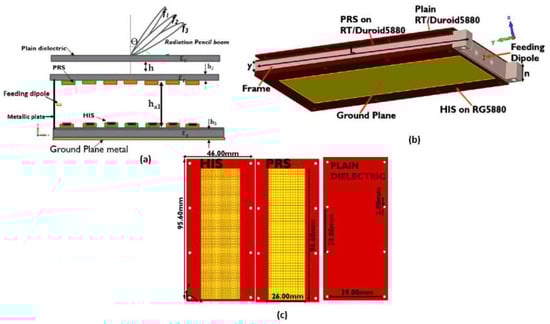
Figure 46.
Structure of a leaky wave antenna (LWA): (
a
) geometry; (
b
) 3D view; (
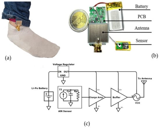
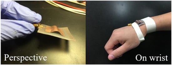
Figure 57 depicts an industrial scientific and medical (ISM) sub-6 GHz wearable sensor device for heart rate monitoring [5][56]. This frequency range provides the best trade-off in terms of the footprint, bandwidth, and communication range of all the bands that are currently available worldwide. Frequencies below 2.4 GHz are unviable as they increase the antenna footprints and decrease the range of reserved bands. Moreover, an issue of overpopulation is encountered owing to the multitude of communication protocols operating within this band. Frequencies above 6 GHz are ill suited for long-distance communications (mm-waves) owing to increased attenuations and coherence issues.
With the smartphone market reaching saturation, a new trend is emerging in the field of personal mobile devices, known as wearable mobile devices or simply wearables [6][19]. These devices come in various forms that are designed to be worn as accessories or clothing. Despite their small size, they are expected to continuously collect and transmit physiological data to enhance the quality of life. Consequently, wearable systems require improved communication security and reduce power consumption, thus prompting research efforts in these domains [7][57].
A wearable antenna with a small feeding network was discussed in [8][61]. The antenna used the aperture coupling technique. This design reduces the size of the rigid printed circuit board (PCB) that carries the electronic circuits and feeds the textile antenna, thereby improving user comfort. Additionally, it eliminates the need for probe feeding, which involves a single soldering point that is susceptible to breakage over time owing to user movements. A high manufacturing precision can be ensured using an aperture on the PCB. The antenna had a compact feeding network measuring 10 × 10 mm2 (0.0817 × 0.0817 λ02 at 2.45 GHz) and maintained a good performance in the ISM band.
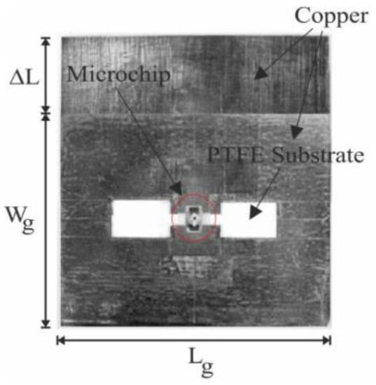
In [9][62], a dumbbell-shaped ground plane for the antenna ground was employed to optimize the radiation patterns. In Figure 68 a comprehensive analysis of the antenna in terms of the electric and magnetic energies around the antenna borders was conducted [9][62]. Various ground-plane structures were proposed to analyze the energy density around the radiating surface and assess whether it withstands the coupling between the antenna and human.
Antennas employed in short-range near-field ultra-high frequency (UHF) radio frequency identification (RFID) systems are typically positioned close to the human body [10][63]. This implies that the designer must ensure that the antennas are robust and shielded from body coupling effects. For grounded antennas, a specific criterion can be used to determine the appropriate shape and size of the antenna ground plane. In [10][63], Near-field region characteristics of the grounded antenna on the human body are measured. From the observed SAR value, the robustness of the antenna against body coupling effects can be ensured without significantly altering the size of the antenna.
The design considerations for a UHF band card-type tag, which was enclosed in a packet and placed near the chest for applications on theour university campus, were discussed in [11][64]. The FEKO simulation tool was used to design four different types of tag antennas that are highly insensitive to platforms [11][64]. Additionally, they measured the input impedances of the tag antennas using a test fixture and a two-port network analyzer to validate the simulation results and confirm the reliability of the simulation tool.
Recently, body-centric wireless communications have gained considerable interest. A small and efficient planar inverted-F antenna (PIFA) that operates at 2.45 GHz for on-body communications was introduced in [12][65]. The antenna consisted of two shorting structures and a folded ground plane, which enhanced impedance matching and reduced the antenna size. Hence, the antenna was compact and maintained a low-profile even when it was positioned in close proximity to the human body. The study examined the antenna’s performance near an arm phantom through simulations and experiments. The results from both methods align well.
A flexible antenna operating at two frequency bands was proposed for data transmission. The antenna had a low profile and a size of 35 × 20 mm2. It was fed using a co-planar waveguide (CPW) [13][66] and operated at 2.44 and 5.8 GHz in the ISM radio band. The antenna had a Rogers Ultralam 3850 substrate, which made the antenna highly flexible. The antenna’s compact size, flexibility, and dual-band resonance in the ISM band make it well suited for wearable applications. Table 1 depicts the various substrate materials used for wearable antenna design.
Table 1.
Types of substrate materials commonly used for wearable antennas.
| Type of Substrate | Dielectric Loss | Dielectric Constant | Thickness (mm) |
|---|---|---|---|
| Cotton/polyester | 0.02 | 1.6 | 2.8 |
| Woolen felt | 0.02 | 1.6 | 3.5 |
| Fleece fabric | — | 1.25 | 2.56 |
| PEN | 0.025 | 2.9 | 0.125 |
| Cordura | 0.0098 | 1.1–1.7 | 0.5 |
| Felt | 0.02 | 1.3 | 1.1 |
| PDMS-MCT | 0.015 | 3.8 | — |
| PET | 0.008 | 3 | 0.14 |
| Liquid crystal polymer (ULTRALIM 3850) | 0.0025 | 2.9 | 0.1 |
| PDMS with glass microsphere | 0.014 | 1.85 | — |
| Polyimide | 0.005 | 2.91 | 0.2 |
| PDMS | 0.02 | 2.65 | — |
| PDMS with silicate microsphere | 0.02 | 2.45 | — |
| PDMS with phenolic microsphere | 0.022 | 2.24 | — |
| Paper (Kodak photo paper) | 0.05 | 2.85 | 0.254 |
2. Textile Antenna
A compact, flexible wearable antenna composed entirely of a textile material for the 2.45 GHz ISM band was discussed in [14][67]. It comprised a monopole radiator and a 2 × 1 EBG array, rendering it well suited for wristband applications [14][67]. The EBG unit cell was optimized for the desired operating band and further modified to maximize the bandwidth. The monopole radiator works in conjunction with the EBG layer to induce resonance in the ISM band with good radiation characteristics. Figure 79 shows the design of the antenna, whose dimensions are Gy = 10 mm, Ax = 35 mm, Ay = 52 mm, W1 = 28 mm, W2 = W3 = 4 mm, H1 = 7 mm, H2 = 13 mm, H3 = 6.42 mm, R = 5 mm, Fx = 2.5 mm, Fy = 26.12 mm, Ey = 35.4 mm, Uh = 5, and d = 1.9 mm, respectively. After fabrication, the performance of the antenna was tested in a free space and against human body loading. The antenna exhibited a bandwidth in the range of 2.39–2.54 GHz and had a compact size of 35.4 × 82.4 mm2. Experimental tests showed that the antenna maintained its performance when positioned near to the human body. The antenna exhibited a safe SAR of 0.297 W/kg at a 0.5 W input power, thus indicating that the antenna can be used safely in wearable devices.
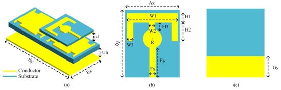
Figure 79.
Wearable antenna: (
a
) 3D view with all layers; (
b
) front view of the antenna; (
Another previous study [15][68] discussed a technique for enhancing impedance matching in a low-profile loop antenna using a high-impedance surface (HIS) structure, as shown in Figure 810. The loop antenna was designed to be wearable, and it is intended for healthcare applications. First, the study examined the impact of various textile parameters on the performance of the loop antenna, both through numerical simulations and experimental tests. Subsequently, it applied the proposed technique and validated the simulation results with the experimental results. Compared with a standalone loop antenna, the loop antenna with the HIS structure exhibited an improved matching performance in the 2.45 GHz band. In general, it also exhibited satisfactory far-field properties and a maximum gain of 6.19 dB. Additionally, the study investigated the effects of bending the loop antenna, both with and without the HIS structure, as well as its proximity to a modeled human arm. The wearable antenna with the HIS structure showcased commendable performance in these scenarios.
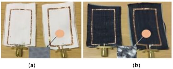
Figure 810.
Textile antenna in which a slot is introduced for impedance matching on (
a
) cotton material and (
A small textile antenna was designed and tested for use in the ISM band at 2.4 GHz. The antenna utilized a rectangular slot/notch with a strip line inserted to form an inverted E-shape [16][69]. This design is simple, compact, and easily manufacturable using fabric materials. The antenna was 75% smaller than traditional antennas and maintained its performance even when it was bent. The equivalent circuit of each slot/notch and the strip line was determined and integrated to derive the overall equivalent circuit of the antenna. The results derived from the equivalent circuits were consistent with the simulation results. The antenna had dimensions of 30 × 20 × 0.7 mm3 and exhibited an impedance bandwidth of 15% and an efficiency of 79%. These findings indicate that the antenna holds significant potential for use in wearable systems.
A wearable microstrip antenna made from conductive textile fabric was introduced in [17][70]. It was designed for communications in multiple ISM bands. The antenna operated at three frequencies, 2.450 GHz, 4.725 Hz, and 5.800 GHz, and it was composed of a silver fabric patch and ground plane mounted on a flexible low-permittivity foam substrate [17][70]. A copper reference prototype was fabricated to validate the design. The experimental results from the two antennas show the expected resonances; however, some unexpected loss was observed, particularly at high frequencies. The simulation results for the antenna performance under different bending conditions demonstrate that the design is robust, with the resonant frequencies deviating within an acceptable range.
Recently, fabric and textile antenna designs have gained widespread attention owing to the growing demand for multi-frequency and multi-function antennas in smart clothing and future consumer-centric communication technologies [18][71]. The mode of fabrication and materials used play a crucial role in determining the performance of these antennas. A previous study [18][71] examined the influence of fabrication methods and materials on the performance of a rectangular microstrip patch antenna. The study aimed to realize antennas that are cost-effective, easy to integrate into systems, and capable of maintaining their performance when worn on the human body.
The performance of an antenna equipped with a textile substrate and an AMC was discussed in [19][72]. This study proposed a method of obtaining single- and dual-frequency resonances using two different textile materials, namely denim and flet. The antenna element was engraved on the textile materials using the electro-textile method to impart flexibility to the antenna. The hexagonal AMC structure acts as the reflector, which reduces the backward radiation and protects the human body during radiation. The antenna operated in the broadband frequency and was fed using a CPW.
The biological attributes of the human body, such as tissue properties and skin layers, play a crucial role in determining the propagation of radio signals through the human body [20][73]. A textile monopole antenna operating at 2.45 GHz was tested on different subjects to analyze its radiation effects. The results indicate that the antenna was resilient to changes induced by the human body: only 0.9% and 0.2% shifts in the impedance matching level and resonant frequency were observed, respectively, when the antenna was placed 10 mm away from the body. The antenna was composed of a ripstop and woven polyester fabric coated with copper and nickel. It had a thickness of 0.17 mm and weighed approximately 230 g/m2. According to the manufacturer, the surface resistance of the fabric was below 0.05 Ω/sq.
Antennas employed for healthcare applications usually operate in multiple band frequencies. A reconfigurable patch antenna is well-suited for biomedical applications. In [21][74], a compact button-shaped dual-band antenna for frequency reconfigurability was discussed. The proposed antenna operated in the 2.45 and 5.8 GHz unlicensed bands. Next-generation wearable textile antennas are expected to be body-worn radiating elements operating under the unlicensed frequencies of 2.45 and 5.8 GHz. The compact antenna was printed on a jean substrate with dimensions of 42 × 13 × 1.5 mm3, and it exhibited an omnidirectional radiation pattern. The study assessed the performance of the antenna in both a free space and human body surface. Owing to its compact size, this antenna may find utility in numerous applications within the smart wearable textile industry.
A planar inverted-F antenna (PIFA) is the most preferable radiating element for transmitting signals in portable wireless devices. In [22][75], the performance of a PIFA was evaluated for various distances between the human body and antenna and its scattering effects on human tissue. The study also investigated the near-field, electric, and magnetic-field distributions of the radiating patch. The antenna–body coupling was mitigated by adjusting the antenna ground plane, which enhanced the effectiveness of the antenna.
Several wearable antennas that are resistant to the body coupling effect have been reported in the literature [23][76]. To achieve this resistance, an antenna must maintain good input matching and efficiency even when positioned in close proximity to the human body. In [23][76], the efficiency of complimentary structures in coupling with the human body was evaluated and compared. Two body-worn antennas were highlighted: a printed patch antenna with a meandered ground and a meandered slot antenna with an ungrounded surface. According to theour research, magnetic antenna designs, such as meandering slot printed antennas, are favored for wearable systems, even though similar structures are virtually comparable in non-wearable systems. Through careful design considerations, the susceptibility of these antennas to human body proximity can be mitigated substantially through careful design decisions.
Wireless technology is integral to the advancement of flexible and stretchable electronics, which has gathered attention in view of addressing the increasing demand for devices that are compact, portable, and comfortable [24][77]. Microstrip antennas have emerged as promising alternatives in the realm of wireless technology, owing to their high flexibility and advanced bending electronics assembly. However, the flexible nature of microstrip antennas often entails a decrease in their conductivity and radiation efficiency. To address this issue, two designs were proposed: the stretchable mesh microstrip antenna and the arch-shaped microstrip antenna. Both antennas employ a silicone substrate, which is sandwiched between conductive materials. The resonance frequency of the antennas varies with respect to the bending condition. However, the variation depends on the strain of the antenna element. The resonance frequency of the meshed microstrip antenna decreases as the antenna strain increases. The strain of the arched antenna must be decreased considerably to increase its resonance frequency. Among the two antennas, the microstrip antenna exhibits a higher sensitivity to strain, with the resonance frequency exhibiting 3.35- and 1.49-fold increases. The proposed antenna is adaptable to ultra-wideband (UWB) bandwidth, and it rejects the high frequencies in the UWB range. Additionally, the antenna performs well when placed on the body, thus making it a promising candidate for wearable applications is shown in Figure 911.
3. Polymer Based Antenna
In [25][78], the properties of a silicone-based polymer polydimethylsiloxane (PDMS) substrate were examined to assess its applicability for realizing flexible and wearable antennae and sensors. First, the substrate was developed, ensuring that it satisfied the necessary requirements as shown in Figure 102. Subsequently, its anisotropy was examined through a bi-resonator experiment. The material showed a noticeable but moderate level of anisotropy: the dielectric constant and loss tangent exhibited anisotropy values of approximately 6.2% and 25%, respectively [25][78]. The anisotropic behavior was confirmed by the following: the dielectric constants in the parallel and perpendicular directions were approximately 2.717 and 2.570, respectively, with the former being higher than the latter by 5.7%. The dielectric properties of the PDMS substrate were found to depend on the temperature. Additionally, the study investigated the combined effect of bending the PDMS substrate and its anisotropy on the resonance properties of planar structures. These two factors induced opposing effects. Based on the experimental results, PDMS is a strong candidate as a substrate for flexible and wearable antennas and sensors.
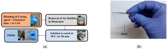
Figure 102.
Polymer-based flexible antenna: (
a
) stepwise process of preparing polymer material; (
Owing to rapid advancements in wearable electronics, flexible radio-frequency wireless antenna sensors have garnered considerable interest for their various IoT applications [26][79]. However, the miniaturization and flexibility of antenna sensors are impeded by device configuration and material issues. In [26][79], a wireless sensor that utilizes a microstrip antenna, which is composed of a copper ground plane, a PDMS dielectric substrate, and an MXene patch, is proposed. The optimized device is compact (40 × 40 mm2) and operates at a resonant frequency of 4.8 GHz, with a frequency shift range of 8% under different strains. Additionally, it is compatible with 5G communications. Additionally, the sensor exhibits excellent mechanical flexibility and maintains a stable response to repetitive stimulations. It exhibits a superior strain sensitivity of 20 compared with similar antenna sensors. Its resilience to human body proximity was tested by performing cantilever motion monitoring. The antenna exhibits satisfactory stability and sensitivity. It exhibits noticeably shifted resonant frequencies while maintaining a reflection coefficient of approximately −25 dB, indicating its potential for applications in the fields of healthcare monitoring, construction diagnosis, and IoT.
A smart pH measuring device can provide vital health information and has various applications in detecting infections, diagnosing diseases, and personalized medicine [27][80]. However, such devices are often expensive, have limited flexibility, and require large instruments to read the results, which render them ill suited for wearable, remote, and continuous health monitoring. In [27][80], a novel wearable sensor system, referred to as WB2F3D, is discussed. This sensor is a miniaturized and modular 3D-printed system. The system facilitates the on-demand, continuous, wireless, and real-time monitoring of pH levels. The sensors, electronic circuits, and antennas are printed using nanomaterials on flexible substrates, which facilitates multimaterial and multilayer printing in a cost-effective and efficient manner. The readout system is designed to be battery-free and flexible, enabling the wireless transmission of signals and data for continuous and real-time pH monitoring. The sensor system has a high sensitivity, specificity, repeatability, and reproducibility across various pH ranges. It is also mechanically flexible and biocompatible, as evidenced by a cell viability of at least 90%. The system successfully monitored the pH change in a wound model. The sensor system is expected to provide an integrated platform for accurate, on-demand, battery-free, wireless, and real-time monitoring of human health, bringing society closer to personalized medicine.
Interdisciplinary research focuses on routine healthcare objects to develop sensors that can monitor human biomedical parameters in an ergonomic and environmentally sustainable manner. In [28][81], a hybrid system that combines the solution-processed and conventional silicon technology is presented. A strain and pH sensor based on graphene ink is used, while a poly(3,4-ethylenedioxythiophene)–poly(styrenesulfonate) (PEDOT: PSS) sensor is used to detect humidity. These sensors are integrated into a demonstrator that is equipped with a silicon near-field communication transponder chip with logic processing and transceiver capabilities. The chip is bonded to a circuit board containing components that are inkjet-printed on a paper substrate, including the antenna, power supply, and sensors. This proof-of-concept study aims to meet the requirements of a future circular economy and provide a cheap, flexible, lightweight, and multi-functional electronic device.
In the past few decades, considerable efforts have been spent to develop simple and cost-effective methods for preparing superhydrophobic membranes using PDMS. In [29][82], a straightforward approach is presented to electrospin a PDMS membrane, using poly(methyl methacrylate) (PMMA) as a carrier polymer. The researchers investigated the effects of the PMMA concentration, PDMS/PMMA mass ratio, and key parameters of the electrospinning process (voltage and injection rate) to realize a superhydrophobic membrane that exhibits a high water contact angle (WCA). The highest WCA (163°) was achieved for the membrane surface that was electrospun with a solution containing PDMS, PMMA, tetrahydrofuran (THF), and N-dimethylformamide (DMF) in a mass ratio of 1:1:8.88:9.48. The process was conducted at an applied voltage and injection rate of 11 kV and 0.1 mm/min, respectively. The superhydrophobic PDMS/PMMA membrane was then used to conduct a membrane distillation process for desalination, and a high permeation flux of 39.61 L/m2 and an excellent salt rejection rate of 99.96% over a 24 h period were achieved.
Another previous study [30][83] discussed the development and analysis of a wideband antenna based on a PDMS composite. The metallic parts of the antenna were formed by incorporating conductive fibers into the PDMS composite. The performance of the antenna was compared with that of a traditional antenna composed of conventional dielectric materials. Both antennas exhibited a good matched bandwidth; however, the PDMS composite antenna showed reduced radiations towards the broadside direction, particularly at high frequencies. The antenna exhibited a matched bandwidth of 59.9%, covering a frequency range of 3.43–11.1 GHz. Additionally, the antenna’s flexibility was tested under different bending conditions. The wideband behavior was well maintained with a maximum variation of 1%.
A polymer-based flexible antenna that operates at three different frequency bands (5, 5.8, and 6.6 GHz) for WLAN and WBAN applications was developed in [31][84]. The antenna is fed by a CPW and has dimensions of 50 × 40 mm2. The antenna uses a PDMS substrate with a dielectric constant of 2.65 and a loss tangent of 0.02. The antenna has a rectangular slot on the ground and a single circular SRR on the patch. The SRR structure assists in achieving the desired frequency notching characteristics, compact size, minimal losses, and reduced backward radiation when the antenna is used near the human body. The proposed flexible antenna showcases a stable performance and a low SAR. The antenna performance was also evaluated under various moisture and bending conditions. The simulation results are consistent with the measured data.
Modern wearable health monitoring systems utilize multiple biosensors embedded in wireless devices [32][85]. This necessitates new antenna design requirements to ensure the reliable transmission of vital signs. Hussain et al. introduced a flexible, compact, and ultra-low-profile dual-band antenna. Its design is suitable for wearable and flexible telemedicine systems, as well as WBANs. Using the inkjet technology, the antenna is printed on a 50.8 μm polyimide Kapton substrate and is fed by a CPW. The proposed design offers advantages such as compactness, a light weight, wide bandwidth, high efficiency, and high mechanical stability. Additionally, the antenna’s performance was evaluated under bending and rolling conditions to simulate real-world usage on curved surfaces. The results indicate that the antenna is highly resistant to performance degradation resulting from bending. The proposed design is a viable option for the intended application owing to its favorable radiation characteristics, simplified fabrication process, cost-effectiveness, and excellent physical properties.
Another study [33][86] focused on the potential of integrating a highly conductive fabric into composite materials via an efficient fabrication technology. It aimed to fabricate a flexible composite antenna with high radiation performance. The process involved embedding a thin sheet of a conductive fabric into a composite laminate made of E-glass fiber mat and epoxy resin. The antenna elements were precisely machined via laser etching. The antenna exhibited a radiation efficiency of over 70% across its operating frequency range, with satisfactory radiation patterns and gain. The composite antenna performed well under different bending conditions. This study demonstrated the promising potential of integrating efficient antennas into various devices and objects made of composite laminate materials. The proposed fabrication technology was validated through the design and fabrication of a UWB antenna, and its performance was compared with that of a reference antenna comprising a copper sheet printed on the same composite dielectric substrate.
Another study [34][87] proposed a novel approach of integrating an ionic polymer metal composite (IPMC) actuator with an RFID tag antenna to achieve frequency reconfiguration in the UHF band. The IPMC actuator is shaped like a movable flap and is used to effectively tune the resonant frequency of the tag. To improve the deflection of the IPMC actuator, a two-layer crenelated structure and a surface patterned electrode are employed to restrain back relaxation. The IPMC actuator can move in two directions, which facilitates two-degree frequency tuning. The numerical and experimental data show that the displacement of the IPMC actuator tip can be increased by up to 266% using the two-layer crenelated structure. Using the IPMC actuator, the resonant frequency of the tag antenna can be adjusted by as much as 35 MHz, effectively correcting any frequency deviation caused by the unintended placement of the antenna on an object. The performance of the tag antenna was evaluated using a portable commercial RFID reader. The antenna exhibited good frequency reconfiguration, a broad tuning range, and long read distances.
PDMS is a versatile elastomer that possesses exceptional optical, electrical, and mechanical characteristics, rendering it highly suitable for various engineering applications [35][88]. Its biocompatibility has made it a popular choice in the biomedical field. Consequently, the soft lithography technique, which primarily utilizes PDMS, has been widely adopted for the rapid prototyping of micro and nanostructures. This technique has significantly contributed to advancements in microfluidics, electronics, and biomedicine. Another study [35][88] provided an overview of PDMS properties and commonly used PDMS treatments, emphasizing their applicability to the aforementioned fields. Additionally, it examined specific PDMS applications such as biomedical microchips, the replication of cardiovascular flow, and medical implants.
A new UWB antenna was developed for wearable applications in the 3.7–10.3 GHz band [36][89]. This antenna is designed to be flexible and resistant to human body loading and physical deformation. It has a size of 80 × 67 mm2 and is composed of a simple microstrip structure with two modified arc-shaped patches as the main radiator. The antenna also includes a full ground plane on the opposite side of the substrate to prevent interference from biological tissues and back radiation towards the human body. To ensure flexibility and durability, the antenna is fabricated using conductive fabric embedded into a PDMS polymer. The simulation and experimental results reveal that the antenna exhibits promising performances in both free-space and in vitro on-body cases. This is the first UWB antenna with a full ground plane that can withstand the harsh conditions that are typically encountered with wearable applications.
A flexible UWB antenna using a PDMS substrate was proposed in [37][90]. The conducting layers are composed of a 0.193 mm thick copper foil, and the overall thickness of the antenna is 1.886 mm. The antenna is designed to cover a frequency from 1.5 GHz to above 15 GHz. The performances of the antenna at specific frequencies (1.8, 2.4, 3.6, 4.2, 4.8, 5.2, and 5.8 GHz) were analyzed and compared. The SAR at these frequencies was evaluated and was found to be below the recommended value of 1.6 W/Kg. The performance of the antenna was assessed in terms of various parameters such as the reflection coefficient, VSWR, impedance, gain, surface current distribution, far-field radiation pattern, and the SAR. This study also discussed the use of a 1.5 mm thick PDMS layer as the substrate and a 0.193 mm thick copper sheet as the conductive layer for the radiator and ground. The performance of the antenna with and without bending was evaluated. The SAR and far-field analysis were conducted using layered phantom and human phantom models to determine the suitability of the antenna for body-worn applications.
The abrasive jet machining (AJM) of PDMS is either slow or impossible at room temperature because PDMS can absorb the energy of the impacting particles. In [38][91], cryogenic AJM was employed to increase the material removal rate; however, its efficiency depended on the mechanical performance of the PDMS samples. The samples were tested for compressive strength, hardness, X-ray diffraction, and linear expansion coefficient according to GB standards. The compressive modulus, ultimate compressive strength, and hardness of the samples were in the ranges of 17.31–1160.1 MPa, 160.25–224.50 MPa, and 43–90.67 ShD, respectively. They exhibited a coefficient of thermal expansion (CTE) of 247 × 10−6 1/K at different temperatures from 103 K to room temperature (RT = 298 K) to 123 K. The results show that as the temperature decreased, the failure mode of PDMS changed from ductile to brittle, with evident brittle characteristics at 123 K.
Another study [39][92] summarized the bending capabilities of flexible polymer substrates for general IoT applications. It explored the use of various flexible materials such as polymers, plastics, paper, textiles, and fabrics in wearable sensors is shown in Figure 113. It provided a chronological order of the flexible materials used in the past few decades and discussed their flexibility, bending ability, and resistance to deformation. In the future, IoT is expected to rely on wireless connectivity and support a wide range of technologies. Therefore, flexible materials with bending capabilities are crucial for realizing wearable IoT devices. The study examined commonly used polymer substrates and compared their physical, electrical, and mechanical properties. Additionally, it investigated the impact of bending on the radiation performance of antenna designs based on polymer substrates. It focused on the use of flexible materials such as polyimides (PI), polyethylene terephthalate (PET), PDMS, Polytetrafluoroethylene (PTFE), Rogers RT/duroid, and liquid crystal polymer for realizing flexible antennas in IoT applications. The study investigated the effects of bending and folding on radiation characteristics such as S-parameters, resonant frequency deviation, and impedance mismatch with the feedline of the microstrip antennas. These flexible polymer substrates hold promising potential for future wearable devices and general IoT applications.
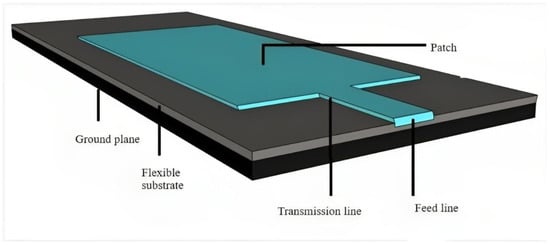
Figure 124 is the compact flexible antenna was specifically designed for body-worn devices. To ensure the comfort of use and antenna flexibility when the antenna is in contact with the human body, a substrate made of natural rubber filled with TiO2 was developed [40][93]. The antenna was miniaturized using the quadratic Koch curve. The design, optimization, and characterization of the antenna were conducted using a human body model. The performance of the antenna was evaluated in terms of in-body and off-body wireless communication capabilities. The results indicate that the maximum telemetry range of the antenna for in-body and off-body communications exceeded 80 mm and 2 m, respectively. Additionally, the highest SAR value shown was 0.62 W/kg. With its compact dimensions (12 × 26 × 2.5 mm3) and low manufacturing cost, this antenna is well suited for health telemetry applications. Compared with other flexible antennas, the proposed antenna demonstrates smaller dimensions, better radiation efficiency, and higher gain when placed on a human body model.
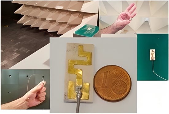
A modified sinusoidal half-wave dipole antenna sensor that can be used for strain sensing applications was discussed in [41][94]. Figure 135 is an antenna with improved version of a sensor that was previously introduced for respiration monitoring. The study examined the electrical and radiative characteristics of the sinusoidal antenna and the effects of various geometrical factors. It provided a design approach and equations to estimate the geometrical parameters according to the desired electrical specifications. The results show that the sensitivity of the antenna sensor can be up to 5.5 times higher than that of the previous generation. The use of a conductive polymer material for the fabrication of the antenna can render the antenna more flexible and durable compared to a glass-based antenna.
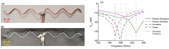
Figure 135.
Fabrication and comparison: (
a
) copper metal antenna; (
b
) polymer antenna; (
4. Antennas for Microwave Imaging
Microwave imaging is an efficient method used to diagnose cancer in its early stage. However, the efficiency of a microwave imaging system depends on the effectiveness of the antenna used for transmitting and receiving the microwave signals. Moreover, the antenna should be flexible. Extensive research has been conducted on designing a flexible antenna and increasing its efficiency to save the lives of people. An early detection of cancer can significantly enhance the chances for recovery, potentially saving numerous lives. In India, almost 2.5 million cancer patients have been registered, with 1 lakh new cases added annually. In 2018, 7 lakh deaths occurred owing to cancer. According to the Indian Council of Medical Research, India is likely to record over 17 lakh new cancer cases with over 8 lakh deaths by 2022. Breast cancer is the most prevalent type of cancer in women. These statistics underline the necessity of developing new methodologies for the early detection of breast cancer. Currently, image processing techniques, such as mammography, magnetic resonance imaging, and ultrasound, are available for breast-cancer diagnosis. To improve the efficiency of early breast cancer detection, a portable breast cancer detection device using the microwave imaging technique can be designed and developed. It involves designing a flexible wearable metamaterial antenna operating in a UWB frequency range and machine learning techniques. In addition, a flexible wearable metamaterial antenna can be used as a wearable device to address the limitations of the current detection technologies, which involve radiations that are painful and detrimental to the human body [10][42][43][44][63,95,96,97].
A U-shaped slot for ultra-wideband microwave imaging applications was proposed in [45][98]. The antenna consists of a tapered slot and star patches located on both the top and ground planes. The star patch located at the side of the feed line improves the impedance matching for the operating frequency band. The addition of a rectangular slot at the U-shaped slot improves the resonance at the lowest frequency, as shown in Figure 146. The tapered section containing the star shape patches at the bottom layer increases the antenna bandwidth from 3.8 to 10.1 GHz. A heterogenous phantom mimicking a human breast, with tumors introduced within the breast tissue, was developed and experimentally tested. The radiation characteristics of the antenna were evaluated in terms of the fidelity factor. Fidelity factors of 91.6% and 91.2% were observed for the face-to-face and side-by-side orientations, respectively. This implies that the antenna has good directional radiation.
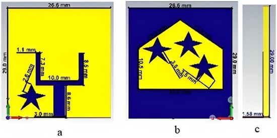
Figure 146.
Ground plane and star patch: (
a
) U-shaped ground plane; (
b
) star patch on the top plane (
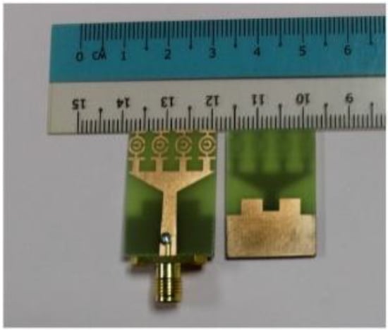
A printed monopole antenna was designed with staircase steps at the edge of the feed line, as shown in Figure 157. This antenna has dimensions of 40 × 36 × 1.6 mm3 and uses an FR4 substrate [46][99]. The operating frequency range and resonance can be varied by altering the monopole edges. The dimensions of the antenna were derived using the general transmission line model. Increasing the length of the current flow path in the antenna layout more easily simplifies the operation of the antenna in the low frequency despite its miniaturization. In the proposed antenna, one step is cut at the edge near the feed line and a slot is made at the bottom plane, which introduces impedance matching in the operating frequency range. The monopole antenna operates between 2.7 and 11.4 GHz and has a moderate gain in the range of 1–6.5 dBi. Figure 168 depicts the four-monopole antenna surrounding the human phantom model to study the performance of the antenna on a human body.
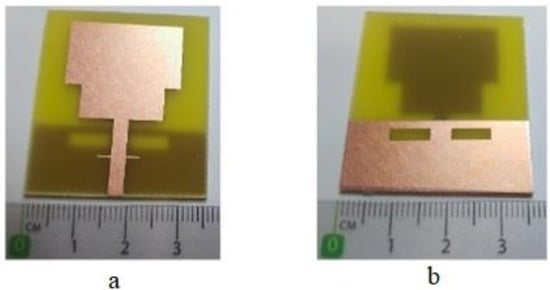
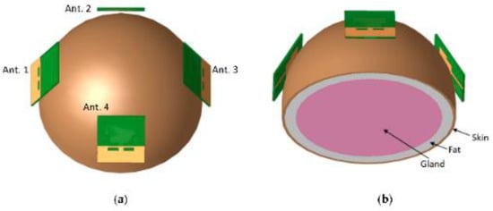
Figure 168.
Simulated four-antenna elements around the human phantom: (
a
) top view of antenna arrangement and (
Metamaterials are remarkable engineering novelties, and they are shown in Figure 179. They can exhibit rare electromagnetic properties such as a negative refractive index. Negative-index or left-handed metamaterials and double-negative metamaterials are types of metamaterials that simultaneously exhibit negative permeability and negative permittivity. Their invention has paved the way for the development of microwave devices such as antenna sensors. Further, they can be used as regeneration systems in microwave imaging. The unit cell is a complementary SRR structure printed on a 1.6 mm thick FR4 structure [47][100]. The proposed SRR unit cell exhibits peak transmissions at 8.9 GHz, which indicates left-handed characteristics. One-element and four-element metamaterials have been proposed for UWB applications. A defective ground structure introduced in the ground plane optimizes the surface current in the patch antenna, which increases the operation frequency from 3.1 to 10.6 GHz.
In [48][101], a modified, small, flexible Vivaldi antenna with dimensions of 25 × 20 × 0.1 mm3 was proposed and examined, and it is shown in Figure 1820. Two antenna designs were examined; one has a resonant frequency at 4.4 GHz, and the other has a resonant frequency at 9.4 GHz. The antenna was fabricated via the conventional PCB manufacturing method and uses a flexible material (polyimide) with a dielectric constant of 3.5 and a thickness of 0.1 mm [48][101]. With an array of nine identical 4.4 GHz antennas, a microwave radar-based imaging toolbox was employed to detect and pinpoint tumor cells inside a layered phantom model. The simulation results show that tumors of various sizes and positions within the phantom model can be successfully identified and located using the proposed method. The proposed microwave imaging technique is a viable method for the early diagnosis of breast cancer, and the proposed Vivaldi antenna is the most suited for breast imaging applications.
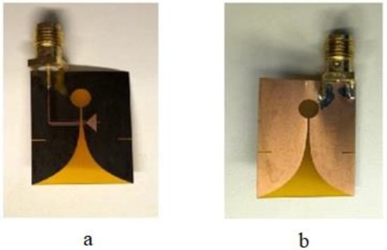
Figure 1820.
UWB Vivaldi antenna for microwave imaging applications: (
a
) bottom layer with feed line and (
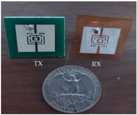
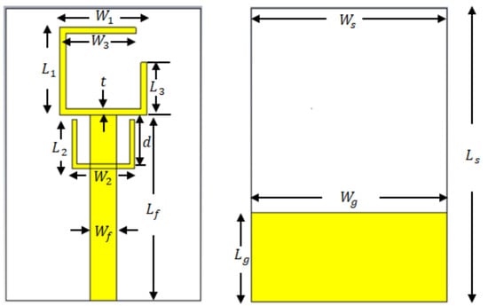
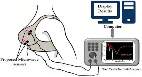
In [49][102], a biodegradable textile material and a conformal microwave sensor equipped with a circularly polarized antenna are presented, which has diverse medicinal applications. The proposed sensor consists of a monopole antenna printed on a textile substrate. The antenna has an overall size of 33.5 × 33.5 mm2 (0.2 λo × 0.2 λo) and is fed using a CPW as shown in Figure 219 [49][102]. A silver conductive fabric forms the radiating area and bottom ground, which are then stitched on a 2 mm thick cotton substrate. A slot is introduced into the radiating element to increase the bandwidth from 1.8 to 8 GHz. Near-field microwave scanning was employed to investigate both the on-body and off-body (air) performances of the proposed Circularly Polarized Microwave Sensor (CPMS) near human models with and without malignancies. The axial ratio is one of the major characteristics of a circularly polarized antenna and provides an additional degree of accuracy for data processing and cancer diagnosis. To ensure safe operations, the radiation characteristics of the device were recorded, along with its SAR. Consequently, the number of data samples increased, which helped to improve the detection efficiency. The proposed device was designed to assist women with the early detection and continuous monitoring of breast cancer in the convenience of their homes.
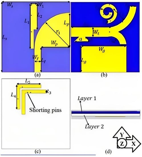
In [50][103], a small, wearable dual-polarized MIMO antenna is described. Dual polarization is achieved using tree-shaped and leaf-shaped antennas, which are horizontally and vertically polarized, respectively. The coupling effects at the desirable resonances are eliminated by implementing stubs, a parasitic spiral, and shorting pins [50][103]. The ShieldIt conductive textile is used in conjunction with a dual-layer substrate. The substrate has a felt layer and denim layer, whose dielectric constants are 1.8 and 1.2, respectively, with thicknesses of 0.9 and 0.5 mm, respectively. To obtain three additional cells, the dual-port MIMO unit cells were rotated 90° and separated by 2 mm, as shown in Figure 202. The antenna bandwidth satisfying the SAR standards for 1 and 10 g of tissues is between 4.8 and 30 GHz. After combining the shorting pin and spiral parasitic loadings, an isolation exceeding 18 dB was attained and a reduction in mutual coupling was observed. Both the on-body (breast) and free-space performances of the antenna were evaluated via near-field microwave imaging. Based on the appropriate operation frequency, low SAR, high fidelity, and high accuracy in tumor location, the proposed dual-polarized MIMO structure is a respectable option for breast tumor imaging.
Several numerical techniques were reported for antenna miniaturization based on patch antenna loading with slots, lumped elements, and shorting posts. The slots introduced are of various shapes, and the lumped elements, based on similar reactive components, are designed at the resonating frequency. The etching of various slots facilitates the reduction in the antenna size for modern wireless communication [51][104].
Antenna miniaturization is accomplished by fabricating a patch structure on a dielectric substrate with a dielectric value that is higher than that of the patch. However, this drastically increases the current distribution and leads to surface wave effects, which degrade the patch antenna characteristics such as the impedance bandwidth, radiation characteristics, and radiation efficiency [52][105].
Currently, UWB antennas are the most preferred antennas for non-destructive testing and microwave imaging. UWB antennas operate in the frequency range of 3.1–10.6 GHz, which encompasses low-frequency to very-high-frequency signals; hence, the use of UWB antennas produces images with better resolution. A device for obtaining the three-dimensional scan of a breast model was developed in [15][68]. The device employs a confocal microwave imaging algorithm to illuminate the breast organ and record details regarding tumors, skin, and healthy tissue [53][106].
Employing notch cutting in the ground plane reduces the effects at low frequencies. Impedance matching is provided for the input feed from the finite ground plane, and slots are introduced in the radiator. This prompts the antenna to radiate in the UWB frequency range [54][107]. The cancerous and healthy tissues are differentiated using a hybrid imaging modality in the microwave range and its performance is assessed using the Debye testbed setup [55][108]. A UWB monopole antenna with multifractal edges provides an improved impedance bandwidth across the operating frequencies [56][109]. Transverse electromagnetic horn antennas were tested using a compressed heterogeneous breast model for near-field microwave imaging [57][110]. Breast cancer detection based on UWB microwave imaging is used for early detection; however, the method is hindered by drawbacks due to complex algorithms. Machine learning methods assist in detecting cancer cells of smaller sizes, which may improve the accuracy of the results [58][111].
Recently, digital mammography has been adopted for breast cancer detection. Digital mammography is almost similar to the traditional method of film screen mammography. However, the latter involves compressing and positioning the breast organ over the mammography machine in a manner that may be painful for the patients. Digital mammography primarily aims to detect breast abnormalities. Compared to the conventional method of mammography, digital mammography provides breast images with a better resolution at lower radiation levels. However, it suffers from high false positive and negative rates. This necessitates additional examinations to confirm cancer and higher expenses for the early diagnosis of breast cancer. A flexible wearable patch antenna with a jean substrate is proposed in [59][112]. This antenna operates at 5.8 GHz.
The conductivity of the electro-textile material and its surface impedance was measured. Furthermore, the SAR analysis was conducted. The antenna exhibited increased bandwidth and efficiency. A metamaterial antenna was fabricated using a low-cost FR4 material, and the antenna characteristics were evaluated by applying metascreens over the patch.
In [60][113], the use of the above antenna for wireless applications is discussed. The body-centric performance of various conventional wearable designs, textile antenna designs, conductive materials, and fabrication methods were analyzed to assess their potential for wireless applications. The effect of bending and on-body performance were also assessed.
In [61][114], a radar-based UWB microwave imaging technique based on the dielectric properties of the human breast tissues is investigated. In [62][115], the performance of miniaturized flexible antennas placed at various positions on the breast is analyzed. A moderate dielectric constant can be achieved by varying the concentration of raw materials. The results were obtained from a healthy subject who used a wearable bra equipped with the antenna, and the results were analyzed to assess whether the performance of the antenna array was sufficient for breast tumor detection. In [63][116], a novel microwave sensor is proposed for breast cancer detection. The sensor exhibits improved performance in diagnosing cancer cells and higher image resolution compared to conventional antennas.
Conventional antennas are designed and fabricated on PCBs using substrates such as FR4, Rogers, and PTFE. If these antennas are used in wearable applications, they may obstruct and prevent reactions with the human body during cancer diagnosis [64][117]. Such antennas and the associated RF circuits are sealed as they are not suitable for all environmental conditions and may undergo corrosion from perspiration. They also suffer from mechanical stress. There are several types of wearable antennas, including microfluidic antennas with injection alloys, polymer-embedded antennas, embroidered antennas, 3D-printed antennas, and inkjet-printed antennas [65][118]. Fabric embroidered antennas can be fabricated by stitching suitable conductive threads directly on a clothing material. Further, another study [66][119] discusses the use of a polymer-embedded conductive fabric to achieve a low permittivity for on-body networks. UWB antennas operate in the frequency range of 3.1–10.6 GHz, which encompasses low-frequency to very-high-frequency signals; hence, it provides images with higher resolution [66][67][68][69][70][71][72][119,120,121,122,123,124,125].