Your browser does not fully support modern features. Please upgrade for a smoother experience.
Please note this is a comparison between Version 2 by Jason Zhu and Version 1 by Mauro Capocelli.
Water scarcity is a pressing global issue driving the need for efficient and sustainable water reuse and desalination technologies. Humidification–dehumidification (HDH) has emerged as a promising method for small-scale and decentralized systems. This review work covers recent improvements in the technology including new geometric configurations, pressure variation and integration with absorption processes.
- humidification–dehumidification
- low-carbon desalination
- variable pressure
1. Introduction
Recently, the Water Research Institute, has revealed that 25 nations, accommodating 25% of the world population, encounter severe water stress annually, consistently depleting nearly all their accessible water resources [1]. Moreover, a minimum of 50% of the global population, approximately 4 billion individuals, reside in areas with intensely water-stressed circumstances for at least a single month per year [1]. The recently published 2023 Global Water Security Assessment reports that around the 70% of the world population face water insecurity, based on the UN definition of security as the capacity of a population to safeguard sustainable access to adequate quantities of acceptable quality water for any possible activity, from well-being and socio-economic development to preserving ecosystems [2]. This distressing situation encompasses the entire population of the African continent: notably, the report identifies 13 African countries as being in a state of severe water insecurity [2]. The cited reports also revitalize the discourse surrounding water security by clearly establishing connections between pivotal elements of the sixth Sustainable Development Goal (SDG) related to water and sanitation and various components of SDGs: 1 (no poverty), 3 (good health and well-being), 11 (sustainable cities and communities), and 13 (climate action) [1,2][1][2]. Water management will be crucial in determining whether the world achieves the SDGs and aspirations for reducing poverty and enhancing shared prosperity [2,3][2][3].
The need to develop sustainable desalination and water reuse processes is becoming increasingly urgent because of water scarcity and the energy crisis, which represent two of the main aspects of the overall climate crisis [2,3][2][3]. Currently, only a small percentage of total water production is linked to renewable and low-grade energy; the most used methods are based on reverse osmosis desalination connected to the electricity grid and, hence, responsible on average for 3–5 kgCO2 m−3 of water produced [3]. The development of renewable and low-grade energy desalination is a key pathway for a sustainable water management system [4]. The availability of solar energy or waste heat sources is a marginally explored sector for water desalination technologies [5,6,7][5][6][7]. For instance, in the year 2018, 2437.3 TWh of waste heat was available in the EU below 100 °C. As thermal yields for energy generation are extremely low at low temperatures, the production of low-carbon and net zero water could represent a valid alternative application [8].
Humidification–Dehumidification (HDH) desalination is a suitable technology for exploiting solar energy and waste heat by virtue of several features. Basically HDH is an improved version of solar stills for small-scale and decentralized water production facilities that are not connected to the electricity grid or water distribution network. Solar stills have not been used for long time because, even under optimal operating conditions, their productivity is in the order of only a few liters per square meter per day of product water [9,10][9][10]. In HDH systems, air is humidified using a warm saline water source (e.g., seawater or brackish water) and then, the moist air, acting as a water carrier, is cooled and dehumidified by a cold saline water source. The latent heat of vaporization is exchanged between the humidifier and dehumidifier to minimize the external heat input and, consequently, maximize the gain output ratio (GOR) [9,10,11,12][9][10][11][12].
As the process operates at atmospheric pressure and ambient temperature, it can be regarded as a low-tech imitation of the natural water cycle [10]. This leads to economic and compact installations with a small number of pieces of equipment, characterized by high flexibility in terms of distillate production, as well as remarkably low maintenance and ease of operation [10,11,12][10][11][12]. In addition, these systems can be powered by low-temperature energy sources, allowing the exploitation of low-grade waste heat where it is available, or renewable energy sources including solar and geothermal [5,13,14,15][5][13][14][15].
The low operating costs can be coupled with affordable investment costs by selecting cost-effective construction materials, whose only requirement is to resist the corrosion from seawater. Hence, non-conventional low-cost materials such as resins and polyester have found wide use in the equipment in direct contact with the brine [7,10,13,14,15][7][10][13][14][15]. The work of Essa et al. [15] carried out a thorough survey on the different types of packing materials with various designs and configurations, including cellulose and honey-comb sheets. There are two main configurations for the HDH process, namely the water-heated and the air-heated cycles. Both cycles have advantages and disadvantages, and these have been reviewed in somewhat more comprehensive studies in the literature [10,12,15][10][12][15]. A further classification has been carried out on the basis of the water and air cycles, which can be closed or open cycles depending on the make-up and rejection of water and air. These conventional classifications are available in the cited literature [9,10,11][9][10][11].
HDH processes usually operate at atmospheric pressure, with the humidifier and dehumidifier being a packed bed and a finned-tube heat exchanger, respectively. These set-ups have been extensively investigated [10,14,15][10][14][15]. All these peculiar elements and all the innovative configurations. Another relevant improvement (on which a lot of research is focused) concerns multi-staging, which has been widely covered both theoretically and experimentally. The concept of balanced multi-stage HDH systems was first introduced by Müller-Holst [9] for a water-heated HDH cycle, where air is naturally circulated between the humidifier and dehumidifier. Lienhard’s research group at MIT published pioneering works on the thermodynamic analysis of balanced, multi-stage HDH focusing on the minimization of entropy generation and the maximization of GOR [11,14,17,18,19,20][11][14][16][17][18][19]. The introduction of air extractions and injections makes the HDH operation curve follow the temperature derivative of the air enthalpy at saturation in the enthalpy–temperature plane, and results in a positive effect on the system performance. On the other hand, increasing the number of stages reduces the enthalpy pinch and leads to a consistent increase in the related heat and mass transfer area.
The thermodynamic limit of the process is given by the mild operating conditions, in particular, by the low top brine temperature (TBT) that has a strong influence on the GOR. As already mentioned, the main drawbacks of conventional HDH systems are the very low heat and mass transfer, resulting in large areas and high capital costs. For instance, finned-tube heat exchanger dehumidifiers are characterized by low condensation heat transfer coefficients due to the large amount of non-condensable gases. With the purpose of reducing both the energy footprint of HDH systems and the cost of product water, some improvements to the conventional process have been proposed.
2. Fundamentals of HDH System Enhancements
The key performance parameters by which to analyze a thermal separation process that are commonly adopted in the literature are defined below [4,10,14,15,16,17,18][4][10][14][15][16][17][20]. Commonly, the efficiency of HDH systems is evaluated determining the GOR and the performance ratio (PR) as defined by Equations (1) and (2), respectively. The PR is used when both thermal power and electrical power are inputted into the system. Δℎ𝑟𝑒𝑓 is the water latent heat of vaporization, assumed to be equal to 2400 kJ kg−1. Often, and not quite rigorously, the denominator of PR presents the sum of different forms of energy. The recovery ratio (RR) and the specific energy consumption (SEC) are given by Equations (3) and (4), respectively. Win and Qin are the mechanical energy input and the thermal energy input of the separation process, respectively. If the distillate is indicated as a flow rate, the energy inputs must be reported as powers; therefore, the time derivative is indicated in the formulae. In Equation (4), the mechanical work is highlighted with an asterisk to indicate the equivalent work that takes into account the electrical power input plus the thermal power input converted into electricity by assuming a reference efficiency.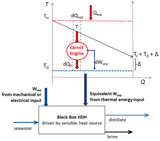
Figure 1. Black Box HDH control volume receiving the work of separation and the heat of separation from a variable temperature heat source.
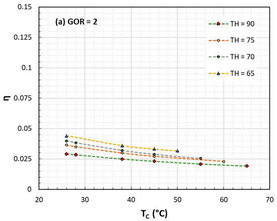
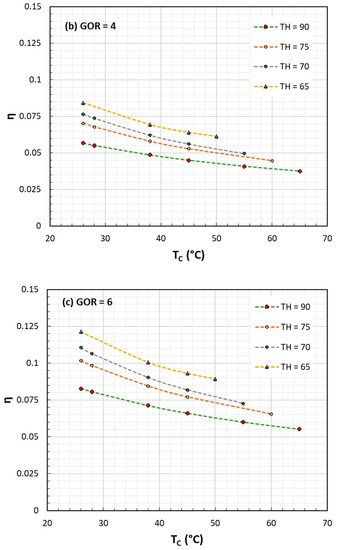
Figure 2. Exergy or II Law efficiency for HDH processes against TC at various TH and GOR: (a) GOR = 2; (b) GOR = 4; (c) GOR = 6. In all cases TH ranges from 65 to 90 °C.
3. Advanced Heat and Mass Transfer Techniques
Since its first design in the early 1960s, several modifications of the conventional HDH process have been introduced to improve the heat and mass transport phenomena. In HDH systems the energy footprint (main voice of the operating costs) and the size of equipment (proportional to the investment costs) represent a clear trade-off: the lower the driving force and the entropy generation, the lower the energy consumption but the higher the heat and mass transfer areas, and thus the equipment costs. The conventional configuration includes a direct contact humidification in a packed bed and a dehumidification via the surface of a heat exchanger with seawater flowing inside finned tubes. In addition to the classic fouling problems (mitigated by low temperatures), these heat exchangers suffer from the prevailing presence of non-condensable gas compared to water vapor. This aspect makes the heat and mass transfer a limiting factor in the design of HDH systems.3.1. Humidifier
The humidifier typically comprises a packed bed structure. Water is introduced through spraying at the upper section of the packing, while air is introduced in countercurrent from the bottom section of the bed. The analysis of this constituent can be accomplished using conventional methodologies originally developed for cooling towers [11,35,36][11][29][30]. While various types of packing materials can be used, it is commonly an economical polymeric material with an ample open area to minimize air pressure drop while offering a mass-transfer surface area for conducive evaporation. A notable advantage of the packed bed humidifier lies in its immunity to surface scaling or fouling, which would otherwise hinder the heat and mass exchange at the air–water interface. Furthermore, owing to its operation at atmospheric pressure and moderate temperatures, it is feasible to employ cost-effective structural materials, eliminating the need for expensive, corrosion-resistant metals. The abovementioned humidification columns have been widely investigated from the point of view of heat and mass transfer in process engineering, especially in relation to cooling towers operating at atmospheric pressure, where the packing heights are in the order of a few meters [35][29]. Along the axis of a packed bed, there two heat transfer mechanisms occurring simultaneously:-
a latent heat transfer mechanism supported by the transfer of mass in a stagnant medium (the inert air taking up the water vapor)
-
a sensible heat transfer mechanism between the gas and liquid phases (the flow direction depends on the temperature of the two phases)
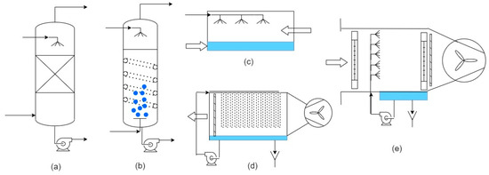
Figure 4. Equipment for heat and mass transfer in humidifiers: (a) Packed bed; (b) Bubble column; (c) Direct contact cross-current evaporator; (d) Cross-current evaporator with hollow fiber membrane contactor (HFMC); (e) Spray chamber.
3.2. Dehumidifier
As the carrier gas is usually a non-condensable gas present in very high concentrations (60–95 mol%), a large additional resistance to heat transfer is present in dehumidifier columns. The convective heat transfer rate, defined in Equations (9) and (10), is limited by low values of the heat transfer coefficient h0 (in the range of 18–30 W m−2 K−1) because of the non-negligible transfer of sensible heat via gas cooling [39,52][33][46]. On the other hand, the portion of heat transferred by vaporization is controlled by the mass transfer rate.𝑞ℎ=ℎ𝐺(𝑇−𝑇𝑤𝑏)
𝑞𝜆=𝑘𝑌λ(𝑌𝑠−Y)
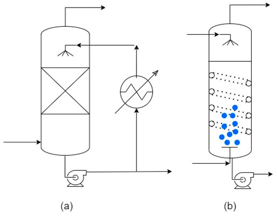
Figure 5. Equipment for heat and mass transfer in dehumidifiers: (a) Direct contact condenser (in spray chamber); (b) Direct contact condenser in bubble column (with coil).
References
- Kuzma, S.; Bierkens, M.F.P.; Lakshman, S.; Luo, T.; Saccoccia, L.; Sutanudjaja, E.H.; Van Beek, R. Aqueduct 4.0: Updated Decision-Relevant Global Water Risk Indicators; Technical Note; World Resources Institute: Washington, DC, USA, 2023.
- MacAlister, C.; Baggio, G.; Perera, D.; Qadir, M.; Taing, L.; Smakhtin, V. Global Water Security 2023 Assessment; United Nations, University Institute for Water, Environment and Health: Hamilton, ON, Canada, 2023.
- Capocelli, M.; Prisciandaro, M.; Piemonte, V.; Barba, D. A technical-economical approach to promote the water treatment & reuse processes. J. Clean. Prod. 2019, 207, 85–96.
- Barba, D.; Capocelli, M. Process analysis of the novel Flash-ME desalination process driven by low-grade thermal energy. Chem. Eng. Res. Des. 2023, 189, 721–733.
- Abedi, M.; Tan, X.; Klausner, J.F.; Bénard, A. Solar desalination chimneys: Investigation on the feasibility of integrating solar chimneys with humidification–dehumidification systems. Renew. Energy 2023, 202, 88–102.
- Lacroix, C.; Perier-Muzet, M.; Stitou, D. Dynamic Modeling and Preliminary Performance Analysis of a New Solar Thermal Reverse Osmosis Desalination Process. Energies 2019, 12, 4015.
- Li, Y.; Chen, X.; Xu, Y.; Zhuo, Y.; Lu, G. Sustainable thermal-based desalination with low-cost energy resources and low-carbon footprints. Desalination 2021, 520, 115371.
- Luberti, M.; Gowans, R.; Finn, P.; Santori, G. An estimate of the ultralow waste heat available in the European Union. Energy 2022, 238, 121967.
- Müller-Holst, H. Solar thermal desalination using the Multiple Effect Humidifcation (MEH) method. In Solar Desalination for the 21st Century; NATO Security through Science Series; Springer: Dordrecht, The Netherlands, 2007; Chapter 15; pp. 215–225.
- Narayan, G.P.; Sharqawy, M.H.; Summers, E.K.; Lienhard, J.H.; Zubair, S.M.; Antar, M.A. The potential of solar-driven humidification-dehumidification desalination for small-scale decentralized water production. Renew. Sustain. Energy Rev. 2010, 14, 1187–1201.
- Mistry, K.H.; Mitsos, A.; Lienhard, J.H. Optimal operating conditions and configurations for humidification-dehumidification desalination cycles. Int. J. Therm. Sci. 2011, 50, 779–789.
- Rahimi-Ahar, Z.; Hatamipour, M.S.; Ahar, L.R. Air Humidification-Dehumidification Process for Desalination: A review. Prog. Energy Combust. Sci. 2020, 80, 100850.
- Dawood, M.M.K.; Amer, A.; Mansour, T.; Teamah, M.A.; Aref, A. A Review Study of Experimental and Theoretical Humidification Dehumidification Solar Desalination Technology. Comput. Water Energy Environ. Eng. 2020, 9, 48.
- Lienhard, J.H. Humidification-Dehumidification Desalination. In Desalination: Water from Water; Kucera, J., Ed.; Scrivener Publishing: Beverly, MA, USA, 2019; pp. 387–446.
- Essa, F.; Abdullah, A.; Omara, Z.; Kabeel, A.; El-Maghlany, W.M. On the different packing materials of humidification–dehumidification thermal desalination techniques—A review. J. Clean. Prod. 2020, 277, 123468.
- McGovern, R.K.; Thiel, G.P.; Narayan, G.P.; Zubair, S.M.; Lienhard, J.H. Performance limits of zero and single extraction humidification-dehumidification desalination systems. Appl. Energy 2013, 102, 1081–1090.
- Narayan, G.P.; Chehayeb, K.M.; McGovern, R.K.; Thiel, G.P.; Zubair, S.M. Thermodynamic balancing of the humidification dehumidification desalination system by mass extraction and injection. Int. J. Heat Mass Transf. 2013, 57, 756–770.
- Narayan, G.P.; Sharqawy, M.H.; Lienhard, J.H.; Lam, S.; John, M.S. Multistage Bubble Column Humidifer. U.S. Patent 9790102, 18 July 2017.
- Narayan, G.P.; Mistry, K.H.; Sharqawy, M.H.; Zubair, S.M.; Lienhard, J.H. Energy effectiveness of simultaneous heat and mass exchange devices. Front. Heat Mass Transf. 2010, 1, 023001.
- Garg, K.; Beniwal, R.; Das, S.K.; Tyagi, H. Experimental investigation of a low-cost humidification-dehumidification desalination cycle using packed-bed humidifier and finned-tube heat exchanger. Therm. Sci. Eng. Prog. 2023, 41, 101858.
- Capocelli, M.; Moliterni, E.; Piemonte, V.; De Falco, M. Reuse of waste geothermal brine: Process, thermodynamic and economic analysis. Water 2020, 12, 316.
- Narayan, G.P.; Lienhard, J.H.; Zubair, S.M. Entropy generation minimization of combined heat and mass transfer devices. Int. J. Therm. Sci. 2010, 49, 2057–2066.
- Narayan, G.P.; Lienhard, J.H.; Zubair, S.M. Generalized Least Energy of Separation for Desalination and Other Chemical Separation Processes. Entropy 2013, 15, 2046–2080.
- Capocelli, M.; Balsamo, M.; Lancia, A.; Barba, D. Process analysis of a novel humidification-dehumidification-adsorption (HDHA) desalination method. Desalination 2018, 429, 155–166.
- Capocelli, M.; Balsamo, M.; Mazzeo, L.; Luberti, M. Thermodynamic analysis of the humidification-dehumidification-adsorption (HDHA) desalination process. Desalination 2023, 554, 116510.
- Ng, K.C.; Shahzad, M.W.; Son, H.S.; Hamed, O.A. An exergy approach to efficiency evaluation of desalination. Appl. Phys. Lett. 2017, 110, 184101.
- Shahzad, M.W.; Burhan, M.; Son, H.S.; Oh, S.J.; Ng, K.C. Desalination processes evaluation at common platform: A universal performance ratio (UPR) method. Appl. Therm. Eng. 2018, 134, 62–67.
- Shahzad, M.W.; Ng, K.C.; Burhan, M.; Chen, Q.; Jamil, M.A.; Imtiaz, N.; Bin Xu, B. Demystifying integrated power and desalination processes evaluation based on standard primary energy approach. Therm. Sci. Eng. Prog. 2022, 27, 101153.
- Treybal, R.E. Mass-Transfer Operations; McGraw-Hill Education: Dubuque, IA, USA, 1980.
- Kloppers, J.; Kröger, D. A critical investigation into the heat and mass transfer analysis of counterflow wet-cooling towers. Int. J. Heat Mass Transf. 2005, 48, 765–777.
- Nevarez, V. Extraction Based Thermodynamic Balancing for a Humidification Dehumidification Desalination Plant. Ph.D. Thesis, Massachusetts Institute of Technology, Cambridge, MA, USA, 2012.
- Narayan, G.P.; Thiel, G.P.; McGovern, R.K.; Lienhard, J.H.; Sharqawy, M.H. Humidifcation-Dehumidifcation System Including Bubble Column Vapor Mixture Condenser. U.S. Patent 8778065, 25 June 2014.
- Nawayseh, N.K.; Farid, M.M.; Al-Hallaj, S.; Al-Timimi, A.R. Solar desalination based on humidification process—I. Evaluating the heat and mass transfer coefficients. Energy Convers. Manag. 1999, 40, 1423–1439.
- Zhao, Y.; Zheng, H.; Liang, S.; Zhang, N.; Ma, X.L. Experimental research on four-stage cross flow humidification dehumidification (HDH) solar desalination system with direct contact dehumidifiers. Desalination 2019, 467, 147–157.
- Ghazouani, N.; El-Bary, A.A.; Hassan, G.E.; Becheikh, N.; Bawadekji, A.; Elewa, M.M. Solar Desalination by Humidification–Dehumidification: A Review. Water 2022, 14, 3424.
- Li, G.; Wang, J.; Zhang, F.; Liu, J. Comprehensive operational parameter analysis of cross-flow hollow fiber membrane humidifier for humidification dehumidification desalination. Desalination 2022, 542, 116066.
- Zeng, Z.; Sadeghpour, A.; Ju, Y.S. A highly effective multi-string humidifier with a low gas stream pressure drop for desalination. Desalination 2019, 449, 92–100.
- Li, G.-P.; Zhang, L.-Z. Laminar flow and conjugate heat and mass transfer in a hollow fiber membrane bundle used for seawater desalination. Int. J. Heat Mass Transf. 2017, 111, 123–137.
- Tariq, R.; Sheikh, N.A.; Xamán, J.; Bassam, A. An innovative air saturator for humidification-dehumidification desalination application. Appl. Energy 2018, 228, 789–807.
- El-Agouz, S.A.; Abugderah, M. Experimental analysis of humidification process by air passing through seawater. Energy Convers. Manag. 2008, 49, 3698–3703.
- El-Agouz, S.A. Desalination based on humidification–dehumidification by air bubbles passing through brackish water. Chem. Eng. J. 2010, 165, 413–419.
- Abd-ur-Rehman, M.; Al-Sulaiman, F.A. A novel design of a multistage stepped bubble column humidifier for the humidification of air. Appl. Therm. Eng. 2017, 120, 530–536.
- Shehata, A.; Kabeel, A.L.; Dawood, M.M.K.; Abdalla, A.M. Achievement of humidification and dehumidification desalination system by utilizing a hot water sprayer and ultrasound waves techniques. Energy Convers. Manag. 2019, 201, 112142.
- Easa, A.S.; Mohamed, S.M.; Barakat, W.S.; Habba, M.I.A.; Kandel, M.G.; Khalaf-Allah, R.A. Water production from a solar desalination system utilizing a high-speed rotary humidifier. Appl. Therm. Eng. 2023, 224, 120150.
- RKhalaf-Allah, A.; Abdelaziz, G.B.; Kandel, M.G.; Easa, A.S. Development of a centrifugal sprayer-based solar HDH desalination unit with a variety of sprinkler rotational speeds and droplet slot distributions. Renew. Energy 2022, 190, 1041–1054.
- Tow, E.W.; Lienhard, J.H. Experiments and modeling of bubble column dehumidifier performance. Int. J. Therm. Sci. 2014, 80, 65–75.
- Tow, E.W.; Lienhard, J.H. Analytical modeling of a bubble column dehumidifer. In Proceedings of the ASME 2013 Summer Heat Transfer Conference, Minneapolis, MN, USA, 14–19 July 2013. Paper No. HT2013-17763.
- Tow, E.W.; Lienhard, J.H. Heat flux and effectiveness in bubble column dehumidifers for HDH desalination. In Proceedings of the IDA World Congress on Desalination and Water Reuse, Tianjin, China, 20–25 October 2013.
- Narayan, G.P.; Sharqawy, M.H.; Lam, S.; Das, S.K.; Lienhard, J.H. Bubble Columns for Condensation at High Concentrations of Noncondensable Gas: Heat-Transfer Model and Experiments. AIChE J. 2013, 59, 1780–1790.
- Sharqawy, M.H.; Liu, H. The effect of pressure on the performance of bubble column dehumidifier. Int. J. Heat Mass Transf. 2015, 87, 212–221.
- Huang, J.H. Design of a Mobile Community Level Water Treatment System Based on Humidification Dehumidification Desalination. Bachelor’ s Thesis, Massachusetts Institute of Technology, Cambridge, MA, USA, 2012.
- Lam, S. Development of a Multi-Stage Bubble Column Dehumidifier for Application in a humidification Dehumidification Desalination System. Bachelor’ s Thesis, Massachusetts Institute of Technology, Cambridge, MA, USA, 2012.
- Eslamimanesh, A.; Hatamipour, M.S. Mathematical modelling of a direct contact humidification–dehumidification desalination process. Desalination 2009, 237, 296–304.
- Hu, T.; Hassabou, A.H.; Spinnler, M.; Polifke, W. Performance analysis and optimization of direct contact condensation in a PCM fixed bed regenerator. Desalination 2011, 280, 232–243.
- Wang, K.; Hu, T.; Hassabou, A.H.; Spinnler, M.; Polifke, W. Analyzing and modeling the dynamic thermal behaviors of direct contact condensers packed with PCM spheres. Contin. Mech. Thermodyn. 2013, 25, 23–41.
- Niroomand, N.; Zamen, M.; Amidpour, M. Theoretical investigation of using a direct contact dehumidifier in humidification–dehumidification desalination unit based on an open-air cycle. Desalination Water Treat. 2014, 54, 305–315.
- Agboola, O.P.; Egelioglu, F. An empirical evaluation of an integrated inclined solar water desalination system with spray jets variation. Desalination Water Treat. 2013, 53, 2875–2881.
- Okati, V.; Farsad, S.; Behzadmehr, A. Numerical analysis of an integrated desalination unit using humidification- dehumidification and subsurface condensation processes. Desalination 2018, 433, 172–185.
- Okati, V.; Behzadmehr, A.; Farsad, S. Analysis of a solar desalinator (humidification-dehumidification cycle) including a compound system consisting of a solar humidifier and subsurface condenser using DoE. Desalination 2016, 397, 9–21.
- Al-Sahali, M.; Ettouney, H.M. Humidification dehumidification desalination process: Design and performance evaluation. Chem. Eng. J. 2008, 143, 257–264.
- Narayan, G.P.; McGovern, R.H.; Lienhard, J.H.; Zubair, S.M. Helium as a Carrier Gas in Humidification Dehumidification Desalination Systems. In Proceedings of the ASME 2011 International Mechanical Engineering Congress & Exposition, Denver, CO, USA, 11–17 November 2011. IMECE2011-62875.
- Mousa, K.; Arabi, A.; Reddy, K.V. Performance evaluation of desalination processes based on the humidification/dehumidification cycle with different carrier gases. Desalination 2003, 156, 281–293.
- Ettouney, H. Design and analysis of humidification dehumidification desalination process. Desalination 2005, 183, 341–352.
More