Your browser does not fully support modern features. Please upgrade for a smoother experience.
Please note this is a comparison between Version 1 by Ryszard Dindorf and Version 2 by Sirius Huang.
Electric motors used in industrial machines and devices, as well as internal combustion engines (ICE) used in vehicles, mobile machines, and marine devices, participate in the transformation of mechanical power into hydraulic power. In power transmission, hydraulic drive systems have a high power density. Hydraulic pumps, as energy sources in hydraulic drive systems, are widely used due to their high working pressure and high flow rate. The hydraulic accumulator (HA) is a device that is used to store energy in the hydraulic system in the form of pressure energy.
- hydro-pneumatic accumulators
- hydraulic systems
- energy efficiency
1. Introduction
The hydraulic accumulator (HA) is a device that is used to store energy in the hydraulic system in the form of pressure energy. There are different types of HA that have specific tasks in hydraulic systems. HA is used primarily for the following purposes.
-
Energy storage and auxiliary power supply.HA is used as a secondary energy source during high fluid flow demand requirements.
-
Power source in dual pressure circuits.HA can provide a higher flow rate for a high-hydraulic circuit.
-
Emergency power source.HA can perform the necessary functions of the hydraulic system in the event of a loss of pump power and electric motor.
-
Equalisation of fluid flow.HA can equalise the difference in fluid volume in a closed hydraulic system.
-
Leak compensation.HA can replenish fluid in the hydraulic circuit when there is a leak.
-
Thermal expansion compensation.HA can protect the hydraulic system from pressure changes resulting from fluid expansion under high heat conditions.
-
Pulsation damping and hydraulic cushioning.HA can dampen pressure pulsations resulting from the effects of pump ripple and water hammer in hydraulic lines.
-
Pressure holding.HA holds pressure in a hydraulic circuit at the same level for a long time when all valves are closed.
In the HA, a balance is maintained between the pressure of the hydraulic fluid and the back pressure generated by the weight (weighted-loaded accumulator), the spring (spring-loaded accumulator), or the charged gas (gas-charged accumulator).
2. Gas-Charged Accumulators
The gas-charged accumulator, called the hydro-pneumatic accumulator (HPA), is often also referred to as a gas-spring accumulator. In an HPA, the gas used is incombustible, usually nitrogen (N2). The HPA contains an oil and gas chamber separated by gas-tight partitions. HPAs as pressurised devices are classified according to the separating elements, such as piston accumulators, bladder accumulators, and diaphragm (membrane) accumulators. Figure 1 shows diagrams of the type of HPA, piston, bladder, and diaphragm.
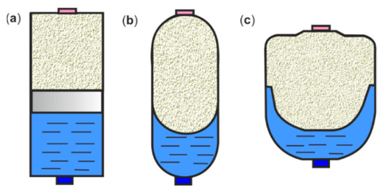
Figure 1.
HPA diagrams: (
a
) piston, (
b
) bladder, and (
c
) diaphragm.
In HPAs, there is a balance between the pressure of the hydraulic oil and the counter pressure generated by the gas. The HPA oil chamber is connected to the hydraulic circuit, which is filled with oil under increasing pressure, while simultaneously pressing the separating element compresses the gas. With a decrease in hydraulic pressure, the compressed gas expands, pushing the accumulated oil into the hydraulic system. To ensure safe operation of the HPA as a pressure device, a shut-off block is used. Safety and shut-off blocks are elements of hydraulic equipment that are used to protect overpressure on the fluid side and isolate and relieve the hydraulic accumulator. The safety and shut-off blocks of the accumulator take into account the applicable safety regulations according to the ISO standard [1][29]. Safety shut-off blocks are classified according to the Pressure Equipment Directive 2014/68/EU Article 4 [2][30]. The basic type of safety and shut-off block has a manually operated pressure release valve and a direct-acting pressure relief valve. Another type of safety and shut-off block has a solenoid-operated two-way directional valve for the automatic pressure release of the accumulator and hydraulic system [3][31].
The wide range of HPA applications require them to meet rigorous requirements for high-pressure operating, long power-on and power-off phases, and prolonged use. HPAs are an important component of various hydraulic power systems in many application areas, such as:
- ―
-
Hydraulic supply systems—hydraulic supply with energy storage capacity, pulsation damping, and smoothing of a pulsating flow.
- ―
-
Hydraulic transmission system—recovery and regeneration (recuperation) energy, regenerative suspensions, wave energy converters.
- ―
-
Suspension systems—hydro-pneumatic chassis systems for energy storage, pulsation suppression, and anti-roll stabilisation.
- ―
-
Automotive—hydraulic hybrid drivetrain.
- ―
-
Energy—hydraulic braking systems in wind turbines and energy reduction in photovoltaic installations.
- ―
-
Oil and gas—hydraulic emergency safety features used on drilling rigs.
For the specific application of HPAs, it is necessary to consider the advantages and disadvantages of different types of accumulators.
Advantages of the piston-type accumulator: long life, simple structure, large usable volume, withstands high pressures and temperatures, withstands large pressure fluctuations, convenient installation and filling, easy maintenance, suitable for grouping to increase the effective volume. Disadvantages of the piston type accumulator: high piston inertia, slow dynamic response, work hysteresis, leaks easily, heavy, expensive, and requires checking, replacement, and maintenance of the seal. The moving piston of the HPA is difficult to seal, which affects the service life of the accumulator. There is also a significant risk that gas enters the hydraulic circuit, which can result in unforced vibrations. The repair and maintenance of an HPA is not easy, as it involves the need for a specialised service.
Advantages of a bladder-type accumulator: compact and lightweight, the gas bag is made of a flexible material like rubber, the gas bag responds to changes in compression and expansion, and it has few functional parts, which makes it cheap. Disadvantages of the bladder type accumulator: the oil pressure at the outlet is not constant, the expansion of the gas bag causes the oil pressure to decrease, the volume of oil accumulating in the accumulator is small, the gas bag must be replaced after a period of operation, and the high oil temperature adversely affects the operation of the accumulator.
Advantages of the diaphragm-type accumulator: compact and lightweight, with no mechanical moving parts, responds quickly to even small changes in pressure, high working pressure, and the diaphragm provides a good seal between the gas chamber and the oil chamber. Disadvantages of the diaphragm type accumulator: the pressure exerted on the fluid is not constant and decreases as the diaphragm expands, it has a small usable volume, the diaphragm needs to be replaced after some time, and it cannot handle high-temperature fluid.
3. Basic Hydraulic Circuits with HPA
The main task of using HPA in hydraulic systems is to save energy. In hydraulic systems where there is a high-power demand in a short time, an economical solution is achieved using HPAs. Accuracy and precision of operation are required in modern hydraulically driven machines, which are exposed to vibrations and pressure shocks. The use of HPAs makes it possible to suppress pulsations and pressure spikes, reduce noise levels, and extend the life of the machines. Basic applications of HPAs in hydraulic systems are available in catalogues of hydraulic accumulator manufacturers [4][5][6][7][8][9][10][32,33,34,35,36,37,38], specialist books [11][12][39,40], and academic books [13][14][41,42].
Figure 2 shows the hydraulic circuit for the different oil requirements of the cylinder and motor. The HPA, as well as a hydraulic fluid (oil) reservoir, provides an increase in the fluid requirement for one hydraulic actuator, a cylinder, or a motor. During breaks in the work of the hydraulic cylinder and hydraulic motor, the HPA is recharged. Due to the use of HPA, it is possible to install pumps with less power, which reduces hydraulic and heat losses, and then the cooler may be redundant.
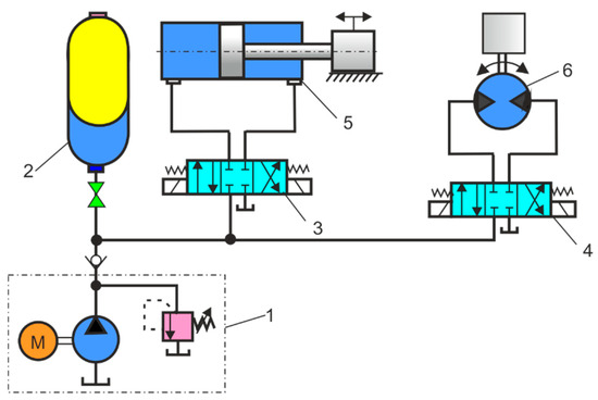
Figure 2. Hydraulic circuit diagram: 1—hydraulic power unit, 2—HPA, 3—directional control valve, 4—directional control valve, 5—cylinder, 6—hydraulic motor.
Figure 3 shows the hydraulic circuit for the short-time oil demand in the cylinder in an injection moulding. HPA as a hydraulic fluid store ensures that large fluid needs are in demand in a short time. In die-casting machines, injection-moulding machines, and plastic-blowing machines, large amounts of oil in the cylinders are required in a short time during the injection phase. In most cases, such shutdown systems require minimal oil during normal operation.
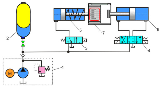
Figure 3. Hydraulic circuit diagram: 1—hydraulic power unit, 2—HPA, 3—directional control valve, 4—directional control valve, 5—long stroke cylinder, 6—short stroke cylinder, 7—injection moulding machine.
Figure 4 shows the hydraulic circuit for maintaining pressure in the cylinder to clamp the roller for a long time. Once the clamp pressure is reached, the hydraulic pump can be idled or used for other applications. The HPA maintains the required holding pressure throughout the process.
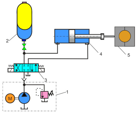
Figure 4.
Hydraulic circuit diagram: 1—hydraulic power unit, 2—HPA, 3—directional control valve, 4—cylinder, 5—clamping device.
Figure 5 shows a hydraulic circuit where an HPA is used as a safety device in the event of a hydraulic pump or directional control valve failure. In this system, the on/off safety valve is connected to the bypass of the directional control valve, and the HPA in these applications is normally inactive.
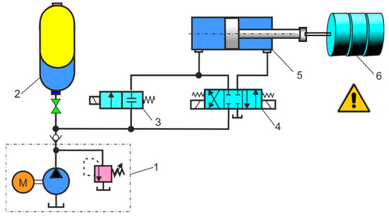
Figure 5. Hydraulic circuit diagram: 1—hydraulic power unit, 2—HPA, 3—on/off safety valve, 4—directional control valve, 5—cylinder, 6—feed device.
Figure 6a shows a hydraulic circuit where the HPA is used as an emergency stop device in the clutch and hydraulic brake unit. Therefore, the hydraulic energy needed is constantly available in the HPA to perform an emergency stop. HPA can be used, for example, to control the emergency brakes, funicular rail, or gondola doors. Figure 6b shows a hydraulic circuit where the HPA is used as an emergency stop device in the inverted clutch and the mechanical brake unit. This type of system is often recommended when braking is performed with a spring mechanical brake and the HPA and cylinder operate the clutch clamp. In the event of a directional control valve failure, the emergency on/off valve will work.
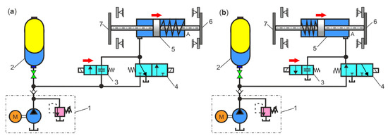
Figure 6. Hydraulic circuit diagram: (a) hydraulic brake unit: 1—hydraulic power unit, 2—HPA, 3—on-off safety valve, 4—directional control valve, 5—cylinder, 6—clutch, 7—hydraulic brake; (b) mechanical brake unit: 1—hydraulic power unit, 2—HPA, 3—on-off emergency valve, 4—directional control valve, 5—cylinder, 6—clutch, 7—mechanical brake.
Figure 7a shows a hydraulic circuit with HPA as a leak compensator that compensates for oil loss due to internal or external leaks over an extended period of time when the cylinder is pressurised but not operating. An oil leak causes a pressure drop in the hydraulic circuit, which is limited by the pressure switch. Figure 7b shows a hydraulic circuit with HPA as a thermal expansion compensator, which is especially effective when heat causes the volume of fluid in the system to expand. Changes in the volume of a liquid resulting from changes in temperature within a closed circuit cause an increase in pressure. HPA can be used to relieve such pressure fluctuations. The increase in pressure in the hydraulic circuit is limited by the pressure switch.
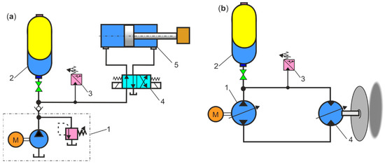
Figure 7. Hydraulic circuit diagram: (a) HPA as leak compensator: 1—hydraulic power unit, 2—HPA, 3—pressure switch, 4—4/2 directional control valve, 5—cylinder; (b) HPA as thermal expansion compensator: 1—pump, 2—HPA, 3—pressure switch, 4—hydraulic motor.
Figure 8a shows a hydraulic circuit with an HPA as a hydraulic shock absorber (water hammer absorber), which is installed near the rapidly closed shut-off valve. When rapidly closing, a valve creates a compression wave. This compression wave travels at the speed of sound to the end of the pipe and back again to the closed valve, causing an increase in pressure. The resulting rapid pressure pulsations or high-pressure surges may cause damage to the components of the hydraulic system. One of the important applications of HPAs is the elimination of hydraulic shocks. Figure 8b shows a hydraulic circuit with an HPA as a pressure pulsation damper, which is installed near the pump or actuators (cylinders, motors) as a pulsation generator. In many hydraulic systems, pressure pulsations and fluctuations can cause damage, decrease efficiency, and even cause safety risks. HPAs can effectively damp the pressure pulsation and ensure the smooth and safe operation of the hydraulic system. The bladder-type HPA is adapted to absorb shock pressure and eliminate pressure pulsations.
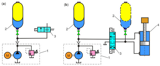
Figure 8. Hydraulic circuit diagram: (a) HPA as hydraulic shock absorber: 1—hydraulic power unit, 2—HPA, 3—shut-off valve; (b) HPA as pressure pulsation damper: 1—hydraulic power unit, 2—HPA, 3—4/3 directional control valve, 4—cylinder.
-
Notes on future and frontier research methods
As can be seen from the presented diagrams, HPAs can be used in various applications in the industry. Researchers should design novel types of HPAs with an improved performance in specific application areas. Significant pressure drops occur during HPA charging and discharging, especially in small, variable-frequency hydraulic systems. For this reason, a new type of HPA should be designed with a mechanism to compensate for the nonlinear relationship between gas pressure and volume.
4. Hydraulic System with Energy Regeneration
Hydraulic transmission systems with HPAs are widely used in various industries, construction machinery, hydraulic vehicles, regenerative suspensions, and wave energy converters [15][43]. The recovering and regeneration (recuperation) of energy, called regenerative braking, is the most important feature of hydrostatic propulsion systems. Energy regeneration is required in modern energy-saving hydraulic machines. In hydraulic systems, the regenerative energy is the static energy that returns to the HPA when the hydraulic motor is slowed or its load drops. Energy storage in HPAs is only viable when the propulsion system is cyclically operated at high efficiency. The efficiency of energy recovery, according to the efficiency values given for the hydraulic system, is 69% [16][44]. The energy stored in the HPA is used to accelerate the propulsion system. Examples of general hydraulic propulsion with regenerative braking and energy storage in open-loop and closed-loop systems with HPA are shown in Figure 9. In regenerative hydraulic propulsion systems, a pump is used as the primary energy source, an accumulator as the secondary energy source, and a reversible drive unit with secondary control, which, depending on the direction of energy transmission, works as a motor or pump. In such systems, a two-way flow of energy is possible. In one direction, energy is transferred from the pump and accumulator to the motor/pump. Conversely, the energy recovered from braking (regenerative braking) is transferred from the motor/pump to the hydraulic accumulator, where the potential energy can be stored.
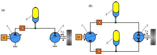
Figure 9. General hydraulic propulsion with energy regeneration: (a) open-loop system; (b) closed-loop system: 1—hydraulic pump, 2—HPA, 3—hydraulic motor/pump.
Energy-regeneration systems are a key factor in improving energy efficiency in hydraulic machinery. In [17][45], an energy regenerative system was proposed for an accumulator-powered hydraulic impulse test device. Mathematical analysis and simulations show that a hydraulic system in the impulse testing system with an accumulator can reduce the energy consumption by 15% over the system without an accumulator in the cycle, while the energy efficiency of the hydraulic impulse testing system increases from 62.82 to 75.71% due to the use of accumulator. In [18][46], the purpose of the research was to increase the efficiency of the hydraulic system by introducing the concept of a regenerative system. The regenerative circuit is used to accelerate the extension stroke of a single rod, double-acting, hydraulic cylinder. In [19][47], to reduce energy losses in the relief valve, a hydraulic energy regeneration unit (HERU) was connected to the outlet of this valve, which reduces the pressure drop between the inlet and the outlet of the relief valve. Experimental results show that a relief valve with HERU connected to its outlet can achieve better pressure regulation properties. The energy recovery efficiency saved by HPAs is up to 83.6%, with a higher HPA pre-charge. The design of the HERU bleed valve has been proposed to allow a better performance and higher efficiency in the hydraulic system. The article [20][48] deals with the design of an experimental rig with the hydromechanical system and energy regeneration. The proposed experimental rig is a scaled simulator of a heavy-vehicle hydrostatic driveline. In [21][49], a novel energy-saving hydraulic system based on a hydrostatic system and an HPA was proposed. A hydraulic system efficiency model was developed and used to estimate the energy utilisation and recovery of the system under different conditions. A model validation indicated that the energy recovery potential of the system ranged from 32% to 66% depending on the pump/motor displacement. In this paper [22][50], electric and hydraulic regeneration methods are studied to recover potential energy from an electro-hydraulic forklift truck. In the hydraulic regeneration system, the hydraulically operated forklift is equipped with an energy recovery system consisting of pressure accumulators to store energy and a hydraulic digital valve package for precise leakage-free flow control.
In [23][51], various energy storages based on a Sun-Cycle LiFePO4 type battery, Maxwell Technologies BCAP0050 P270 S01 type ultracapacitors, and Parker Hannifin A2N0058D1K type HPA were compared. Both the ultracapacitor and HPA are designed to have the same energy storage capacity. Charge and discharge tests of energy storages were carried out to compare their power density, energy density, cost, and efficiency. The tests showed that the power density in the HPA was 21.7% higher compared to the ultracapacitors. Moreover, the cost/power ratio in the hydraulic accumulator was 2.9 times smaller than the ultracapacitors. Under the conditions tested, the overall energy efficiency of the HPA was 87.7%, and the overall energy efficiency of the ultracapacitor was 78.7%. The parameters of the three energy storages tested are compared and summarised in Table 1. Table 2 compares the energy densities, and Table 3 compares the power densities of the three energy storages tested: battery, ultracapacitor, and HPA.
Table 1.
The parameters of different energy storages compared.
| Battery | Ultracapacitor | HPA |
|---|
| Energy Storage | Energy/Volume Wh/m |
|---|
Table 3.
Comparison of the power density of different energy storages.
| Energy Storage | 3 | Power/Volume kW/mEnergy/Mass Wh/kg |
Cost/Energy EUR/Wh |
|
|---|---|---|---|---|
| 3 | Power/Mass | kW/kg |
Cost/Power EUR/kW |
|
| Mass 9.8 kg | Mass 12.2 g | Mass 4.53 kg | ||
| Battery | 195,144 | 115.2 | 0.42 | Energy capacity 1127 Wh |
| Ultracapacitor | ||||
| Battery | 325.24 | 0.192 | 252 | |
]. In [28][56], the latest technological advances and breakthroughs in mechanical–electric–hydraulic hybrid energy storage systems in vehicles are analysed and discussed in detail, which are divided into four categories: passenger cars, minibuses and buses, commercial vehicles, and special vehicles.
Figure 10 shows the basic structures of hydraulic hybrid drives (HHD), such as parallel hydraulic hybrid (PHH), series hydraulic hybrid (SHH), and series parallel hydraulic hybrid (SPHH) [29][57]. In the PHH, the internal combustion engine (ICE) is mechanically connected to the wheels of the vehicle. When high power is required, the internal combustion engine and the hydraulic motor can operate in parallel. During braking, the hydraulic motor operates like a hydraulic pump and transmits the recovered braking energy to the high pressure HPA. In the SHH, the ICE drives the hydraulic pump at optimum speed, which transfers the hydraulic energy to a hydraulic motor connected to the vehicle’s wheel drive differential, and excess energy is stored in the HPA. During braking, the hydraulic motor operates as a hydraulic pump and transfers the recovered energy to the high-pressure HPA. An SPHH has the advantages of both SHH and PHH types. These two types of drive provide a high performance throughout the vehicle speed range in different driving situations. The SPHH control system should ensure smooth mode switching during drives. However, the structure of the SPHH is complex and requires reliable drive operation.
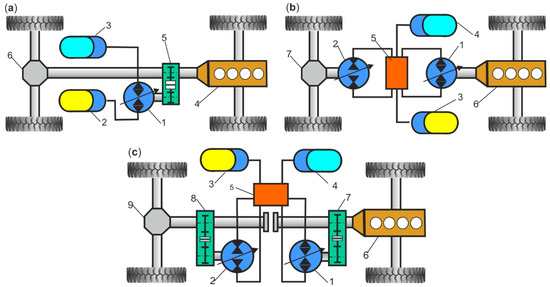
Figure 10. Basic structure of HHD. (a) PHH: 1—pump/motor unit, 2—high-pressure HPA, 3—low-pressure HPA, 4—ICE, 5—mechanical gear, 6—differential; (b) 1—pump/motor unit, 2—motor/pump unit, 3—high-pressure HPA, 4—low-pressure HPA, 5—valve block, 6—ICE, 7—differential; (c) SPHH: 1—pump/motor unit, 2—motor/pump unit, 3—high-pressure HPA, 4—low-pressure HPA, 5—valve block, 6—ICE, 7, 8—mechanical gears, 9—differential.
In [30][58], the focus was on thermodynamic effects and their influence on the energy savings potential of HHD by using endoreversible thermodynamics as an ideal modelling framework. In this case, the energy savings for accelerating the vehicle are expected to be around 10% and the reduction in the energy transferred to conventional disc brakes to be around 58%. In [31][59], factors that influence the speed of energy recovery in the braking system with energy recovery in a hybrid hydraulic vehicle (HHV) were studied. In [32][60], a novel energy recovery system was proposed for hybrid hydraulic excavators based on a digital pump with an energy recovery function. The simulation results showed that this hybrid system could decrease the system input energy by 78.1%.
In [33][61], different vehicle configurations were compared: a conventional internal combustion engine (ICE), series hybrid electric vehicle (SHEV), series hydraulic hybrid vehicle (SHHV), parallel hybrid electric vehicle (PHEV), parallel hydraulic hybrid vehicle (PHHV), electric vehicle (EV), and hydraulic-electric hybrid vehicle (HEHV). The results of the study show that the fuel consumption was 21.80% lower in the SHHV compared to the SHEV and the fuel consumption was 3.80% lower in the PHEV compared to the PHHV. Furthermore, the HEHV consumed 11.4% less electricity than the EV. Table 4 shows a comparison of the economic savings of various hybrid vehicle configurations in relation to the base ICE.
Table 4.
Economic savings of various vehicle configurations.
| Vehicle Configuration |
Improvement Economic Savings | Energy Consumption kW/km |
Energy Cost EUR/km |
||
|---|---|---|---|---|---|
| Energy capacity 1.82 Wh | |||||
| 2539.70 | Energy capacity 1.77 Wh | ||||
| 2.72 | 129 | ||||
| Ultracapacitor | 2588 | HPA | 1227 | 0.29 | 376 |
| 2.21 | ||||
| 202 | ||||
| Voltage 48 V | Voltage 2.7 V | |||
| HPA | 7548 | Volume capacity 950 cm3 | ||
| 2.69 | 70 | Current 60 A | Current 6.1 A | Pressure 207 bar |
Table 2.
Comparison of the energy density of different energy storages.
The higher energy efficiency in HPAs and the better power density compared with ultracapacitors could be determining factors in choosing a hydraulic system over an electric system for a specific application, where there is a need to rapidly charge or discharge energy storage devices, such as in the case of regenerative breaking.
-
Notes on future and frontier research methods
With the development of renewable energy research and energy-saving technologies, energy regeneration and conversion (ERC), energy storage technology (EST), and hydraulic transmission systems (HTS) should also be developed.
5. Hydraulic Hybrid System
Hybrid systems are generally classified on the basis of the configuration of the drivetrain and how they store energy. Originally, hydraulic hybrid technology was designed for military vehicles, trucks, vans, and buses. The concept of the Hydro-Bus was developed in Hanover in the early 1980s. For heavy municipal vehicles (garbage trucks), loading equipment and construction machines operating in short working cycles (with frequent stops), Bosch Rexroth has developed a parallel hybrid drive with hydrostatic regenerative braking (HRB—Hydrostatic Regenerative Braking System) [24][52]. The research also concerned hydraulic hybrid drives in such vehicles as SUVs: Hummer H3, Nissan Titan, Pathfinder, Dodge Durango. Ford Explorer, and GMC Yukon [25][53]. One of the first hydraulic parallel hybrid drives introduced to urban vehicles was the Parker Hannifin CBED (Cumulo Brake Energy Drive) system [26][54]. The latest solution to hybrid hydraulic drives was developed in cooperation between Bosch and Peugeot Citroën PSA [27][55
| ICE | Base data | 2568 | 0.075 |
| SHEV | 15.4% | 2174 | 0.064 |
| SHHV | 33.8% | 1700 | 0.045 |
| PHEV | 38.2% | 1586 | 0.046 |
| PHHV | 35.9% | 1646 | 0.044 |
| EV | 72.6% | 513 | 0.020 |
| HEHV | 75.7% | 455 | 0.018 |
Currently, the most important limitations related to the use of vehicles with a hydraulic hybrid drive are the noise, large size, and complexity of the structure. The latest generations of hydraulic motors that produce a high torque and at the same time maintain the small size of the device allow the use of these solutions in such utility vehicles as garbage trucks or city buses.
-
Notes on future and frontier research methods
Research into hybrid hydraulic drives should aim for smaller, lighter, and more efficient HPAs that can be used in both small consumer vehicles and large, heavy-duty, and commercial vehicles. For example, for a hydraulic hybrid drive system, a new HPA piston should be designed, in which the shell is made of carbon-fibre-reinforced plastic and the piston of aluminium. At the same time, the thermodynamic behaviour of the liquid and gas, as well as their interaction with carbon fibre, must be determined in detail. The implementation of HPAs from carbon fibre limits their use in high-pressure systems. The cost of using carbon fibre is still high.