Your browser does not fully support modern features. Please upgrade for a smoother experience.
Please note this is a comparison between Version 2 by Lindsay Dong and Version 1 by Ayah Marwan Rabi.
Liquid air energy storage (LAES) has gained prominence as an alternative to existing large-scale electrical energy storage solutions such as compressed air (CAES) and pumped hydro energy storage (PHES), especially in the context of medium-to-long-term storage. LAES offers a high volumetric energy density, surpassing the geographical constraints that hinder current mature energy storage technologies. The basic principle of LAES involves liquefying and storing air to be utilized later for electricity generation.
- LAES
- standalone LAES
- hybrid LAES
- thermodynamic
- LAES performance
1. Introduction
In recent years, there has been a significant increase in the utilization of renewable energy sources, specifically wind power and solar photovoltaic technology, driven by the goal of decarbonizing the energy sector. According to the International Energy Agency (IEA), renewable sources accounted for 29% of global electricity generation in 2020 [1]. Projections indicate that this percentage will rise to 49% by 2030 [1]. However, a key limitation of renewable energy sources is their intermittent nature, which hampers their ability to provide a consistent and stable power supply. This intermittency creates a mismatch between the energy generated and the demand on the grid. To address this challenge, energy storage systems have emerged as a viable solution [2,3,4][2][3][4]. Thermal energy storage technologies are currently available at various stages of development. In conventional large-scale energy storage applications, pumped hydro energy storage (PHES and CAES) and compressed air (CAES) are considered to be the most common technologies. These technologies are mature technology for large-scale and medium-to-long-term storage applications and are available on the commercial market at relatively low costs [4]. The low energy density of these systems and their geographical restrictions have prompted attention to modern technologies that have been developed to overcome these drawbacks [2]. Liquid air energy storage (LAES) systems are currently gaining increasing attention from academia and industry due to their advantages over alternative technologies designed for the purpose of large-scale energy storage [5]. LAES offers a range of notable benefits: firstly, it has the advantage of not being limited by geographical restrictions, unlike alternatives such as CAES and PHES, where large storage facilities typically require large natural storage capacity. Secondly, it relies on readily available, off-the-shelf components commonly employed in various industrial applications. Thirdly, it requires significantly less storage space compared to CAES, with a reduction of approximately 700 times [5,6,7,8][5][6][7][8]. The utilization of both hot and cold energy recovery cycles in the LAES system contributes to achieving a higher round-trip efficiency (RTE); the RTE is defined as the ratio between the heat input and the heat output during the charging and discharging processes [9]. Furthermore, locating LAES systems in proximity to other energy conversion processes can help alleviate the need for supplementary pipelines and the associated costs. Therefore, LAES demonstrates substantial promise as a viable option for large-scale applications [9].
2. LAES Basic Principles
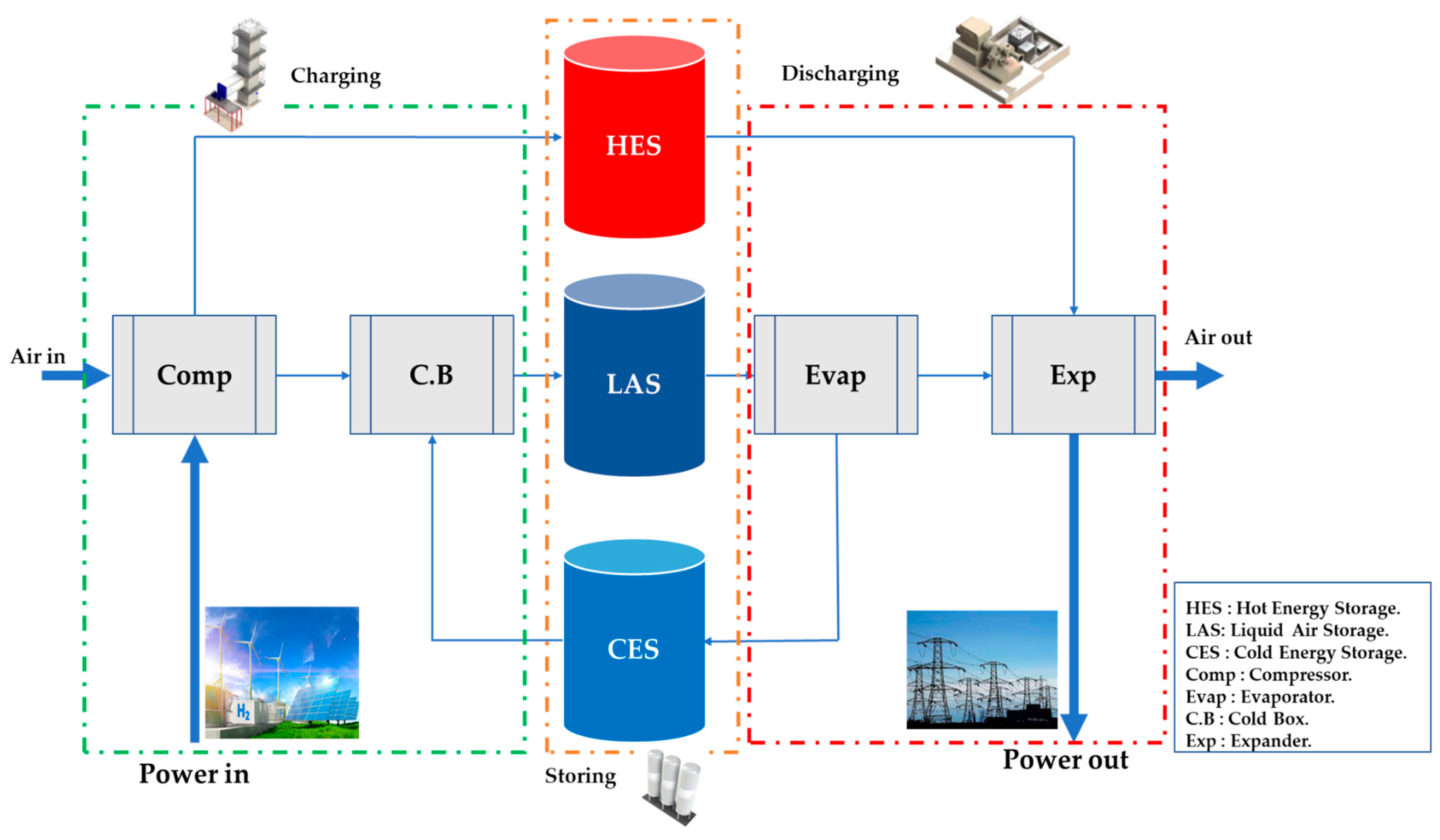
LAES is a technique used to store liquefied air in a large-scale system. Similar to CAES systems, LAES technology is charged using surplus grid electricity and discharged during periods of high electrical demand [10,11,12,13][10][11][12][13]. Through LAES, which acts as a buffer for the electrical system, the integrability and availability of various renewable energy sources can be improved. The LAES system consists of three main cycles: the charging cycle, the storing cycle, and the discharge cycle, as illustrated in Figure 1. The charging system (gas liquefaction process) consists of an air liquefier that uses excess electrical energy at off-peak times to draw air from the surroundings, and the air is cooled down to (−196 °C) during this stage to liquefy 700 liters of ambient air into 1 liter of liquid air. Atmospheric air is pressurized through the compressor using excess electricity. During the compression stage, the storage tank can be used to superheat the air in the discharging process to increase power output. A TES (thermal energy storage) material such as thermal oil, hot water, or glycol is typically used. In the storing cycle, liquefied air is stored at low pressure in an insulated tank, which functions as the energy store. A cold box is used to cool compressed air using come-around air, and a cold storage tank can be filled with liquid-phase materials such as propane and methanol, as well as solid-phase materials such as pebbles and rocks. During the discharge cycle, cold energy is recovered from liquid air storage. To recover the power, liquid air is pumped into the high-pressure evaporator and heated. During the evaporation stage, the high-grade cold exergy is recovered and stored in a cold storage tank, which can be reused in the cooling-down process, reducing power consumption at the charging system, where liquid air is produced through the expansion of air. The heat storage tank then heats the air, which is used to generate electricity through air turbines at high demand. An additional cycle can be added to improve the system efficiency and reduce the energy demand for producing liquid air, called cold recycle. In this stage, the cold gas is exhausted during the power recovery process and recycled back into the first stage (gas liquefaction process).Figure 1.
LAES has a number of benefits over competing solutions, including higher energy densities and no site restrictions, as previously mentioned. Due to the cryogenic temperatures of liquid air [11], a significant portion of heat sources available at ambient temperatures can be utilized to drive the power generation cycle. As a result, not only is combustion eliminated and carbon emissions reduced, but the LAES process is also able to recover low-temperature streams, such as waste heat. LAES can be integrated with external sources of heat and cold, resulting in synergies and symbioses with other processes, such as those occurring at nearby industrial sites.
LAES technology is categorized into two types: standalone LAES systems and hybrid LAES systems. Standalone systems only contain the basic LAES layouts. Only electricity is used as an energy source for input and output; air and heat carriers are the only fluids used in the LAES process. Hybrid systems incorporate external processes utilizing cold or hot thermal streams from external fluids. Hybrid systems can also incorporate external processes utilizing cold or hot thermal streams from external fluids. Energy can now be extracted from fuel in the form of electricity, chemical energy, cold, and heat.
3. LAES Performance Improvement Methods
3.1. System Configuration and Optimisation
To enhance the performance of the LAES system, significant efforts have been dedicated to improvement. A study conducted by Morgan et al. [26][14] explored performance enhancement by optimizing the gas liquefaction process using a conventional two-turbine Claude system operating in parallel (Figure 32). However, this cycle encountered a pinch in the cold box, which restricted the effective utilization of cold energy. To overcome this limitation, a three-turbine cycle was proposed as a replacement for the single cold turbine [6], resulting in an increase from 47% to 57% in round-trip efficiency.
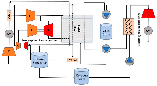
Figure 32. Schematic representation of the LAES with a two-turbine Claude cycle, adapted from [26].
A study conducted by Abdo et al. [27][15] compared three cryogenic energy storage cycles: Linde-Hampson, Claude, and Collins. All three cycles produced similar amounts of system power, but the Claude cycle had a superior cost-benefit ratio over the others. Guizzi et al. [28][16] examined using a LAES system that recirculates cold thermal energy from regasification and hot thermal energy from adiabatic compression. Their results led to a 54.4% RTE. Chino et al. [17] introduced a combustor combined with a LAES system. As a result of the combustion of oxygen, natural gas, and compressed air, the temperature of the compressed air at the gas turbine’s inlet is raised. When compared to conventional LAES with a combustor, it was found that the output power was much higher. In addition, they investigated the use of cold recovery in gas liquefaction and found that it had an RTE of 70%, higher than the 60% efficiency of LAES standalone.
Another approach to increase efficiency is to combine the conventional LAES cycle with other cycles. According to Antonelli et al. [29][18], integrating a conventional LAES cycle with an ORC (organic Rankine cycle) can result in a maximum RTE of 77%. To reduce the specific power consumption of the compressor, the authors developed another hybrid LAES system using an open Brayton cycle. A Brayton cycle is employed in this LAES to cool the working fluid to a low temperature through recuperation; the cooling energy from the evaporation of liquid air is used in this process. Such a hybrid system’s round-trip efficiency might reach a maximum of 90%, which makes this method highly desirable for enhancing LAES performance. Despite its advantages, the hybrid LAES has the same drawbacks as the external heat source in terms of higher CO2 emissions and operating costs. This makes combustion-free LAES the better option.
3.2. Thermal Energy Storage Enhancements
According to the definition of a LAES standalone system, the charge and discharge processes do not require the use of any external heating or cooling sources. Thermal energy storage is typically used by the standalone LAES to recover cold/heat from the expansion and compression processes. Compression heat can range from 150 °C to 300 °C or even higher depending on the compression ratio and the number of compression stages, while liquid air evaporation can produce cold energy as low as −150 °C.
TES technologies may play an important role in the efficient use of compression heat and expansion cold during the charging and discharging of the LAES process in order to overcome demand–supply mismatches [34][19]. Packed bed storage is a TES method and has attracted the most research; this serves as a direct contact heat exchanger and an energy storage device and is a very reliable and reasonably inexpensive procedure.
A packed bed was described [35,36][20][21] as a mathematical model based on assumptions of the gas-phase temperature and solid-phase temperature, and the model was used to investigate the effects of porosity, particle diameter, and inlet velocity. They found that increasing the porosity led to a quicker charge time but reserved the thermal storage capacity and charge efficiency. Reducing the particle diameter increased the charge efficiency without having any significant effect on the thermal storage capacity. The performance was found to be less sensitive to the inlet velocity, with an increase in the velocity reducing the charge efficiency.
A novel liquid air energy storage (LAES) system using packed beds for thermal storage was investigated and analyzed by Peng et al. [37][22]. A mathematical model was developed to explore the impact of various parameters on the performance of the system. According to the results, the LAES system could achieve a round-trip efficiency of 50% and 62% with an appropriate parametric design and existing technologies. The inlet temperature of cold boxes and the charge and discharge pressures had significant effects on both the temperature distribution inside the cold boxes and the overall round-trip efficiency. Increasing the inlet temperature of the cold box had a negative effect on system efficiency, while increasing the charge and discharge pressures had a positive impact.
3.3. Integration of LAES
Integrating LAES with external thermal sources can enhance its performance and make it a more versatile energy storage system. For instance, gas turbines can significantly increase their shaft work during discharging cycles by using a natural gas combustor [17,29,30][17][18][23]. As well as generating cold energy for pre-cooling compressed air to increase liquid air production, a refrigeration cycle can be used to cool compressed air at the compressors’ inlets to reduce the amount of specific power required. A geographically and mechanically combined LAES system interconnects the LAES with industrial systems, storing and releasing energy as needed. Industrial processes can provide the necessary heat or cold energy. As most thermal energy cannot be effectively employed in industrial operations, there are financial benefits for both the LAES operator and the industrial partners. Numerous approaches have been applied to integrate LAES with a variety of processes, including Liquified Natural Gas (LNG) regasification, wind power generation, nuclear power production, and solar power generation.4.4. Hot and Cold Thermal Recycle
3.4. Hot and Cold Thermal Recycle
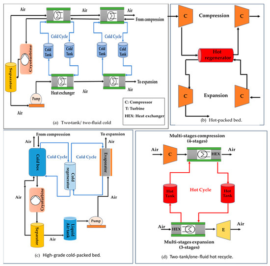
Hot and cold energy streams are produced at certain LAES charge and discharge stages and are required at other stages. In particular, the high-grade cold produced during air evaporation can be utilized to support air liquefaction, and reheating can utilise compression heat as a thermal reservoir at high temperatures. The performance of the plant depends on the efficient internal utilisation of such streams inside the LAES process, particularly when it comes to cold recycling. Compared to the loss of heat in the hot recycle, the losses of cold energy had a seven times greater influence on LAES efficiency [44][24]. Different configurations of TES, storage media, and Heat Transfer Fluids (HTF) have been used in a number of thermal recycling systems; the most common ones are shown in Figure 43 [8,13,46,47][8][13][25][26].Figure 43. Various types of thermal recycling systems: (a) two-tank/two fluids cold; (b) hot-packed bed; (c) high-grade cold-packed bed; (d) two-tank/one-fluid hot recycle, adapted from [8,13,46,47][8][13][25][26].
Compared to the initial proposal of reducing liquefaction work by pre-cooling the upstream compressed air, it is found that combining high-grade cold from liquid air evaporation with additional cooling in the cold box enhances LAES performance the most. Initially, solid regenerator-type storage systems were proposed for cold recycling since evaporation temperatures (∼90 K) require material durability at cryogenic conditions. One such system is a solid matrix made of 304 stainless steel [16][27], while another is a packed bed of rocks [6] and concrete pebbles inserted into steel pipes [17]. The capability of direct heat transfer is considered one of the most important features of regenerators, in addition to the availability of storage media, thermal stability, and low cost. Cryogenic packed beds have primarily been examined experimentally [48][28] or using dynamic numerical models [49][29]. The difficulties of extrapolating thermal properties in the cryogenic range, as well as their variation with temperature, make experimental results highly valuable in this context [49][29].
The literature has also suggested liquid TES solutions for cold recycling, for example, propane (R290) [28[16][30],54], methanol (R218), and methanol [28,33][16][31]. A variety of liquids are being proposed for cold storage at rising temperatures since no liquid is suitable in the range of (0 to −196 °C). Using vermiculite insulation in a small-scale test facility, a propane-R123 configuration presented 91% thermal efficiency but with higher thermal losses in comparison to solid-packed beds.
By utilizing the compression heat released during liquefaction, hot recycling is primarily responsible for raising the temperature of the turbine inlet. Not all rejected heat may be used in this situation, and an ambient heat exchanger is often rejected in a circuit. In this scenario, two tanks are usually used with liquid TES; however, a hot packed-bed TES has only been evaluated in one study, similar to the adiabatic CAES system [56][32]. It is also possible to use two different types of fluids (for example, oil and water) when the temperature rises [8]; this can produce a temperature glide that is better suited for coupling with external power cycles.
4.5. Summary of Approaches for LAES Enhancement
3.5. Summary of Approaches for LAES Enhancement
A range of approaches have been applied to improve the performance of LAES technologies. These include considering the TES media, as shown in Table 4, and considering enhanced energy storage, for example, the use of a packed bed [38][33] can increase the RTE to 60%. An improved RTE of 57% was found when multi-stage turbines were introduced [6], and studies involving heat/cold recovery achieved an RTE of up to 70% [17]. Further enhancements involved combining with other cycles, such as the ORC or Brayton, giving an improved RTE of 77% [29][18], combining with combustion [29][18], or integrating with an external source such as an NPP [4] or LNG regeneration [41][34] which have been shown to give an RTE of 76%, 70%, and 70%, respectively. These features can also be combined to give a further improvement; for example, combining an additional Brayton cycle with an integrated combustion process [13] gave an RTE of almost 130%.
References
- IEA. Renewables–Global Energy Review 2021–Analysis-IEA. Global Energy Review 2021. 2021. Available online: https://www.iea.org/reports/global-energy-review-2021/renewables (accessed on 11 May 2023).
- Rabi, A.M.; Radulovic, J.; Buick, J.M. Comprehensive Review of Compressed Air Energy Storage (CAES) Technologies. Thermo 2023, 3, 104–126.
- Aneke, M.; Wang, M. Energy storage technologies and real life applications–A state of the art review. Appl. Energy 2016, 179, 350–377.
- Rabi, A.M.; Radulovic, J.; Buick, J.M. Pumped Thermal Energy Storage Technology (PTES): Review. Thermo 2023, 3, 396–411.
- O’Callaghan, O.; Donnellan, P. Liquid air energy storage systems: A review. Renew. Sustain. Energy Rev. 2021, 146, 111113.
- Morgan, R.; Nelmes, S.; Gibson, E.; Brett, G. An analysis of a large-scale liquid air energy storage system. Proc. Inst. Civ. Eng. Energy 2015, 168, 135–144.
- She, X.; Peng, X.; Nie, B.; Leng, G.; Zhang, X.; Weng, L.; Tong, L.; Zheng, L.; Wang, L.; Ding, Y. Enhancement of round trip efficiency of liquid air energy storage through effective utilization of heat of compression. Appl. Energy 2017, 206, 1632–1642.
- Guo, H.; Xu, Y.; Chen, H.; Zhou, X. Thermodynamic characteristics of a novel supercritical compressed air energy storage system. Energy Convers. Manag. 2016, 115, 167–177.
- Hüttermann, L.; Span, R.; Maas, P.; Scherer, V. Investigation of a liquid air energy storage (LAES) system with different cryogenic heat storage devices. Energy Procedia 2019, 158, 4410–4415.
- BOC. Guidance on the Safe Operation of Vacuum Insulated Storage Tanks. VIEs and VITs. no. April. 2010. Available online: https://www.boconline.co.uk/en/images/Safe-Operation-of-VIEs-and-VITs_tcm410-39416.pdf (accessed on 20 July 2023).
- Vecchi, A.; Li, Y.; Ding, Y.; Mancarella, P.; Sciacovelli, A. Liquid air energy storage (LAES): A review on technology state-of-the-art, integration pathways and future perspectives. Adv. Appl. Energy 2021, 3, 100047.
- Peng, X. Liquid Air Energy Storage: Process Optimization and Performance. Ph.D. Thesis, University of Birmingham, Birmingham, UK, September 2018. Available online: http://etheses.bham.ac.uk/id/eprint/8615 (accessed on 24 August 2023).
- Ding, Y.; Tong, L.; Zhang, P.; Li, Y.; Radcliffe, J.; Wang, L. Liquid Air Energy Storage; Elsevier Inc.: Amsterdam, The Netherlands, 2016.
- Morgan, R.; Nelmes, S.; Gibson, E.; Brett, G. Liquid air energy storage-Analysis and first results from a pilot scale demonstration plant. Appl. Energy 2015, 137, 845–853.
- Abdo, R.F.; Pedro, H.T.C.; Koury, R.N.N.; Machado, L.; Coimbra, C.F.M.; Porto, M.P. Performance evaluation of various cryogenic energy storage systems. Energy 2015, 90, 1024–1032.
- Guizzi, G.L.; Manno, M.; Tolomei, L.M.; Vitali, R.M. Thermodynamic analysis of a liquid air energy storage system. Energy 2015, 93, 1639–1647.
- Chino, K.; Araki, H. Evaluation of energy storage method using liquid air. Heat Transf.-Asian Res. 2000, 29, 347–357.
- Antonelli, M.; Barsali, S.; Desideri, U.; Paganucci, F.; Pasini, G. Liquid Air Energy Storage: 1 Potential and challenges of hybrid power plants. Appl. Energy 2017, 194, 522–529.
- Gil, A.; Medrano, M.; Martorell, I.; Lázaro, A.; Dolado, P.; Zalba, B.; Cabeza, L.F. State of the art on high temperature thermal energy storage for power generation. Part 1—Concepts, materials and modellization. Renew. Sustain. Energy Rev. 2010, 14, 31–55.
- Peng, H.; Dong, H.; Ling, X. Thermal investigation of PCM-based high temperature thermal energy storage in packed bed. Energy Convers Manag. 2014, 81, 420–427.
- Peng, H.; Li, R.; Ling, X.; Dong, H. Modeling on heat storage performance of compressed air in a packed bed system. Appl. Energy 2015, 160, 1–9.
- Peng, H.; Yang, Y.; Li, R.; Ling, X. Thermodynamic analysis of an improved adiabatic compressed air energy storage system. Appl. Energy 2016, 183, 1361–1373.
- Krawczyk, P.; Szabłowski, Ł.; Karellas, S.; Kakaras, E.; Badyda, K. Comparative thermodynamic analysis of compressed air and liquid air energy storage systems. Energy 2018, 142, 46–54.
- Peng, X.; She, X.; Cong, L.; Zhang, T.; Li, C.; Li, Y.; Wang, L.; Tong, L.; Ding, Y. Thermodynamic study on the effect of cold and heat recovery on performance of liquid air energy storage. Appl. Energy 2018, 221, 86–99.
- She, X.; Zhang, T.; Cong, L.; Peng, X.; Li, C.; Luo, Y.; Ding, Y. Flexible integration of liquid air energy storage with liquefied natural gas regasification for power generation enhancement. Appl. Energy 2019, 251, 113355.
- Legrand, M.; Rodríguez-Antón, L.M.; Martinez-Arevalo, C.; Gutiérrez-Martín, F. Integration of liquid air energy storage into the spanish power grid. Energy 2019, 187, 5965.
- Smith, E.M. STORAGE OF ELECTRICAL ENERGY USING SUPERCRITICAL LIQUID AIR. Inst. Mech. Eng. Proc. 1977, 191, 289–298.
- Chai, L.; Liu, J.; Wang, L.; Yue, L.; Yang, L.; Sheng, Y.; Chen, H.; Tan, C. Cryogenic energy storage characteristics of a packed bed at different pressures. Appl. Therm. Eng. 2014, 63, 439–446.
- Morgan, R.; Rota, C.; Pike-Wilson, E.; Gardhouse, T.; Quinn, C. The modelling and experimental validation of a cryogenic packed bed regenerator for liquid air energy storage applications. Energies 2020, 13, 5155.
- Guo, L.; Gao, Z.; Ji, W.; Xu, H.; Chen, L.; Wang, J. Thermodynamics and Economics of Different Asymmetric Cold Energy Transfer in a Liquid Air Energy Storage System. Energy Technol. 2020, 8, 1901487.
- Hamdy, S.; Morosuk, T.; Tsatsaronis, G. Cryogenics-based energy storage: Evaluation of cold exergy recovery cycles. Energy 2017, 138, 1069–1080.
- Peng, H.; Shan, X.; Yang, Y.; Ling, X. A study on performance of a liquid air energy storage system with packed bed units. Appl. Energy 2018, 211, 126–135.
- Sciacovelli, A.; Vecchi, A.; Ding, Y. Liquid air energy storage (LAES) with packed bed cold thermal storage–From component to system level performance through dynamic modelling. Appl. Energy 2017, 190, 84–98.
- Kim, J.; Noh, Y.; Chang, D. Storage system for distributed-energy generation using liquid air combined with liquefied natural gas. Appl. Energy 2018, 212, 1417–1432.
More