Your browser does not fully support modern features. Please upgrade for a smoother experience.
Please note this is a comparison between Version 1 by Shiwei Lin and Version 2 by Jason Zhu.
Biological principles draw attention to service robotics because of similar concepts when robots operate various tasks. Bioinspired perception is significant for robotic perception, which is inspired by animals’ awareness of the environment.
- robotic perception
- navigation
- bioinspired robotics
1. Optic Flow
Bioinspired vision has the characteristics of an efficient neural processing, a low image resolution, and a wide field of view [1][9]. Some vision-based navigation validates biological hypotheses and promotes efficient navigation models by mimicking the brain’s navigation system [2][16]. The main research directions of the visual-based approaches are optic flow and SLAM. They are used to explore or navigate unknown areas. Vision-based navigation is popular in an indoor environment to detect the surroundings and obstacles. Sensor fusion and deep learning improve the performance and provide more reliable decisions.
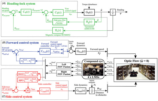
Roubieu et al. [3][17] presented a biomimetic miniature hovercraft to travel along various corridors with the optic flow, which used a minimalistic visual system to measure the lateral optic flow for controlling robots’ clearance from the walls and forward speed in challenging environments, as shown in Figure 1. The restricted field of view is the limitation of the visual perception systems, which may not perform successful navigation in complex environments, such as challenging corridors.
A collision avoidance model based on correlation-type elementary motion detectors with the optic flow in simple or cluttered environments was proposed in [4][18]. It used the depth information from optic flow as input to the collision avoidance algorithm under closed-loop conditions, but the optimal path could not be guaranteed. Yadipour et al. [5][19] developed an optic-flow enrichment model with visual feedback paths and neural control circuits, and the feedback car provided the relative position regulation. The visual feedback model was a bioinspired closed loop, as shown in Figure 2. Dynamics-specialized optic-flow coefficients would be required as an improvement.
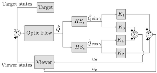
Figure 2. Visual feedback model of an optic-flow enrichment to provide the difference between the viewer and target insect [5].
Visual feedback model of an optic-flow enrichment to provide the difference between the viewer and target insect [19].
A control-theoretic framework was developed for directional motion preferences, and it processed the optic flow in lobula plate tangential cells [6][20]. It simplified the operation of the control architectures and formalized gain synthesis tasks as linear feedback control problems and tactical state estimation. However, it assumed an infinite tunnel environment and small perturbations. Resource-efficient visual processing was proposed in [1][9] with insect-like walking robots such as the mobile platforms shown in Figure 3a, which consisted of image preprocessing, optic flow estimation, navigation, and behavioral control. It supported controlling the collision avoidance behavior by leveraging optimized parallel processing, serialized computing, and direction communication.
However, the major challenges of these perception approaches are dealing with dynamic obstacles. Although the feedback control provides robust operation, dynamic obstacles are not considered or successfully handled. Dynamic environments involve moving obstacles that significantly decrease performance or cause ineffective operation. Detection and tracking of dynamic obstacles still remain difficult for bioinspired perception and navigation. For optic flow, the configurations of the coefficient for a dynamic environment or combination of other sensors are presented as considerations.
An event-based neuromorphic system senses, computes, and learns via asynchronous event-based communication, and the communication module is based on the address-event representation (AER) [7][21]. Action potentials, known as “spikes,” are treated as digital events traveling along axons. Neuromorphic systems integrate complex networks of axons, synapses, and neurons. When a threshold is exceeded, a neuron sends the event to other neurons and fires an action potential [8][22]. The advantages of an event-based visual system include a low power and latency and a high dynamic range and temporal resolution. A spiking neural network (SNN) is suitable for processing the sparse data generated by event-based sensors from spike-based and asynchronous neural models [9][23].
A gradient-based optical flow strategy was applied for neuromorphic motion estimation with GPU-based acceleration, which was suitable for surveillance, security, and tracking in noisy or complex environments [10][7]. The GPU parallel computation could exploit the complex memory hierarchy and distribute the tasks reasonably. Moreover, a single-chip and integrated solution was presented with wide-field integration methods, which were incorporated with the on-chip programmable optic flow, elementary motion detectors, and mismatch compensation [11][24]. It achieved real-time feedback with parallel computation in the analog domain.
Paredes-Valles et al. [9][23] proposed a hierarchical SNN with the event-based vision for a high-bandwidth optical flow estimation. The hierarchical SNN performed global motion perception with unsupervised learning from the raw stimuli. The event camera was categorized as a dynamic vision sensor and used the AER as a communication protocol. An adaptive spiking neuron model was used for varying the input statistics with a novel formulation. Then, the authors used a novel spike-timing-dependent plasticity implementation and SNN for the hierarchical feature extraction.
Another optical estimation with an event-based camera, such as a dynamic and active-pixel vision sensor, was proposed by Zhu et al. [12][25], which presented a self-supervised neural network called EV-FlowNet. A novel, deep learning pipeline fed the image-based representation into a self-supervised neural network. The network recorded data from the camera and was trained without manual labeling. However, the challenging lighting and high-speed motions remained challenging for the neural network.
Two automatic control systems were developed with optical flow and optical scanning sensors, and they could track a target inspired by insects’ visuomotor control systems [13][26]. The visuomotor control loop used elementary motion detectors to extract information from the optical flow. Li et al. [14][27] characterized an adaptive peripheral visual system based on the optical-flow spatial information from elementary motion detector responses. The complementary approach processed and adapted the peripheral information from the visual motion pathway.
de Croon et al. [15][28] developed a motion model combined with the optic flow to accommodate unobservability for attitude control. Optic flow divergence allowed independent flight and could improve redundancy, but it would need more sensors to improve observability. For measuring optical flow, comparative tests of optical flow calculations were presented in [16][29] with the contrast of “time of travel”. Two time-of-travel algorithms relied on cross-correlation or thresholding of adjacent bandpass-filtered visual signals.
Feedback loops were designed to employ the translational optic flow for collision-free navigation in an unpredictable environment [17][30]. The optic flow could be generated as the related motion between the scene and the observer, and the translational optic flow was for short-range navigation. It used the relative linear speed and the distance as the ratio. Igual et al. [18][31] promoted a robust gradient-based optical flow algorithm for robust motion estimation. It could be implemented for tracking or biomedical assistance in a low-power platform, and real-time requirements were satisfied by a multicore digital signal processor, as shown in Figure 4. However, it lacked detailed measurements about power consumption and real measurements for the system and core levels.
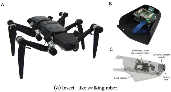
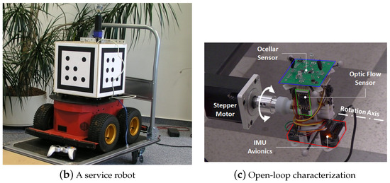
Figure 3. (a) Insect-like walking robot with a bottom view and rendered side view of the front segment. (A) is the hexapod walking robot. (B) is the rendered side view. (C) is the front segment of the robot. It was inspired by the stick insect and adopted the orientation of its legs’ joint axes and the relative positions of its legs [1][9]. (b) A service robot with an omnidirectional vision system and a cube for flexible and robust acquisition [19][2]. (c) Open-loop characterization [20][32].
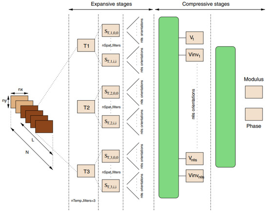
Figure 4. The multichannel gradient model with temporal and spatial filtering, steering, speed and velocity, and direction [18].
The multichannel gradient model with temporal and spatial filtering, steering, speed and velocity, and direction [31].
Zufferey et al. [21][33] designed an ultralight autonomous microflier for small buildings or house environments based on the optic flow with two camera modules, rate gyroscopes, a microcontroller, a Bluetooth radio module, and an anemometer. It could support lateral collision avoidance and airspeed regulation, but the visual textures could be further enhanced. Another vision-based autopilot was later presented with obstacle avoidance and joint speed control via the optic flow in confined indoor environments [22][34], which traveled along corridors by controlling the clearance and speed from walls. The visuomotor control system was a dual-optic-flow regulator.
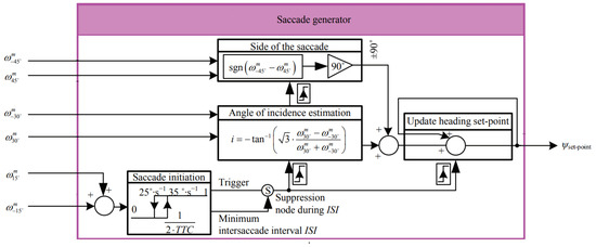
Ref. [23][35] introduced a bioinspired autopilot that combined intersaccadic and body-saccadic systems, and the saccadic system avoided frontal collisions and triggered yawing body saccades based on local optic flow measurements. The dual OF regulator controlled the speed via an intersaccadic system that responded to frontal obstacles, as shown in Figure 5. Ref. [24][36] provided guidelines of navigation based on a wide-field integration of the optic flow, and the wide-field integration enabled motion estimation. The system was lightweight and small for micro air vehicles with low computation requirements. A gyro sensor was combined with the wide-field integration for the estimation.
Serres et al. [25][37] introduced an optic-flow-based autopilot to avoid the corridors and travel safely with a visuomotor feedback loop named Lateral Optic Flow Regulation Autopilot, Mark 1. The feedback loop included a lateral optic flow regulator to adjust the robot’s yaw velocity, and the robot was endowed with natural pitch and roll stabilization characteristics to be guided in confined indoor environments. Ref. [26][38] developed an efficient optical flow algorithm for micro aerial vehicles in indoor environments and used the stereo-based distance to retrieve the velocity.
From the mentioned navigation approaches, the challenges also include hardware and logic limitations and the implemented sensor algorithms. For example, the motion detection architecture [14][27] and optimal spectral extension [10][7] should be improved. Obstacle avoidance logic and control parameters should be investigated more in complex environments [21][23][26][33,35,38]. The challenging lighting environments should also be considered [12][25]. The optimal implementation of algorithms is also a limitation, which may not be satisfied by dynamics models [5][19]. Sensor fusion would be helpful to improve observability [3][15][17,28].
2. SLAM
A simultaneous localization and mapping system (SLAM) can construct a map and calculate the pose simultaneously, so it is implemented with different sensors for localization [27][39]. A heterogeneous architecture was introduced for a bioinspired SLAM for embedded applications to achieve workload partitioning in [27][39], as demonstrated in Figure 6. It used local view cells and pose cell networks for the image processing to improve time performance, although it could not achieve processing on the fly.
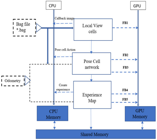
Figure 6.
Schematic representation of functional blocks in the bioinspired SLAM, and
Vidal et al. [28][40] presented a state estimation pipeline for visual-based navigation to combine standard frames, coupled manner events, and inertial measurements for SLAM. The hybrid pipeline provided an accurate and robust state estimation and included standard frames for real-time application in challenging situations. Refocused events fusion was proposed with multiple event cameras for outlier rejection and depth estimation to fuse disparity space images [29][41], and it performed a stereo 3D reconstruction of SLAM and visual odometry. The limitation of that research was the camera tracking algorithm; if the proposed method was integrated with a tracking algorithm, a full event-based stereo SLAM could be achieved.
Another framework based on an event camera was proposed in [30][42] with CNNs. Its solution only relied on event-based camera data and used the neural network for the relative camera depth and pose. The event data were more sensitive to the pose when involving rotations. However, the SLAM solution was limited to an offline implementation, and the used dataset was under a static environment. The proposed networks also had the challenges of parameter size.
Pathmakumar et al. [31][43] described a dirty sample-gathering strategy for cleaning robots with swarm algorithms and a geometrical feature extraction. The approach covered identified dirt locations for cleaning and used geometric signatures to identify dirt-accumulated locations. It used SLAM to get the 2D occupancy grid and ant colony optimization (ACO) for the best cleaning auditing path. Machine-learning-based or olfactory sensing techniques were the next step. An efficient decentralized approach, an immunized token-based approach [32][44], was proposed for an autonomous deployment in burnt or unknown environments to estimate the severity of damage or support rescue efforts. It used SLAM to detect the environment, and the robots carried wireless devices to create communication and sensing coverage.
Jacobson et al. [33][45] introduced a movement-based autonomous calibration technique inspired by rats based on Open RatSLAM, which performed self-motion and place recognition for multisensory configurations. It used a laser, an RGB and range sensor, cameras and sonar sensors for online sensor fusion, and weighting based on the types of environments, including an office and a campus. RatSLAM was improved to enhance its environmental adaptability based on the hue, saturation, and intensity (HSI) color space that handles image saturation and brightness from a biological visual model [34][46]. The algorithm converted the raw RGB data to the HSI color space via a geometry derivation method, then used a homomorphic filter and guided filtering to improve the significance of details.
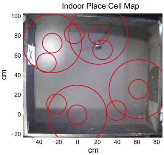
A hierarchical look-ahead trajectory model (HiLAM) was developed by combining RatSLAM and HiLAM, which incorporated media entorhinal grid cells and a hippocampus and prefrontal cortex. It employed RatSLAM for real-time processing and developed the hybrid model based on a serialized batch-processing method [35][47]. Figure 7 shows an indoor place cell map. A slow feature analysis network was applied to perform visual self-localization with a single unsupervised learning rule in [19][2], and it used an omnidirectional mirror and simulated rotational movement to manipulate the image statistics as shown in Figure 3b. It enhanced the self-localization accuracies with LSD-SLAM and ORB-SLAM, but it could have difficulties handling the appearance changes.
The limitations of the proposed SLAM approaches include a lack of support of real-time image processing [27][39] or image detection [34][46] and difficulties in handling environmental changes [19][2]. These make such systems respond slowly or not respond to environmental changes. Moreover, they can cause failures in navigation or make incorrect decisions if visual disturbances exist. More powerful strategies, such as machine learning or neural networks, could be combined to overcome these issues, but they require a comprehensive dataset generation [31][43]. Parallel processing could also be used as a solution [27][39].
3. Landmark
Sadeghi Amjadi et al. [36][48] put forward a self-adaptive landmark-based navigation inspired by bees and ants, and robots located the cue by their relative position. The landmark of this navigation method used a QR code to identify the environment and employed a camera for the relative distance by perspective-n-point algorithms. It was adaptive to environmental changes but lacked any consideration of the presence of stationary and moving objects. Ref. [37][49] compared landmark-based approaches, including average landmark vector, average correctional vector, and distance estimated landmark vector approaches, and proposed a landmark vector algorithm using retinal images. The results showed that the distance estimated landmark vector algorithm performed more robust homing navigation with occluded or missing landmarks than others.
Maravall et al. [38][5] designed an autonomous navigation and self-semantic location algorithm for indoor drones based on visual topological maps and entropy-based vision. It supported robot homing and searching and had online capabilities because of metric maps and a conventional bug algorithm. The implementation of other situations should be analyzed further. Ref. [39][50] introduced a pan–tilt-based visual system as a low-altitude reconnaissance strategy based on a perception-motion dynamics loop and a scheme of active perception. The dynamics loop based on chaotic evolution could converge the periodic orbits and implement continuous navigation. The computational performance was not analyzed. A new data structure for landmarks was developed as a landmark-tree map with an omnidirectional camera, and it presented a novel mapping strategy with a hierarchic and nonmetric nature to overcome memory limitations [40][51]. However, its feature tracker could not support long distances.
Although some self-adaptive frameworks were proposed, dynamic obstacles were not considered [36][37][40][48,49,51]. Object tracking is also a bottleneck for the landmark-based approach if the landmark is moving over large distances. Some papers’ implementations or experiments are difficult to conduct due to the situations under certain environments or hardware limitations [36][38][5,48]. The computational performance of the system should develop a measurement strategy.
4. Others
Proper vergence control reduces the search space and simplifies the related algorithms, and a bioinspired vergence control for a binocular active vision system was introduced in [41][8]. It controlled the binocular coordination of camera movements to offer real-world operation and allow an exploration of the environment. Salih et al. [42][52] developed a vision-based approach for security robots with wireless cameras, and the approach used a principal component analysis algorithm for image processing, a particle filter for images, and a contour model. The system could recognize objects independently in all light conditions for frame tracking.
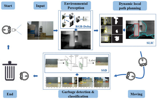
A camera-based autonomous navigation system was conceptualized for floor-sweeping robots in [43][6], including inspection, targeting, environment perception, local path planning, and directional calibration, as demonstrated in Figure 8. It achieved image processing and map planning by a superpixel image segment algorithm, but it could interfere with light. Cheng et al. [44][53] designed a distributed approach with networked wireless vision sensors and mosaic eyes. It performed localization, image processing, and robot navigation with multiple modules and obtained real-time obstacle coordinates and robot locations. The limitation of the work was the coordination of multiple cameras; the framework could be further improved for mapping the images to a workspace.
Li et al. [45][54] developed a parallel-mechanism-based docking system with the onboard visual perception of active infrared signals or passive markers. The modules performed docking based on relative positioning, and the self-assembly robot could react to different environments, such as stairs, gaps, or obstacles. However, the applications of the docking system were limited without a positioning system. Ref. [46][55] conceptualized a lightweight signal processing and control architecture with visual tools and used a custom OpenGL application for real-time processing. The novel visual tool was inspired by a vector field design for exploiting the dynamics and aiding behavioral primitives with signal processing. The control law and schemes could be improved in that framework.
Boudra et al. [47][56] introduced a mobile robot’s cooperation and navigation based on visual servoing, which controlled the angular and linear velocities of the multiple robots. The interaction matrix was developed to combine the images with velocities and estimate the depth of the target and each robot, although it could not be applied to 3D parameters. Ahmad et al. [48][57] developed a probabilistic depth perception with an artificial potential field (APF) and a particle filter (PF), formulating the repulsive action as a partially observable Markov decision process. It supported 3D solutions in real time with raw sensor data and directly used depth images to track scene objects with the PF. The model could not address the problem of dynamic obstacles or dynamic prediction.
An ocular visual system was designed for a visual simulation environment based on electrophysiological, behavioral, and anatomical data with a fully analog-printed circuit board sensor [20][32]. The model used a Monte Carlo simulation for linear measurements, an open-loop sensor characterization, and close-loop stabilizing feedback, as displayed in Figure 3c. Nguyen et al. [49][58] described an appearance-based visual-teach-and-repeat model to follow a desired route in a GPS-denied environment. The repeated phases made the robot navigate along the route with reference images and determine the current segment by self-localization by sped-up robust features to match images. An effective fusion of sensors could be further required.
A probabilistic framework was presented with a server–client mechanism using monocular vision for terrain perception by a reconfigurable biomimetic robot [50][59]. GPGPU coding performed real-time image processing, and it supported the unsupervised terrain classification. The perception module could be extended with an IMU sensor. Montiel-Ross et al. [51][60] proposed a stereoscopic vision approach without depth estimation, which used an adaptive candidate matching window for block matching to improve accuracy and efficiency. The global planning was achieved through simple ACO with distance optimization and memory capability, and the obstacle and surface ground detection were achieved by hue and luminance.
Aznar et al. [52][61] modeled a multi-UAV swam deployment with a fully decentralized visual system to cover an unknown area. It had a low computing load and provided more adaptable behaviors in complex indoor environments. An ad hoc communication network established communications within the zone. A V-shaped formation control approach with binoculars was applied to the robotic swarms for unknown region exploration in [53][62] with a leader–follower structure. The formation control applied a finite-state machine with a behavior-based formation-forming approach, considering obstacle avoidance and anticollision. However, the physical application was a challenge due to the devices, such as the physical emitter or sensor [20][50][53][32,59,62]. The indirect communication between a swarm of robots or a sensor-based communication protocol is hard to achieve [52][53][61,62].

