Design for disassembly is currently conducted with costly and time-consuming mechanical joints. Now, mortar joints with much weaker mortar types are proposed for new buildings, enabling easier disassembly by new methods: removal by direct pulling and removal by use of a system of flat jacks. Different weak mortar types were tested in the lab to achieve the properties required to check the transfer of wind loads and the level of resistance to separation during disassembly. Using a modelled case study building, the results showed that weak lime cement-based mortars had the required properties to substitute regular cement-based mortar in joints between slabs and a stabilising wall during a critical wind load. Regarding disassembly, pulling concrete slabs out with a mobile crane would be possible if hydro demolition systems could be implemented to remove parts of the mortar joint beforehand.
1. Buildings Covered by the DfD Method
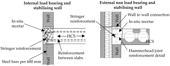
The required joint mortar strength depends on the specific geometry of the building and should be calculated for each design case. The transfer of forces between precast concrete elements is critical for concrete frame buildings consisting of slabs, beams, and columns, with a stabilising system of few walls. A wind load acting on the façade of a building is distributed to the floor diaphragm of each storey and via the floors to the stabilising walls. The primary concern related to the strength of the mortar during the service of the building is the connection details between floors and stabilising walls, where the in-plane forces from the floors are transferred via the mortar and reinforcement steel to become in-plane forces in the walls. Such typical connection detail with hammerhead joints is seen in Figure 1.
Figure 1.
Hollow Core Slab (HCS) to wall connection details. Left: Span of HCS perpendicular to the wall. Right: Span of HCS parallel to the wall.
The interface between Hollow Core Slab (HCS) and mortar, the mortar itself, and the interface from mortar to the wall must be able to transfer the required shear due to the wind load. Traditionally, steel reinforcement is present through both interfaces, and stringer reinforcement is placed longitudinally above the wall inside the mortar. The transfer of shear can occur in combination with a normal force.
2. Disassembly Process with Weak Mortar Joints
The assembly process is assumed to be the same as traditional precast concrete buildings with the in-situ pouring of the mortar and steel reinforcement bars in the joints. Nevertheless, from an analysed data output, it was found that there is a need to reduce special adaptations in future building designs. It should be preferred to position the reinforcement steel in the joints between the precast elements instead of into the elements. Also, very thick layers of screed should be avoided.
The disassembly process relies on an easy separation between slabs and other elements. To have an effective DfD solution for the whole building, the walls, beams, and columns should also be designed for dismantling, though that process is not considered here. The above storeys are assumed to have been removed, including the stabilising walls above the considered floor. The most optimal dismantling process may change depending on the specific mortar strength and building geometry. Edge beams and edge reinforcement should always be removed beforehand to be recycled:
Level 1: The slabs can be removed simply by grabbing and pulling with a mobile crane. The pulling resistance can be reduced by applying hydro demolition water jet systems to remove parts of the mortar;
Level 2: A flat jacking system is required to force the separation of the slabs before pulling them out with a mobile crane. The method is combined with hydro demolition water jets to reduce the necessary jacking force;
Level 3: If none of the above methods is applicable, diamond sawing is still required, like the current practice.
In many buildings, it may be necessary to cut the reinforcement at the corners of the slabs. This ensures the steel does not fixate the separation between mortar and precast concrete when a slab is lifted away. Since edge beams are removed beforehand, there is always one free side of the first slab near the edge of the building—and therefore, similarly, there is one side free of all other slabs being removed subsequently.
Level 1 is for the weakest types of mortar, where the vertical force of a mobile crane is sufficient to form cracks along the attached slab sides and then overcome the shear resistance of the joints to free the element. The method requires that the slab and the surrounding elements are strong enough to resist the pull without cracking and that the crane pulling force can be controlled slowly to avoid sudden dangerous movements. In most cases, the longitudinal edge of the slab must be removed by, for instance, controlled hydro demolition to reduce the pulling force significantly. A powerful water jet of up to 3000 bars removes parts of or the whole of the joints. Remote-controlled hydro demolition machines with a predefined area and depth of application exist to ensure precise removal of the mortar without creating excessive damage in the adjacent concrete. A benefit of hydro demolition is that the dust from the removed mortar is contained in the water, which can be cleaned and reused repeatedly. Furthermore, the water jets do not harm the reinforcement. Therefore, cutting the reinforcement at the corners of the slabs can be performed after the hydro demolition process with just an ordinary angle grinder.
Level 2 uses flat jacks inside the joints between slabs to force the slabs apart when applying oil pressure. The method requires space for the flat jacks (at least 40 mm) between the elements. The slab resistance must be calculated to ensure that the local force application does not harm the elements by causing cracking. HCSs have a very thin side between the side of the slab and the first hole, and applying a concentrated force on the side may cause penetration into the hole. It may, therefore, again be necessary to remove parts of the mortar by hydro demolition before applying the jacks or to overcome this problem in another way.
3. Case Study Building Description and Modelling
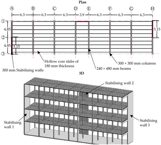
To show the proposed method in a case study, a building was designed with “extreme” geometry to increase the stresses in the joints to a maximum so that the results apply to almost any building configuration of the same size or smaller. The worst-case scenario was with a large destabilising wind load and only a few stabilising walls positioned far apart. The building had the following characteristics, as seen in Figure 2:
Figure 2. Plan- and 3D-drawing of the structural system of the case study building with “extreme” geometry. Letters A to H and numbers 1 to 3 are modular lines.
The HCSs applied in the building were 180 mm thick and 1.2 m wide, with five 9.3 pre-tensioning strands at the bottom. The slabs also exist with a width of 2.4 m as an alternative. The dead load of the floors, including super-imposed loads, was 3.5 kN/m2. The beams had rectangular cross-sections with six 12.5 pre-tensioning strands at the bottom and two at the top.
The building was assumed to be positioned in Denmark, where the wind load is most relevant to investigate as a horizontal load case. The wind load was found via the Eurocodes. The wind on a façade was distributed as a line load on the floors, and it would then be transferred via the floors to the stabilising walls. The total design wind load was 140 kN on each storey for the specific geometry and location. This force was divided equally with 70 kN into the stabilising walls at each end of the building.
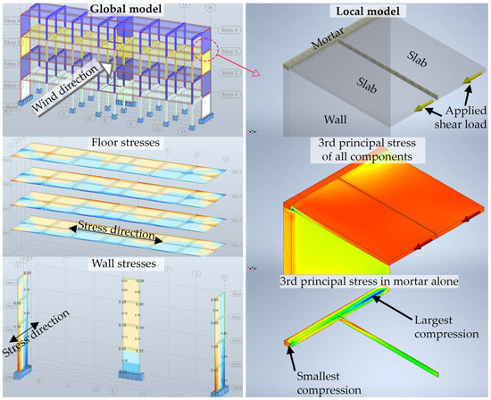
Two models were made with the software Autodesk Robot Structural Analysis (global model) and Autodesk Inventor (local model). The global model was created to visualise the stresses in the walls and slabs with self-weight and the critical wind load applied. Calculations were also performed analytically, which is not shown here since the focus was on the connections and the floor diaphragm. In Figure 3, example stresses in the slabs are visualised for the longitudinal direction of the building, and the stresses in the walls are visualised in the transverse direction. The local model was limited to the critical area of the first two slabs connected to the wall in one of the storeys with the largest wind load applied. For different mortar types, the material properties (e.g., Young’s modulus) of the mortar could be changed, and the new corresponding maximum stresses in the mortar could be found after rerunning the model. The local model was conservatively created without the reinforcement (like the left side of Figure 1) so that all forces were transferred via the mortar from the slabs to the wall.
Figure 3. Global and local model and stress distribution examples. A 2.4 m wide slab was used in the local model for easier modelling. Letters A to H are modular lines. The largest compression is blue and the smallest compression is red.
In the bottom right corner of Figure 3, the 3rd principal stress is applied as the output showing the maximum compression in the mortar alone. Similarly, the largest tension was found as the 1st principal stress in the model. In the example in Figure 3, Young’s modulus was set to 1.4 GPa, and for all mortars with low stiffness, the distribution of stresses would look similar.
After presenting the results from laboratory tests of different weak mortar types, the most appropriate mortar type for the case study building is determined. Read the full publication for more information.