Your browser does not fully support modern features. Please upgrade for a smoother experience.
Please note this is a comparison between Version 1 by Jiepu Li and Version 2 by Jason Zhu.
Type IV hydrogen storage cylinders comprise a polymer liner and offer advantages such as lightweight construction, high hydrogen storage density, and good fatigue performance. However, they are also characterized by higher hydrogen permeability. Consequently, it is crucial for the polymer liner material to exhibit excellent resistance to hydrogen permeation. International organizations have established relevant standards mandating hydrogen permeation tests for the liner material of type IV on-board hydrogen storage cylinders.
- hydrogen storage cylinder
- liner material
- polymer
1. Sample Preparation
The sample preparation methods required for hydrogen permeation tests CSA ANSI CHMC 2, ISO 11114-5, and T/CATSI 02 007 are shown in Table 1.
Table 1.
Comparison of the sample preparation requirements imposed by various standards.
| Standard | CSA ANSI CHMC 2 | ISO 11114-5 | T/CATSI 02 007 |
|---|---|---|---|
| Sample source | Sample from polymer liner or prepared from polymer liner produced using same molding process as the product | Same as CSA ANSI CHMC 2 | Sample from polymer liner |
CSA ANSI CHMC 2 requires a sample thickness between 1 mm and 6 mm, with a preference for a sample with the same thickness as the liner. On the other hand, both ISO 11114-5 and T/CATSI 02 007 stipulate that the sample thickness should equal the liner thickness. It is important to avoid machining the sample to change its thickness, as this may create new defects on its surface, thus affecting the hydrogen permeation test results. Therefore, when conducting a hydrogen permeation test for a specific liner material, it is recommended to select the liner thickness as the sample thickness. Furthermore, Fujiwara [2][41] studied the relationship between the thicknesses of different samples and the diffusion coefficient delay time and verified a linear relationship between the square of the sample thickness and the delay time. This relationship conforms to Formula (4) of the diffusion coefficient. However, since the hydrogen permeability coefficient is determined by both the diffusion and solubility coefficients, whether the sample thickness has a linear relationship with the hydrogen permeability coefficient requires further verification through experimental research.
In summary, the hydrogen permeation test should consider the influence of the molding process and weld defects of the liner material and determine appropriate sample preparation requirements and sampling position. When discussing the specific reasons in depth, they may be closely related to polymer material properties such as molecular chains, crystallinity, and additives.
2. Sample Pretreatment
The sample pretreatment requirements for CSA ANSI CHMC 2, ISO 11114-5, and T/CATSI 02 007 are shown in Table 2.
Table 2.
Comparison of sample pretreatment requirements imposed by various standards.
| Standard | CSA ANSI CHMC 2 | ISO 11114-5 | T/CATSI 02 007 |
|---|---|---|---|
| Drying temperature | Recommend 60 °C | Recommend 65 °C | Unspecified |
Regarding the drying temperature, CSA ANSI CHMC 2 recommends a drying temperature of 60 °C; ISO 11114-5 recommends 65 °C, and T/CATSI 02 007 does not give a specific temperature. A study by Emanuele Parodi et al. [4][48] revealed that PA6, an adipose polyamide consisting of amide and carbonyl groups, exhibited strong hygroscopicity due to its polar character. When exposed to a humid environment, PA6 absorbs water up to a saturation level, resulting in the breaking of hydrogen bonds between the chains and the formation of new hydrogen bonds with the absorbed water molecules. This phenomenon leads to plasticization and depression of the glass transition temperature, resulting in considerable degradation of the mechanical properties.
Currently, there are numerous studies on the effect of humidity on the crystal structure and mechanical properties of polymer materials, but there is limited research and test data on the hydrogen permeability of liner materials for on-board hydrogen storage cylinders under varying humidity conditions. If the actual working conditions of the liner material are not considered, the sample should be dried during the hydrogen permeability test. It is recommended to keep the drying temperature below the softening temperature of the liner material to prevent softening from affecting test result consistency. However, since on-board hydrogen storage cylinders may operate in high-temperature, high-pressure, and high-humidity environments, it is essential to study the comprehensive influence of humidity, coupled with hydrogen temperature and pressure, on the hydrogen permeability of the liner material to ensure that the hydrogen permeation performance of the liner material meets applicable requirements under high-humidity conditions.
3. Test Device
The test devices used in CSA ANSI CHMC 2, ISO 11114-5, and T/CATSI 02 007 are shown in Table 3.
Table 3.
Comparison of the test devices used by the different standards.
| Standard | CSA ANSI CHMC 2 | ISO 11114-5 | T/CATSI 02 007 |
|---|---|---|---|
| ISO 11114-5 | T/CATSI 02 007 | ||
| Device structure diagram | 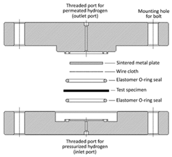 |
 |
Unspecified |
| Test temperature and pressure | (85 ± 1) °C, 1.25 NWP, (15 ± 1) °C, 1.25 NWP, (85 ± 1) °C, 0.1 NWP, (15 ± 1) °C, 0.1 NWP. |
Test should be carried out at a certain pressure and temperature | (55 ± 1) °C, 1.15 NWP, (15 ± 1) °C, NWP, (55 ± 1) °C, 0.1 MPa, (15 ± 1) °C, 0.1 MPa. |
As shown in Table 4, ISO11114-5 stipulates that the hydrogen permeation test should be carried out at a certain pressure and temperature, but these values are not specified. However, the test temperature and pressure specifications differ for the other two standards. CSA ANSI CHMC 2 requires the sample to undergo a permeation test at pressures of 0.1 NWP and 1.25 NWP, as well as at test temperatures of 85 °C and 15 ± 5 °C. T/CATSI 02 007 specifies permeation tests at pressures of 0.1 MPa and 1.15 NWP, and at maximum ambient temperatures of 55 ± 1 °C and 15 ± 5 °C.
The choice of test temperature should align with the working conditions and service environment. A maximum allowable temperature of 85 °C is reached temporarily during the filling of on-board hydrogen storage cylinders. Since hydrogen refueling stations are open spaces where hydrogen does not accumulate easily, temperatures above 50 °C can persist for weeks in desert areas [10][55]. However, in confined spaces such as garages, where hydrogen fuel cell vehicles may be parked for extended periods, hydrogen permeation into the space can cause hydrogen accumulation, leading to potential hazards. Therefore, a high-temperature hydrogen permeation test temperature of 55 °C seems reasonable.
Hydrogen storage systems utilize the SAEJ 2601 filling protocol, where the maximum filling density (100% SOC) of the on-board hydrogen storage system is achieved at a hydrogen temperature of 85 °C and a filling pressure of 1.25 NWP. Conversely, the filling pressure required to reach 100% SOC is NWP at 15 °C and 1.15 NWP at 55 °C [12][56]. Therefore, a high-temperature, high-pressure hydrogen permeation test conducted at 55 °C and 1.15 NWP is more representative of actual working conditions. CSA ANSI CHMC 2 specifies a pressure of 1.25 NWP for normal-temperature, high-pressure hydrogen permeation tests. Considering that cylinders are used in a normal-temperature environment where gas pressure does not exceed the nominal working pressure, it is more reasonable to perform these tests at 15 °C and the nominal working pressure. Additionally, gas cylinders may be in a no-load state with a slight positive pressure for extended periods. Therefore, it is more reasonable to perform normal-temperature, high-pressure hydrogen permeation tests at 15 °C and the nominal working pressure. In addition, since the gas cylinder may be in a no-load state with a slight positive pressure for a long time, it is more reasonable to use a no-load pressure of 0.1 MPa during a hydrogen permeation test in order to verify the hydrogen permeability of the liner material in a no-load state.
5. Qualification Indicators
The CSA ANSI CHMC 2, ISO 11114-5, and T/CATSI 02 007 standard hydrogen permeation test qualification indicators are shown in Table 5.
Table 5.
Comparison of qualification indicators defined by various standards.
| Standard | CSA ANSI CHMC 2 | ISO 11114-5 | T/CATSI 02 007 | |||
|---|---|---|---|---|---|---|
| Qualification indicators | The steady-state gas transmission rate measured at 15 °C for a sample with a diameter of 78 mm is divided into six rating values: 10: ≤0.8 Ncm³/h, 8: >0.8–1.5 Ncm³/h, 6: >1.5–3 Ncm³/h, 4: >3–6 Ncm³/h, 2: >6–16 Ncm³/h, and 0: >16 Ncm³/h. |
Unspecified | At 15 °C, Pe ≤ 1 × 10⁻¹³ cm3·cm/(cm2·s·Pa), At 55 °C, Pe ≤ 1 × 10⁻¹² cm3·cm/(cm2·s·Pa) |
|||
| Sampling position | Unspecified | |||||
| Vacuum pressure | Unspecified | Unspecified | Seamless liner: middle of cylinder Welded liner: middle of cylinder away from the welding seam | |||
| Recommend 10–50 mbar | ||||||
| Test Method | HPHP method | HPHP method | Unspecified | HPHP method | Diameter (mm) | ≥25 mm (recommend 78) |
| Vacuum drying finish conditions | Mass loss rate within 48 h or 1 h of drying is <0.5% | Between 40 mm and 80 mm | 78 mm | |||
| The mass loss rate within 24 h of drying is <0.1% | Unspecified | Thickness (mm) | 1 ≤ liner thickness ≤ 6 (recommend liner thickness) | Liner thickness | Liner thickness |
As shown in Table 1, different standards have varying requirements for hydrogen permeation samples. CSA ANSI CHMC 2 and ISO 11114-5 specify that samples should be prepared from the polymer liner. If a comparison of hydrogen permeation performance among multiple liner materials is required, samples can be prepared from polymers produced using the same molding process as the final product. However, the above two standards do not specify sampling position requirements. T/CATSI 02 007 stipulates that samples can be prepared from the polymer liner. For seamless liners, the sampling position is located in the middle of the cylinder, while for welded liners, it is located in the middle of the cylinder, away from the welding seam. Regarding the sample source, when samples are prepared from polymers produced using the same molding process as the final product, material grade and heat treatment processes, such as curing, can affect the hydrogen permeability characteristics of the polymer liner material. Additionally, the sample may have defects, such as wrinkles, creases, and gas cavities formed during molding. Differences in the molding processes used with the prepared specimen and the final product can impact the representativeness of test results [1][43]. Therefore, if the sample is prepared using the same process as the liner product, it is necessary to specify that the process flow and heat treatment method are consistent with that used to make the liner and that the prepared sample should not have manufacturing defects that affect test results.
In terms of sampling position, injection-molded liners with welds may have defects such as wrinkles, creases, and gas cavities near the weld, which can affect the hydrogen permeability at the welding seam of the liner. There is still a lack of systematic research on the hydrogen permeability at the welding seam of the liner material for the type IV on-board hydrogen storage cylinders. Therefore, it is necessary to study the performance at the welding seam to ensure that the plastic liner hydrogen permeation test considers the area with the weakest hydrogen permeability.
As shown in Table 2, each standard requires heated drying and vacuum degassing of samples before hydrogen permeation testing. ISO 11114-5 recommends a vacuum pressure of 10–50 mbar, whereas CSA ANSI CHMC 2 and T/CATSI 02 007 do not specify the vacuum pressure. Regarding finishing conditions, CSA ANSI CHMC 2 requires that the mass loss rate within 48 h or 1 h of drying is <0.5%, and ISO 11114-5 requires a mass loss rate within 24 h of drying of <0.1%. It is worth noting that volatile organic compounds (VOCs) from polymer exhaust can affect hydrogen compatibility evaluation test results [3][22]. Therefore, it is suggested that the liner hydrogen permeation test specifications clarify the required vacuum pressure and specify the mass loss rate of the sample at the end of vacuum drying to ensure that the polymer sample completes the exhaust process.
| Sintered metal plate porosity | |||
| Porosity reaches grade 2 | Unspecified | Unspecified | |
| Wire mesh size | 140 μm | 150 μm | Unspecified |
| Hydrogen exposure zone diameter | ≥di mm | ≥di mm | ≥di mm |
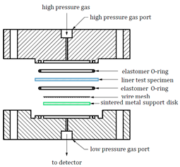
As shown in Table 3, the hydrogen permeation device structures described in the CSA ANSI CHMC 2 and ISO 11114-5 standards are nearly identical, but T/CATSI 02 007 does not specify a test device. Each standard uses the HPHP test method. The test device in the CSA ANSI CHMC 2 and ISO 11114-5 standards mainly consists of a high-pressure sealing cavity, a low-pressure sealing cavity, sealing rings, a wire mesh, and a sintered metal plate. The high-pressure and low-pressure sealed chambers are used to hold samples, while sintered metal plates support wafer specimens to prevent the sample from being squeezed and deformed under high-pressure gas. The wire mesh is placed between the sample and the sintered metal plate to avoid direct contact between the sintered metal and the sample surface and to ensure that hydrogen permeating from the sintered metal is distributed evenly in the exposed area of the sample.
The HPHP method is based on the differential pressure method proposed by Barrier and Brubaker et al. [5][6][7][49,50,51], optimized and improved by integrating the ASTM 1434 and ISO 7229 standards, which were used to measure gas permeation properties at equilibrium. In this method, the sample is placed between the high- and low-pressure chambers, and the gas permeability coefficient is determined by measuring the amount of gas that permeates to the low-pressure chamber. Yamabe et al. [8][52] also proposed a thermal desorption analysis (TDA) method for measuring the hydrogen permeability coefficient. The sample was exposed to high-pressure hydrogen, and then the emission (elimination) of hydrogen from the polymer material was measured using a gas chromatograph in a non-equilibrium state. The gas permeability and diffusion coefficients were calculated by function fitting. Fujiwara [9][53] compared hydrogen permeability data of different polymer materials measured by the TDA and HPHP methods.
Regarding the sintered metal plate porosity, CSA ANSI CHMC 2 stipulates that the sintered metal should have a porosity of Grade 2 to ensure that the gas transmission rate of the plate is at least 100 times greater than that of the liner specimen, preventing the gas barrier properties of the sintered metal from affecting test results. Both CSA ANSI CHMC 2 and ISO 11114-5 recommend placing a 140 μm and 150 μm wire mesh, respectively, between the polymer specimen and the porous plate. Since the gas transmission rate of the wire mesh is significantly higher than that of the polymers, the mesh size has no effect on the hydrogen permeation test results [10][55]. Regarding the hydrogen leakage zone diameter, CSA ANSI CHMC 2 and T/CATSI 02 007 stipulate that it should be greater than or equal to 25 mm, while ISO 11114-5 requires it to be greater than or equal to 30 mm. Theoretically, the amount of hydrogen permeation is proportional to the hydrogen exposure zone diameter, and different hydrogen permeation areas should not affect the hydrogen permeation coefficient. However, some studies have shown that the measured gas permeability coefficient of a sample may appear high when the hydrogen permeation area is small. This could be due to non-isotropic hydrogen diffusion in the thickness direction of the liner [11][46]. Therefore, further research is needed to understand the influence of the hydrogen exposure zone diameter on hydrogen permeability to determine the appropriate diameter range.
In summary, the three standards define test devices with similar principles and structures, and all use the HPHP method. However, this method requires a higher sealing effect for the O rings. The effect of the O ring hydrogen permeability coefficient cannot be accurately judged due to the existing test device being sealed via sealing rings. Additionally, since the sample diameter is larger than that of the sealing rings, hydrogen may escape from the sample edge. Hence, it is necessary to optimize the structure of the existing test device to improve hydrogen permeation test accuracy.
4. Test Temperature and Pressure
The CSA ANSI CHMC 2, ISO 11114-5, and T/CATSI 02 007 temperatures and pressures are shown in Table 4.
Table 4.
Comparison of test temperatures and pressures.
| Standard | CSA ANSI CHMC 2 |
|---|
As shown in Table 5, the ISO 11114-5 standard does not specify hydrogen permeation test qualification indicators. However, for type-IV hydrogen storage cylinders, the steady-state hydrogen permeability rate should meet certain criteria. It should be less than 46 NmL/(h·L) at 1.15 NWP and 55 °C and less than 6 NmL/(h·L) at NWP and 15 °C [10][13][14][21,55,57]. T/CATSI 02 007 assigns a maximum allowable hydrogen permeability coefficient value range to each gas cylinder volume range. The hydrogen permeability coefficient of the polymer liner material should not exceed 2 × 10⁻¹³ cm3·cm/(cm2·s·Pa) at 15 °C or 1 × 10⁻¹² cm3·cm/(cm2·s·Pa) at 55 °C. Based on a requirement of 6 NmL/(h·L) for a 60 L cylinder, the CSA ANSI CHMC 2 standard uses a different approach by stipulating that the steady-state gas transmission rate measured at 15 °C for a sample with a diameter of 78 mm be divided into six rating values. Grade 0 indicates the material with the worst hydrogen barrier properties, and grade 10 represents the material with the best hydrogen barrier properties. This quantitative classification of the hydrogen transmission rate provides a standardized system for comparing the hydrogen permeation performances of different materials. Based on specific hydrogen system application scenarios, the minimum acceptable hydrogen permeation test rating value can be specified, providing a clear range of hydrogen permeability coefficient values. This allows for a more accurate evaluation of material suitability for hydrogen storage applications.
In summary, the quantitative classification of the hydrogen transmission rate provides a valuable means to compare the hydrogen permeation performances of various polymer materials. The minimum acceptable hydrogen permeation test rating value can be adjusted based on the specific requirements of different compressed hydrogen systems. However, when using the hydrogen permeation test method to assess whether a chosen liner material possesses good hydrogen permeation resistance, it is advisable to establish a maximum allowable hydrogen permeability coefficient range for the liner material. This can be determined by considering the hydrogen permeation test indicators of gas cylinders and the volume range of gas cylinders. Setting such limits ensures that the selected liner material meets the necessary hydrogen barrier properties for practical applications in different gas storage systems.