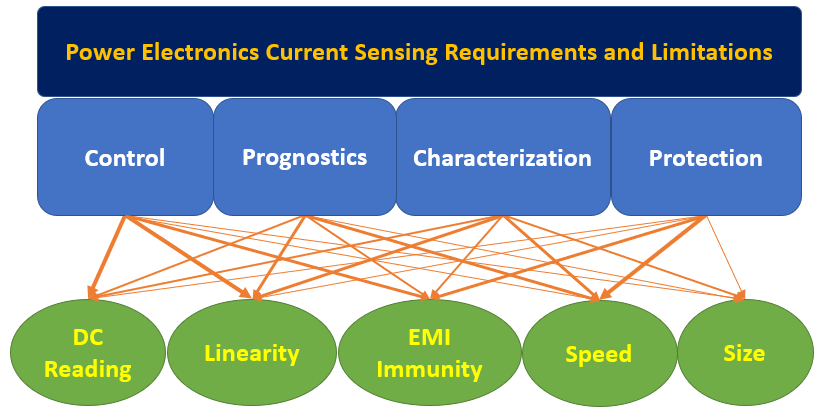
A current sensor is a device exploited to measure electric currents, either alternating current (AC) or direct current (DC). These devices are used in various applications, including detecting faults, monitoring performance (for control or prognostics), and detecting changes in system behavior. Power applications employ various current-monitoring products to control, characterize, and monitor the current flow. Current sensors, for example, are used in power lines to measure the flow of the current, for controlling current flow, or detect overcurrent or excess currents.
- current sensing
- WBG power converters
- integration challenges
1. Current-Sensing Methods in Power Electronics Applications
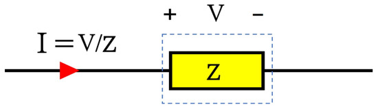
2. Ohmic Current Sensors
3. DC Magnetometers
3.1. Hall-Effect Sensors
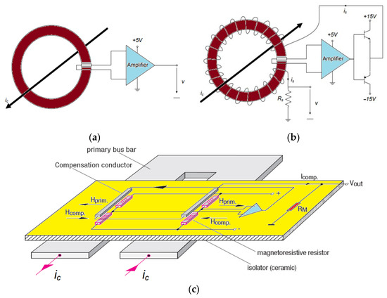
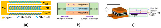
3.2. Magnetoresistive Sensors
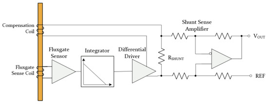
3.3. Fluxgate Sensors
4. Inductive Current Sensors
4.1. Current Transformer
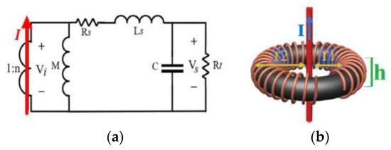
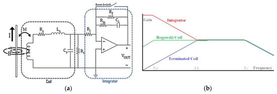
4.2. Rogowski Coil
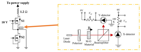
5. Magneto-Optical Current Sensing

6. Hybrid Current Sensing
6. Hybrid Current Sensing
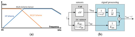
Upon reviewing the information presented in the previous sections, it becomes apparent that there is no perfect single-path current -sensing method with all desirable properties that can be integrated into WBG power converters as a general solution. It is nevertheless possible to combine different single-scheme methods to achieve the desired performance in a given application, particularly when the complementary BW compensation method is used, as illustrated in Figure 9. This can range from simple current -sensing systems to advanced multi-sensory schemes. Ultimately, the selection of a sensing arrangement should be based on the specific requirements of the application. Historically, hybrid configurations have been underutilized in a variety of power electronics applications, in which two single-scheme current -measurement methods are combined to compensate for their limited bandwidth [14, 38, 48, 49, 88-92][1][25][26][27][28][29][30][31][32]. Using hybrid (or dual-scheme) configurations can increase the accuracy, speed, and BW of a sensing system, which is especially beneficial in high-frequency applications as a single measurement method may not provide enough BW [14][1].
Even though hybrid configurations may provide more viable solutions than single-path sensing systems, one of the disadvantages of hybrid configurations is that they can be more difficult to design and implement than single-path sensing systems, asnd well asthey can also require complex layout considerations. Due to the combination of multiple sensing methods that can introduce errors associated with every single sub-measurement system in multi-scheme configurations, they are less reliable than simple systems. A number of integration issues can be considered when considering multi-scheme current sensors for power electronics, as previously discussed in this review. These challenges may limit the size, circuit invasion, EMI immunity, and other options of multi-scheme current sensors. Therefore, it is essential to understand how to properly select multi-scheme current sensors in order to improve the integration of these sensors into WBG power converters and maximize their performance.

References
- Xin, Z.; Li, H.; Liu, Q.; Loh, P.C. A Review of Megahertz Current Sensors for Megahertz Power Converters. IEEE Trans. Power Electron. 2022, 37, 6720–6738.
- Shao, S.; Yu, N.; Xu, X.; Bai, J.; Wu, X.; Zhang, J. Tunnel Magnetoresistance-Based Short-Circuit and Over-Current Protection for IGBT Module. IEEE Trans. Power Electron. 2020, 35, 10930–10944.
- Roy, C.; Kim, N.; Niakan, H.; Parsa Sirat, A.; Parkhideh, B. An Ultra-Fast and Non-Invasive Short Circuit Protection Strategy for a WBG Power Electronics Converter with Multiple Half-Bridge Legs. In Proceedings of the 2020 IEEE Energy Conversion Congress and Exposition (ECCE), Detroit, MI, USA, 11–15 October 2020; pp. 2505–2510.
- Nibir, S.J.; Parkhideh, B. Magnetoresistor with Planar Magnetic Concentrator as Wideband Contactless Current Sensor for Power Electronics Applications. IEEE Trans. Ind. Electron. 2018, 65, 2766–2774.
- Ziegler, S.; Woodward, R.C.; Iu, H.H.-C.; Borle, L.J. Current Sensing Techniques: A Review. IEEE Sens. J. 2009, 9, 354–376.
- Patel, A.; Ferdowsi, M. Current Sensing for Automotive Electronics—A Survey. IEEE Trans. Veh. Technol. 2009, 58, 4108–4119.
- Qi, Z.; Pei, Y.; Wang, L.; Ma, Z.; Zhang, Z.; Wang, Y.; Wang, K.; Yang, X. A High-Bandwidth and Easy-to-Integrate Parasitics-Based Switching Current Measurement Method for Fast GaN Devices. IEEE Trans. Power Electron. 2023, 38, 447–459.
- Shillaber, L.; Jiang, Y.; Ran, L.; Long, T. Ultrafast Current Shunt (UFCS): A Gigahertz Bandwidth Ultra-Low-Inductance Current Sensor. IEEE Trans. Power Electron. 2022, 37, 15493–15504.
- Wickramasinghe, T.; Allard, B.; Buttay, C.; Joubert, C.; Martin, C.; Mogniotte, J.-F.; Morel, H.; Bevilacqua, P.; Le, T.-L.; Azzopardi, S. A Study on Shunt Resistor-Based Current Measurements for Fast Switching GaN Devices. In Proceedings of the IECON 2019—45th Annual Conference of the IEEE Industrial Electronics Society, Lisbon, Portugal, 14–17 October 2019; Volume 1, pp. 1573–1578.
- Caruso, M.J. A New Perspective on Magnetic Field Sensing. Sensors 1998, 15, 34–46.
- Díaz-Michelena, M. Small Magnetic Sensors for Space Applications. Sensors 2009, 9, 2271–2288.
- Lenz, J.; Edelstein, S. Magnetic Sensors and Their Applications. IEEE Sens. J. 2006, 6, 631–649.
- Hall Effect Devices; CRC Press: Boca Raton, FL, USA, 2003.
- Paun, M.-A.; Sallese, J.-M.; Kayal, M. Geometry Influence on the Hall Effect Devices Performance. UPB Sci. Bull. Ser. A 2010, 72 (Suppl. 4), 257–271.
- Tamanaha, C.R.; Mulvaney, S.P.; Rife, J.C.; Whitman, L.J. Magnetic Labeling, Detection, and System Integration. Biosens. Bioelectron. 2008, 24, 1–13.
- Hadjigeorgiou, N.; Asimakopoulos, K.; Papafotis, K.; Sotiriadis, P.P. Vector Magnetic Field Sensors: Operating Principles, Calibration, and Applications. IEEE Sens. J. 2021, 21, 12531–12544.
- Singh, R.P.; Khambadkone, A.M. Giant Magneto Resistive (GMR) Effect Based Current Sensing Technique for Low Voltage/High Current Voltage Regulator Modules. IEEE Trans. Power Electron. 2008, 23, 915–925.
- Snoeij, M.F.; Schaffer, V.; Udayashankar, S.; Ivanov, M.V. Integrated Fluxgate Magnetometer for Use in Isolated Current Sensing. IEEE J. Solid-State Circuits 2016, 51, 1684–1694.
- Sirat, A.P.; Niakan, H.; Campo, M.; De La Rosa Garcia, J.; Parkhideh, B. An All-Passive Compound Current Sensor for Fast Switching Current Monitoring. In Proceedings of the 2022 IEEE Energy Conversion Congress and Exposition (ECCE), Detroit, MI, USA, 9–13 October 2022; pp. 1–7.
- Sirat, A.P.; Niakan, H.; Roy, C.; Parkhideh, B. Rogowski-Pair Sensor for High-Speed Switch Current Measurements without Reset Requirement. In Proceedings of the 2022 IEEE Energy Conversion Congress and Exposition (ECCE), Detroit, MI, USA, 9–13 October 2022; pp. 1–8.
- Sirat, A.P.; Niakan, H.; Evans, D.; Gafford, J.; Parkhideh, B. Ultra-Wideband Unidirectional Reset-Less Rogowski Coil Switch Current Sensor Topology for High-Frequency DC-DC Power Converters. In Proceedings of the 2023 IEEE Applied Power Electronics Conference and Exposition (APEC), Orlando, FL, USA, 19–23 March 2023; pp. 1662–1669.
- Parsa Sirat, A.; Roy, C.; Evans, D.; Gafford, J.; Parkhideh, B. In-Situ Ultrafast Sensing Techniques for Prognostics and Protection of SiC Devices. In Proceedings of the 2022 IEEE 9th Workshop on Wide Bandgap Power Devices & Applications (WiPDA), Redondo Beach, CA, USA, 7–9 November 2022; pp. 142–147.
- Swieboda, C.; Walak, J.; Soinski, M.; Rygal, J.; Leszczynski, J.; Grybos, D. Nanocrystalline Oval Cut Cores for Current Instrument Transformer Prototypes. Measurement 2019, 136, 50–58.
- Bai, J.G.; Lu, G.-Q.; Lin, T. Magneto-Optical Current Sensing for Applications in Integrated Power Electronics Modules. Sens. Actuators A Phys. 2003, 109, 9–16.
- Nibir, S.J.; Biglarbegian, M.; Parkhideh, B. A Non-Invasive DC-10-MHz Wideband Current Sensor for Ultra-Fast Current Sensing in High-Frequency Power Electronic Converters. IEEE Trans. Power Electron. 2019, 34, 9095–9104.
- Niklaus, P.S.; Bortis, D.; Kolar, J.W. Beyond 50 MHz Bandwidth Extension of Commercial DC-Current Measurement Sensors with Ultra-Compact PCB-Integrated Pickup Coils. IEEE Trans. Ind. Appl. 2022, 58, 5026–5041.
- Niklaus, P.S.; Bortis, D.; Kolar, J.W. High-Bandwidth High-CMRR Current Measurement for a 4.8 MHz Multi-Level GaN Inverter AC Power Source. In Proceedings of the 2021 IEEE Applied Power Electronics Conference and Exposition (APEC), Phoenix, AZ, USA, 14–17 June 2021; pp. 200–207.
- Karrer, N.; Hofer-Noser, P.; Henrard, D. HOKA: A New Isolated Current Measuring Principle and Its Features. In Proceedings of the Conference Record of the 1999 IEEE Industry Applications Conference. Thirty-Forth IAS Annual Meeting (Cat. No.99CH36370), Phoenix, AZ, USA, 3–7 October 1999; Volume 3, pp. 2121–2128.
- Hudoffsky, B.; Roth-Stielow, J. New Evaluation of Low Frequency Capture for a Wide Bandwidth Clamping Current Probe for ±800 A Using GMR Sensors. In Proceedings of the 2011 14th European Conference on Power Electronics and Applications, Birmingham, UK, 30 August–1 September 2011; pp. 1–7.
- Tröster, N.; Wölfle, J.; Ruthardt, J.; Roth-Stielow, J. High Bandwidth Current Sensor with a Low Insertion Inductance Based on the HOKA Principle. In Proceedings of the 2017 19th European Conference on Power Electronics and Applications (EPE’17 ECCE Europe), Warsaw, Poland, 11–14 September 2017; pp. P.1–P.9.
- Ziegler, P.; Stjepandic, F.; Ruthardt, J.; Marx, P.; Fischer, M.; Roth-Stielow, J. Wide Bandwidth Current Sensor for Characterization of High Current Power Semiconductor Modules. In Proceedings of the 2021 23rd European Conference on Power Electronics and Applications (EPE’21 ECCE Europe), Ghent, Belgium, 6–10 September 2021; pp. 1–9.
- Funk, T.; Wicht, B. A Fully Integrated DC to 75 MHz Current Sensing Circuit with On-Chip Rogowski Coil. In Proceedings of the 2018 IEEE Custom Integrated Circuits Conference (CICC), San Diego, CA, USA, 8–11 April 2018; pp. 1–4.