1. Physical Hydrogen Storage
Concerning physical hydrogen storage, hydrogen can be stored as a high-pressure gas or a low-temperature cryogenic liquid. The storage system can be classified into liquid, cryo-compressed, and compressed categories based on the storage pressure and temperature. These methods aim to enhance the gravimetric and volumetric storage density of hydrogen. To achieve a driving range greater than 500 km in FCEV, a hydrogen storage capacity of about 5–6 kg is essential
[6][1]. H
2 can be stored as a liquid at −253 °C or as a high-pressure gas at 700 bar.
1.1. Compressed Hydrogen Storage
Under normal temperature and pressure, the density of the H
2 gas is very low, near about 0.08238 kg/m
3, e.g., for storing 5 kg of hydrogen, which implies a volume of around 60 m
3 and energy content of 600 MJ (166.65 kWh). For the same weight and energy content, the required gasoline volume is 0.019 m
3. Thus, it is clear that for efficient storage, hydrogen density should be increased by reducing the volume under normal temperature and pressure conditions. Compressed storage is the most established storage technology for hydrogen; it involves the physical storage of hydrogen gas in high-pressure vessels that are commonly classified into four standard types: Type I, II, III, and IV, depending on the lightweight and low-cost vessel material that can withstand the high-pressure requirements, the resilience of the material to resist hydrogen diffusion, and the likely damage caused by the stored hydrogen
[19,20][2][3].
When considering a storage technique for hydrogen, there are several important factors to keep in mind. First, the material composition of the tank should be lightweight, inexpensive, and strong enough to meet the required stress, strain, and safety specifications. In addition to the material composition, the tank’s geometry is also a crucial consideration. Hydrogen should ideally be stored in cylindrical vessels, as spherical vessels can be difficult to fit on-board. Finally, the material’s thermal conductivity must be high enough to manage exothermic heat during the tank filling (compressed storage offers high rates of hydrogen filling and release). Concerning the standard vessels, they can be classified according to the following types
[6,20][1][3]:
Type I: The cheapest option, these vessels are made of metallic materials capable of withstanding pressure up to 200–300 bar
[21][4]. The metal wall must be relatively thick for high hydrogen pressures or densities. This increases the vessel’s weight and substantially decreases the net hydrogen gravimetric energy density. Type I offers an extremely low gravimetric energy density of about 1 wt.%. Steel or aluminum alloy are the most common materials used for these tanks
[19][2].
Type II: In these vessels, the metallic cylindrical section is wrapped with a fiber resin composite. Type II vessels weigh 30–40% less than Type I vessels but are 50% more expensive
[19,21][2][4]. Due to their low hydrogen storage density, Type I and Type II vessels are unsuitable for on-board applications.
Type III: Carbon fiber composite tanks, also known as Type III vessels, consist of a carbon-fiber-reinforced plastic (CFRP) shell with a metallic liner, typically made of aluminum. Type III vessels have a hydrogen storage capacity that is 25% and 75% greater than that of Type I and Type II vessels
[21][4]. These tanks are highly durable and lightweight but have low thermal conductivity, which can present challenges during hydrogen compression and release due to the low heat release rate. Type III tanks are generally suitable for hydrogen storage at up to 450 bar. However, it can also be used for pressures up to 700 bar
[19][2].
Type IV: Type IV high-pressure vessels are composed entirely of composite materials, similar to Type III. However, the main difference lies in the liner material used in these tanks. In Type III vessels, the liner is mostly metal, contributing to at least 5% of the mechanical strength. In contrast, Type IV vessels predominantly use polymeric liners, such as high-density polyethylene (HDPE), with little to no metal content. These tanks are also suitable for storing hydrogen at 700 bar pressure
[19][2].
An advanced type of hydrogen storage vessel, known as Type V, has been proposed, although it is not yet commercially available. This design is an enhancement of Type IV, incorporating reinforcing space-filling skeletons to achieve even higher hydrogen volumetric and gravimetric densities
[21][4].
Hydrogen storage at 700 bars in Type III or Type IV vessels offers a practical solution with a refueling time of less than 3 min and a driving range of 500 km. Several vehicles with such tanks, including the Honda FCX Clarity, Toyota Mirai, Hyundai Tucson, and Hyundai NEXO, are already available for sale. Table 21 summarizes the materials, normal operating pressure, cost, and gravimetric density for each type of pressure vessel.
Table 21. Pressure vessel materials, operating pressure, cost, and gravimetric density according to type [22]. Pressure vessel materials, operating pressure, cost, and gravimetric density according to type [5].
However, the public acceptance of on-board pressurized vessels is limited due to the potential risk of explosion resulting from sudden shocks. Nevertheless, a study revealed that a gasoline leak in a vehicle on fire might be more catastrophic than a hydrogen leak in an FCEV. In the event of a compressed hydrogen tank leak in the open air, the hydrogen, being lighter than air, will quickly dissipate harmlessly into the atmosphere without having the chance to combust. Of course, this situation may be more problematic in enclosed spaces, such as tunnels or parking spaces, where hydrogen can accumulate on the ceiling. The hydrogen fuel infrastructure, including transportation and dispensation (filling stations), is also growing
[19][2]. In the commercial market, FCEVs utilizing compressed hydrogen are increasingly prevalent and demonstrate operational viability. Notably, the Toyota Mirai and Hyundai Nexo vehicles employ compressed H
2 at 700 bar pressure, featuring three Type IV cylinders, and can travel over 600 km on a single charge
[20][3].
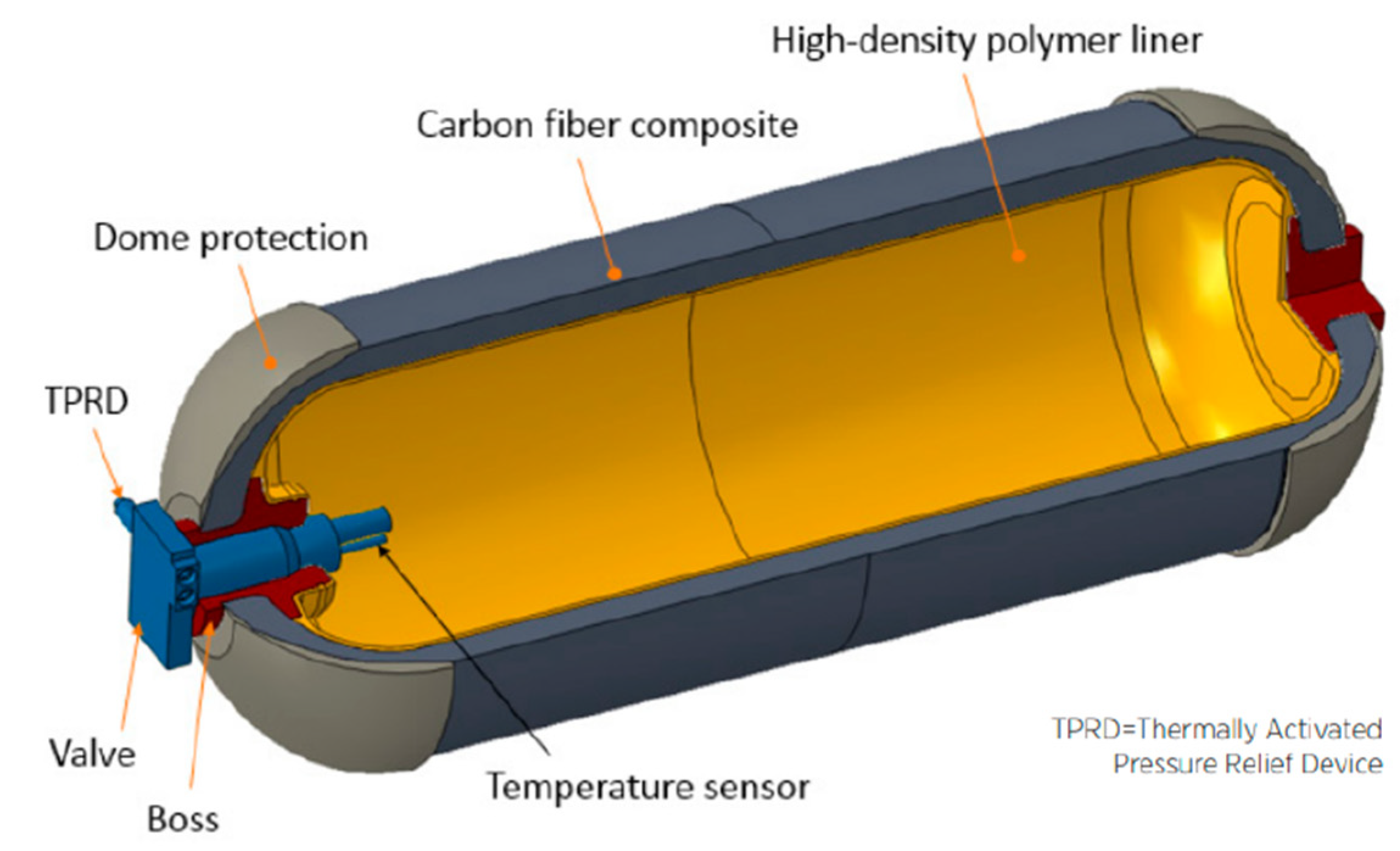
The Type IV storage vessel has become the preferred option for FCEV manufacturers. As mentioned, it primarily comprises three layers of materials designed to withstand severe internal and external loading conditions. The inner layers consist of a high-density polyethylene (HDPE) liner that serves as a hydrogen barrier and provides the shell for overwrapping the outer layer. HDPE’s mechanical and thermal properties make it an ideal material for manufacturing Type IV tanks, as it offers thermal stability up to 120 °C, excellent chemical resistance, and toughness to the tank structure. Therefore, it is capable of maintaining its properties during a large number of charging and discharging cycles
[6][1].
Figure 81 shows a schematic representation of a Type IV vessel for the automotive industry.
Figure 81. A schematic of a Type IV composite overwrapped pressure vessel designed for compressed hydrogen storage on board FCEVs [22]. A schematic of a Type IV composite overwrapped pressure vessel designed for compressed hydrogen storage on board FCEVs [5].
The liner of a composite pressure vessel is typically fabricated using various methods such as injection, blow, compressing, and rotational molding processes. These techniques are commonly employed to manufacture hard and high-strength plastic products for commercial applications. Injection molding, in which melted plastic is injected into a mold cavity, is generally preferred for mass-producing small products. Blow molding is similar to injection molding, but the melted plastic is extruded vertically into a molten tube and cooled to form a hollow part. Rotational molding, on the other hand, involves rotating the plastic in hollow molds and cooling it with water to harden and form a hollow part
[6][1]. This technique entails the bi-axial rotation of the metallic mold in a heated oven to produce stress-free parts.
Rotational molding is a cost-effective and efficient process that produces less waste, making it an ideal choice for low-to-high-volume production. This method is particularly suitable for manufacturing hollow shapes of varying sizes, resulting in improved part-wall-thickness distribution compared to other molding processes, such as injection and extrusion molding. The outer shell of Type IV tanks is typically made of fiber-reinforced polymer with epoxy resin
[6][1].
Carbon fiber with epoxy resin is widely preferred for Type IV tanks due to its strength, flexibility, and high translation efficiency. However, the high manufacturing cost associated with carbon fiber, which contributes to approximately 62% of the total weight of the tank and has a higher per kg cost, has led to the adoption of the filament winding technique for wrapping the fiber
[6][1]. This technique is a popular method for producing symmetric composite tanks, tubes, cylinders, and domes. It involves depositing fibers in a specifically oriented pattern that matches the direction of stresses and loads in the structure.
1.2. Liquid Hydrogen Storage
Currently, compressed hydrogen is the most widely adopted hydrogen storage technology. However, its low energy density and safety concerns have motivated researchers to investigate alternative methods like liquid hydrogen. The aerospace and nuclear industries were the early adopters of liquid hydrogen due to its high energy density and purity. The development of liquid hydrogen production and storage systems was accelerated by the research and production of rocket propulsion based on liquid oxygen and liquid hydrogen during the 1930s and 1950s. As a result, industrial-scale systems were constructed to meet the increasing demand for liquid hydrogen in these sectors
[23][6].
As previously mentioned, hydrogen exhibits lower energy density per unit volume than many other fuels, translating into a need for larger storage tanks to store the same amount of energy. To address this issue, the liquefaction of hydrogen is a potential solution. Compressed hydrogen at 350 and 700 bar and 288 K has a density of 24.5 and 41.5 g/L, respectively, and heating values of 2.94 and 4.97 MJ/L. In contrast, hydrogen in liquid form at 1 and 3.5 bar and at its normal boiling point of 20 K (−253 °C) has a heating value of 8.50 and 7.68 MJ/L, respectively, and a density of 70.9 and 64.0 kg/m
3, respectively
[19][2]. Remarkably, liquid hydrogen is approximately 1.8 times denser than high-pressure hydrogen at 700 bar and 288 K, highlighting its potential advantages in energy storage and transportation
[24][7].
Aspects such as increased density over high-pressure gas storage, reduced weight and pressure of tanks, and enhanced safety considerations, have made liquid hydrogen an attractive alternative to compressed hydrogen. Although liquid hydrogen can only exist at low temperatures and pressures, the corresponding tanks can be lighter as they operate at lower pressures. Moreover, liquid hydrogen storage presents a more compact and cost-effective storage and transportation solution than compressed hydrogen
[21,25][4][8]. As a result of its higher gravimetric and volumetric density, liquid hydrogen is now widely regarded as the optimal choice for transportation and distribution, offering significant advantages in terms of economics, technical feasibility, and energy content
[23][6]. Liquid hydrogen also has several drawbacks that need to be addressed. One of the most significant issues with liquid hydrogen is the energy-intensive liquefaction process, which can consume up to 30% of the energy content of the stored hydrogen. Furthermore, to minimize boil-off, it is necessary to maintain constant pressure in the storage tank and ensure that it is well insulated. A cooling and venting system should also be in place to achieve this.
Liquid hydrogen storage has several disadvantages, one of which is the low efficiency of the liquefaction process. Around 30 to 35% of the energy value of hydrogen is consumed during the liquefaction process, which is approximately three times more than the energy required to compress hydrogen. Therefore, advancements in hydrogen liquefaction are necessary to make liquid hydrogen a viable option for hydrogen storage. Additionally, it is worth noting that liquid hydrogen storage is still an emerging technology that requires further development
[6,21,23,26][1][4][6][9].
To store hydrogen in liquid form, it is essential to maintain the hydrogen temperature below its boiling point of 20 K to avoid overpressure in the storage container. This requires precise temperature control and the implementation of cooling systems. Efficient insulation of storage tanks is also crucial to minimize the loss of hydrogen through evaporation. However, it is important to note that insulation is never perfect, and heat transfer from the environment to the tank is inevitable, increasing pressure inside the container. Given that liquid hydrogen is stored at low pressures, the pressure must be regulated to prevent overpressure, which can be achieved by venting hydrogen from the tank through a valve, a process known as “boil-off”
[22][5]. Thus, a cryogenic storage vessel with effective insulation is necessary to prevent the loss of hydrogen through venting and extend the storage time without any loss. Despite the high level of insulation in cryogenic storage vessels, “boil-off” is an inevitable phenomenon, resulting in 2 to 3% loss of hydrogen per day. This presents a significant challenge for liquid hydrogen storage, as “boil-off” cannot be entirely prevented but only minimized. The loss of hydrogen through “boil-off” impacts energy efficiency and cost and poses a safety concern, particularly in confined spaces where a hydrogen leakage may occur
[6,22,23,26][1][5][6][9].
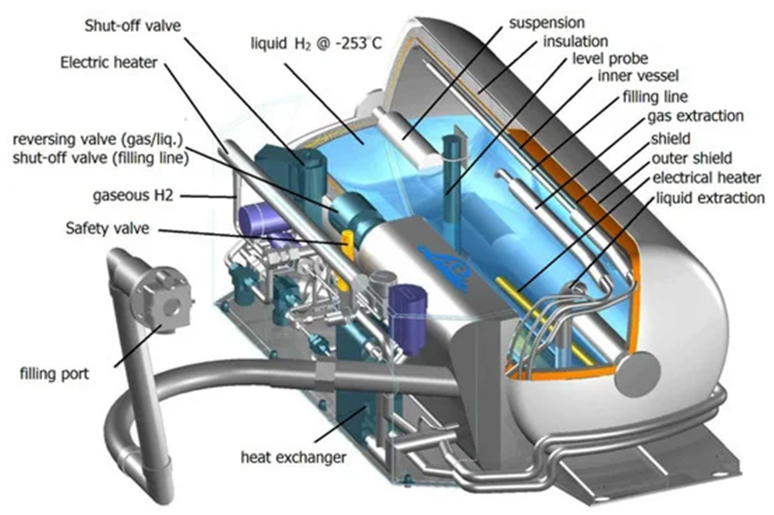
Liquid hydrogen is stored in cryogenic tanks that are cylindrical or spherical double-walled vessels, where the inner and outer walls are separated by multiple layers of vacuum to provide thermal insulation, as shown in Figure 102.
Figure 102. Scheme of the main components of a typical tank for liquid hydrogen storage [27]. Scheme of the main components of a typical tank for liquid hydrogen storage [10].
The construction of these vessels involves using specific materials to minimize conductive and radiant energy flows from the environment into the tank, along with vacuum-insulated jackets to further reduce thermal losses. These materials must possess the ability to withstand the low temperatures of liquid hydrogen, prevent hydrogen gas permeation, and resist hydrogen embrittlement. By implementing these design features, modern large-scale cryogenic tanks can effectively mitigate the “boil-off” effect, reducing it to as low as 0.1% per day of the total hydrogen stored
[21,23,26,27][4][6][9][10]. The “boil-off” rate of liquid hydrogen is influenced not only by the thermal insulation of the tank but also by the size and shape of the vessel. Larger tanks are generally preferred, requiring a smaller proportion of insulation mass and volume than smaller tanks. Tank shape is also an essential factor, as a reduced surface area of the liquid can minimize the heat flow from the surroundings into the liquid. Cylindrical or spherical shapes are typically preferred due to their lower surface-area-to-volume ratios
[21,22][4][5].
Cryogenic storage operates at low working pressures, which presents opportunities to utilize novel materials that can reduce the tank’s weight and improve other performance characteristics. This could result in tanks with similar specific energy storage quantities as conventional fuel tanks. In addition to these performance benefits, using new materials and design features can also improve environmental conditions and safety, while minimizing costs by selecting cost-effective materials and processes
[28][11]. Regarding insulation, two main types are commonly employed. The first one is the vacuum-jacketed system. This method involves using multiple layers of a low-emissivity and high-reflectivity material separated by thin fiberglass sheets. The outer container is designed to maintain a low pressure, which results in excellent insulation. However, a main drawback of this method is that the system can fail if the vacuum is lost, resulting in a significant waste of liquid hydrogen through “boil-off”. The second option is to apply rigid closed-cell foam insulation to the tank’s exterior. While this method may exhibit a higher density and thermal conductivity, it can still be a viable choice depending on the specific application
[29][12].
Liquid hydrogen storage systems are particularly appealing for flight and space applications and large-scale hydrogen transportation and delivery. This is due to their high volumetric and gravimetric energy storage densities, making them attractive to these sectors. The short-term utilization of hydrogen and the fact that high-power consumption or cost are not major concerns further increase the appeal of liquid hydrogen storage systems in mobility. Trailers and ships have already been employed for liquid hydrogen distribution, with ongoing efforts to enhance transport capacity.
Achieving successful liquid hydrogen storage relies on several factors, including improving insulation to minimize “boil-off,” designing efficient cryogenic tanks, and optimizing the liquefaction process. However, a significant challenge today and in the near future is the lack of infrastructure for producing and storing liquid hydrogen. Significant developments in hydrogen infrastructure are necessary to realize a hydrogen-based mobility system. Additionally, managing cryogenic liquids requires implementing safety measures and technologies not widely used today
[23][6].
1.3. Cryo-Compressed Hydrogen Storage
Cryo-compressed hydrogen storage has become an exciting option to take advantage of the main characteristics of compressed and liquid hydrogen storage principles. This method allows hydrogen to be stored at elevated pressures above ambient (1 bar) and at temperatures equivalent to or lower than its boiling point (−233 °C). Compressing hydrogen to 350 bar at −233 °C can increase its gravimetric and volumetric density from 70 g/L at 1 bar to 90 g/L, resulting in higher storage efficiency
[6,26][1][9]. This approach results in a higher energy storage capacity per unit volume, mitigating issues such as the demand for high pressures and volumes in compressed hydrogen storage, as well as boil-off losses associated with liquid hydrogen storage.
As previously discussed, the on-board application of cryo-compressed hydrogen can be accomplished using Type III or Type IV vessels. However, due to the lower operating pressures of cryo-compressed hydrogen storage (typically 300 bar) compared to compressed hydrogen storage (700 bar), the requirement for more costly carbon fiber composites may be reduced, making Type III vessels a preferred option for this storage approach
[21][4]. The vessel used for cryogenic hydrogen storage must be designed to withstand extreme conditions of low temperature and high pressure, ensuring effective containment of the cryogenic fluid. This allows the storage system to be fueled with various hydrogen storage methods, including liquid hydrogen (LH
2), cold-compressed hydrogen, ambient-temperature compressed hydrogen, or cryo-compressed hydrogen. This versatility gives the cryo-compressed storage system a significant advantage over other storage techniques
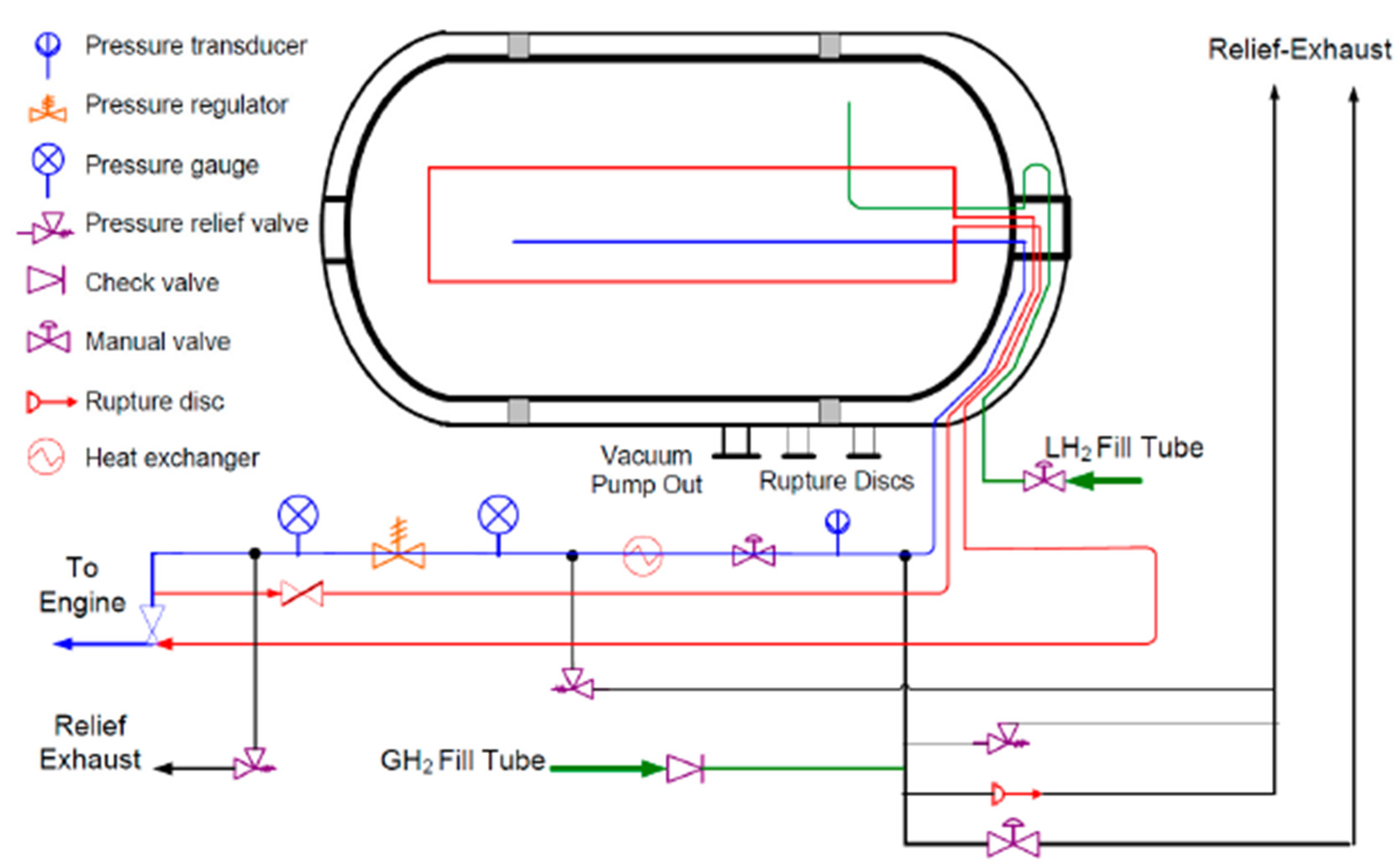
[22,23][5][6]. The Lawrence Livermore National Laboratory researchers have developed an illustrative model of a cryo-compressed storage tank, as depicted in
Figure 113.
Figure 113.
Type III cryo-compressed H
2 storage tank schematic representation [22]. storage tank schematic representation [5].
The tank comprises an inner high-pressure vessel with a metallic liner serving as a barrier between the composite overwrap and the hydrogen, thereby preventing gas leakages. The metallic liner is then wrapped in a carbon-fiber-coated metal, creating a robust outer layer. Additionally, the tank comprises a vacuum space lined with multiple layers of highly reflective metalized plastic, which functions as high-performance thermal insulation. Finally, a metallic outer jacket is included to limit heat transfer between the stored hydrogen and the surrounding environment
[20,30][3][13].
Ensuring safety during the storage and consumption of hydrogen is of paramount importance, particularly for on-board applications. While cryo-compressed hydrogen storage offers several safety advantages over liquid and compressed hydrogen storage techniques, the physical damage to the cryo-pressured vessel due to a vehicular accident remains a potential risk. Such an event could lead to the sudden expansion of cryo-compressed hydrogen to atmospheric pressure.
Hydrogen can exist in two different forms based on the orientation of its nuclear spin: para-H
2 and ortho-H
2. At very low temperatures, around 20 K, hydrogen is primarily in the para-H
2 state, which is the low-energy form and stable under these conditions. However, as the temperature increases from 20 K to room temperature, the equilibrium shifts towards the ortho-H
2 state
[31][14].
The results indicate that the maximum mechanical energy release occurs at almost ambient temperature (300 K) with a value of 0.6 kWh/kgH
2 at 300 bar, and this maximum release remains relatively constant with increasing pressure. In contrast, temperature strongly influences the theoretical maximum mechanical energy. Specifically, at a pressure of 300 bar, the maximum mechanical energy release is significantly reduced by almost 92% (0.05 kWh/kgH
2) at a temperature of 60 K. These findings suggest that cryo-compressed hydrogen storage may be a safer option, as the potential damage of a sudden rupture is reduced at lower temperatures
[31][14].
The combination of the low burst energy and high hydrogen storage density at cryogenic temperatures presents a suitable solution for developing smaller tanks that can withstand automotive collisions. Furthermore, as previously noted, the cryo-compressed vessel is designed with various layers that offer an expansion volume that permits sudden release at a significantly reduced pressure. The low energy content of cold hydrogen, along with the effective dissipation power mitigation, can produce highly secure systems that cause minimal damage, even in the event of abrupt failure.
Cryo-compressed hydrogen storage technology can fill the storage tank with compressed, cryo-compressed, or liquid hydrogen, presenting several advantages over other hydrogen storage methods, including a greater storage capacity and enhanced safety indicators. Despite these benefits, cryo-compressed tanks are not yet commercially feasible due to the availability of infrastructure and the cost associated with this storage technique.
Table 42 comprehensively summarizes the various types of physical hydrogen storage methods for on-board vehicle applications. It presents key information such as the type of vessel used, operating pressure and temperature, application, as well as their respective advantages and disadvantages. This table offers a convenient overview of the different storage options, aiding in understanding and comparing the characteristics of compressed H2 storage, liquid H2 storage, and cryo-compressed H2 storage for on-board vehicle applications.
Table 42.
Comparison of physical hydrogen storage methods for on-board vehicle applications.
1.4. Safety Standards for On-Board Applications
Compressed hydrogen storage for on-board vehicle applications combines robustness and safety advantages. Hydrogen tanks are engineered to withstand high pressures, undergo rigorous testing, and adhere to stringent safety standards, ensuring the system’s integrity and durability. To make sure that FCEVs are safe, there are international standards that define certain requirements. These standards have specific criteria for hydrogen storage systems.
One of these is the GTR 13 standard. It establishes that the hydrogen permeation rate of the compressed hydrogen storage system should be less than 46 N cm
3 h
−1 L
−1 under specific operating conditions: the system should be tested at 1.15 times the nominal working pressure (NWP) and a temperature of 55 °C. Another safety standard that applies to the hydrogen storage tanks in the system is ISO 19881: 2018; Gaseous hydrogen—Land vehicle fuel containers; ISO
®: Geneva, Switzerland. Available online:
https://www.iso.org/standard/65029.html (accessed on 28 June 2023). According to ISO 19881, the steady-state permeability of Type IV hydrogen storage tanks should be less than 6 N cm
3 h
−1 L
−1 at the nominal working pressure (NWP) and the ambient temperature (293 K)
[32][15]. Moreover, the lighter-than-air nature of hydrogen minimizes the risk of fire or explosion in the event of a leak, as it quickly disperses instead of pooling on the ground like gasoline. Advanced safety features like pressure relief devices and rupture discs further prevent over-pressurization and enable controlled hydrogen release during emergencies, enhancing overall safety.
For that reason, equipping FCEV tanks with safety valves and pressure relief devices is essential to prevent overpressurization. These devices release excess pressure in the event of an anomaly, preventing potential tank ruptures. Regular maintenance and inspection of these valves are crucial to ensure safety standards.
1.5. Underground Hydrogen Storage
Natural underground formations, including aquifers, depleted natural gas fields, and artificial caverns, such as salt caverns, present a potential solution for hydrogen storage. Aquifers are particularly attractive due to their water-bearing permeable rock or sand layers that can trap hydrogen injected at high pressure. In addition to aquifers, hydrogen can also be stored in the porous rock found in natural gas caverns
[33][16]. These hydrocarbon reservoirs, located deep beneath the subsurface, are known for their porous and permeable nature because most recoverable products have already been extracted. Depleted hydrocarbon reservoirs have a history of success as gas storage options, as they are known for storing hydrocarbons, such as natural gas, and have well-established geological structures. Despite this, there is a potential risk to the purity of injected gas if the remaining gas in the reservoir is not properly managed, affecting the integrity of the stored hydrogen
[34,35][17][18].
On the other hand, salt caverns offer secure and stable underground storage facilities for various materials, including oil, natural gas, and hydrogen. Formed by dissolving salt formations by injecting fresh water under high pressure, salt caverns are typically found in underground salt domes. The pressure inside a salt cavern is critical and needs to be carefully monitored as it is affected by the amount of gas stored within it. With appropriate management, salt caverns provide a reliable and safe way to store hydrogen underground over extended periods
[35][18]. A typical salt cavern can be up to 2000 m deep, 1,000,000 m
3 in volume, 300 to 500 m in height, and 50 to 100 m in diameter, allowing for vast hydrogen storage
[34][17].
These underground formations could provide a secure and cost-effective option for large-scale hydrogen storage, enabling its integration with intermittent renewable energy sources and decarbonizing various sectors, including transportation, heating, and power generation.
2. Chemical Storage
Currently, major automotive manufacturers prioritize on-board compressed hydrogen gas storage (at 700 bar) due to its fast-refueling capability (within <3 min) and its established technological maturity. However, to overcome the limitations of the physical storage methods, solid-state hydrogen storage could play an important role due to its potential advantage of offering higher volumetric densities. To achieve higher hydrogen storage density with compactness, researchers are currently exploring the potential of solid materials that can physically absorb or chemically react with the gas. Another relevant way to store hydrogen is using absorption or adsorption processes via two different mechanisms known as chemisorption and physisorption, which allow H
2 to bind to the surface of a specific material. Physisorption involves weak molecular hydrogen bonding to the surface material with weak Van der Waal forces. In contrast, chemisorption involves dissociating H
2 molecules into H atoms and their subsequent migration to the material to occupy the interstitial site to form new and strong chemical bonds
[36][19].
Chemical hydrogen storage has been found to have some advantages over other methods. One of the most notable advantages is its better volumetric densities, which is crucial for on-board applications. However, chemical hydrogen storage poses challenges and drawbacks, such as slow kinetics, low gravimetric densities, low reversibility, and high dehydrogenation temperatures or pressures. Despite these limitations, studies and efforts are being made to improve different chemical hydrogen storage solutions for specific applications. One way to address reaction constraints is through the use of catalysts, which can enhance kinetics and thermodynamic stability for a metal hydride. It is important to note that, while catalysts can improve storage efficiency, they do not absorb hydrogen and can potentially reduce storage capacity by occupying space previously intended for hydrogen
[37][20]. For material-based technologies to be suitable for on-board hydrogen storage, they must possess certain key characteristics. These may include high hydrogen storage capacity, rapid charging and discharging capabilities, good reversibility, stability over multiple hydrogen uptake and release cycles, and rapid kinetic properties.
Chemical hydrogen storage relies on a storage carrier that, under certain conditions of temperature and pressure, can absorb or react with hydrogen (hydrogenation) to form a stable compound that is stable under atmospheric conditions. Upon demand, the hydrogen can be released (dehydrogenation) by altering the pressure and temperature conditions. Various chemical methods are available for hydrogen storage, including metal hydrides such as intermetallic compounds, complex hydrides, chemical hydrides, liquid organic hydrogen carriers, and nanostructures. However, these storage techniques are currently in their early research stages and are not technically and economically feasible for automotive applications
[37][20].