Integrating renewable energy through inverter-based generators has decreased the power system’s inertia. Reduced inertia may lead to frequency instability during power imbalance disturbances, particularly in an isolated power system with limited inertia. The Battery Energy Storage System (BESS) and a virtual inertia (VI) emulation control system have become popular to mitigate this issue. Nonetheless, the BESS utilization for VI emulation is highly dependent on the availability of BESS capacity, which may affect the energy cost. Therefore, developing a VI emulation control strategy that requires less energy and can recover the state of charge (SoC) to a desired level to optimize BESS utilization is required. This paper proposes a VI control with an SoC recovery strategy through coordination with the generators’ secondary frequency control. Instead of relying on the frequency, such as in the conventional approach, the controlled signal of the generators’ secondary frequency control also includes the VI power and BESS SoC. Hence, the generators can contribute to lowering the VI required energy and recovering the BESS SoC. The results show that the proposed method outperforms the conventional method by requiring around 36% lower energy and the ability to maintain the BESS SoC.
1. Introduction
Integrating renewable energy sources into the grid through power electronic coupling, such as inverters, may reduce inertial capacity and lower the performance in responding to a supply–demand imbalance that occurs in the electric power system, which conventionally can be handled by a synchronous generator. This imbalance will affect the systems’ frequency characteristics, such as more deviation of nadir frequency, steeper rate of change of frequency (RoCoF), more diversion of steady-state frequency, or even longer frequency settling time. These characteristics may trigger the protection scheme and cause a system blackout.
The inverter-based generation is predicted to exceed the number of rotational-based generations in the future. Besides, when the microgrid system is implemented on large grids in the future, the same challenges will also arise when the microgrid must operate in an islanded mode. Hence, the microgrids are required to operate the electric power system independently, including supply and load balancing, voltage and frequency control, and power quality control. In fact, the generation capacity and its reserves will be limited when the microgrid is separated from the main grid, and the dominance of inverter-based generators will also reduce the inertial capacity of the microgrid system. These conditions will cause the system inertia to decrease and may lead to system instability during disturbances. Therefore, it is necessary to develop various methods and strategies to minimize the negative impact of inverter-based renewable power generation to maximize their integration into the power system. Specifically, such methods and strategies are highly required for isolated grids or islanded-mode microgrids with low inertia due to the increasing penetration of inverter-based renewable energy generations.
The Battery Energy Storage System (BESS) has been widely used to overcome the frequency instability challenges arising from a supply–demand imbalance in a low inertia power grid. The utilization of BESS for frequency regulation must consider both technical and economic aspects. BESS is still costly, and the ancillary service market for frequency regulation to enable the return of BESS investment is not fully deployed in many countries. Thus, in the case of small and isolated grids, the required BESS investment might not be considered economically feasible. Therefore, this research aims to propose a frequency control strategy that can operate with a lower BESS capacity without neglecting its performance through BESS state-of-charge (SoC) recovery.
2. Coordinated Virtual Inertia Control Strategy
The VI control works by emulating the required power during disturbances, and it has the operational characteristics shown in
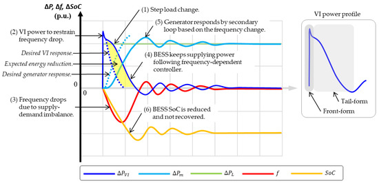
Figure 51. First, when a disturbance occurs (modeled as step load change) in an isolated system, the VI will quickly respond to that change by providing almost instantaneous power to restrain the frequency drop. The VI will continue to supply power to the system based on the frequency change. Similarly, the generator will start responding, which is controlled by its secondary frequency loop. The steady-state frequency can be achieved after several minutes, depending on the value of the secondary frequency gain. Hence, both VI emulation and the generator’s secondary frequency control perform based on the frequency (frequency-dependent). In addition, the BESS SoC will be reduced, because it discharges power to the system and will not be recovered solely by the existing control strategy.
Figure 51. Illustration of VI operation characteristics showing the VI power, generator’s power, frequency, and the BESS SoC. The generator and VI are operating based on the system’s frequency profile. Generally, the VI power profile can be divided into front-form and tail-form.
In
Figure 51, the profile of VI power can be divided into front-form and tail-form. Front-form is associated with the required power to improve the frequency during disturbances, which is the expected operating performance from a VI emulation. Meanwhile, the tail-form is the additional power that follows the frequency-dependent controller. At the beginning of a disturbance, the VI front-form causes a lower frequency deviation that slows down the generator’s secondary control response. The VI tail-form may not be necessary because the generator can manage the power imbalance. Therefore, a proper control strategy can modify the behavior of VI and the generator’s secondary control such that the VI only participates at the beginning of a disturbance and charges/discharges power as minimum as possible in the tail-form period to give the generator a chance to increase/decrease the power. By doing this, the BESS capacity can be optimized, as shown in yellow in
Figure 51.
This rResearch
ers propose
s a control strategy that coordinates the secondary frequency control operation with the virtual inertia control. Hence, the secondary frequency control, or LFC, is forced to supply the power with the virtual inertia and manage the BESS SoC. The LFC sets the generator output power to manage the power delivered/absorbed by BESS. By doing this, the virtual inertia emulation system will only be responsible for a shorter period right after disturbance (front-form), requiring less energy. Consecutively, the LFC will balance the supply and demand while suppressing the power from BESS and even recovering the BESS SoC.
The conventional VI and generator’s secondary frequency control are frequency-dependent. It means that the output power of VI and the generator will be determined by the frequency and the controller’s parameters. The proposed strategy i
n this
research is to incorporate additional controlled signals to the secondary loop to coordinate with the VI performance. These additional controlled signals are the VI power and the BESS SoC. The VI power and BESS SoC are fed to adjust the reference setting of the generator’s secondary control. Hence, the generator’s response will depend not only on the frequency but also on the VI performance and the BESS SoC. Moreover, the BESS SoC signal will instruct the generator to recover the SoC to the nominal value.
The transfer function formulation for coordinated strategy considers the amount of virtual inertia power and the required virtual inertia energy. This strategy will modify the control signal that is conventionally and solely based on the frequency value. Originally, the reference setting (
Δ𝑃𝐶) obtained from the LFC is defined as follows:

and by incorporating the control signal from the primary frequency control (droop setting), the generator will generate the required power to stabilize the supply and demand, thus the frequency. The additional controlled signals, namely, the VI power (
Δ𝑃𝑉𝐼) and BESS SoC (
Δ𝑆𝑜𝐶), are added to determine the reference value, as follows:

where
Δ𝑃∗𝐶 is the modified reference signal of the generator, taking into account the VI power and BESS SoC, and
Κ𝑄 and
Κ𝑅 are the controller’s parameters. Hence, the controller’s parameter,
Κ𝑄 and
Κ𝑅, can be developed by using various control algorithms, such as Proportional–Integral–Derivative (PID) or proportional–integral (PI) controller, fuzzy logic, or MPC.
This paper uses a PI controller to provide an understanding of the proposed strategy.
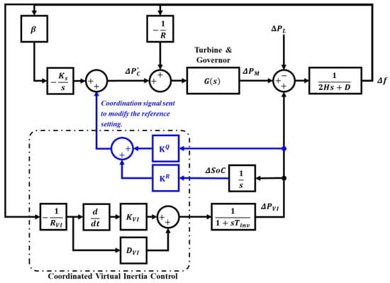
The control block diagram of the coordinated virtual inertia control–secondary frequency control is shown in
Figure 62. The generated virtual inertia power signal and the BESS SoC status are fed back and processed to adjust the reference setting of the secondary frequency control. The control parameters,
Κ𝑄 and
Κ𝑅, are utilized to modify the behavior of the virtual inertia power supplied by BESS. This method allows BESS through VI control to only provide the necessary inertia power for a shorter period (front-form), either by discharging or charging the power, and the generators will continue to manage the system’s required power so that VI’s contribution will be minimized, and the energy capacity can be reduced. Besides, the generator will also increase or decrease power at the steady-state period for SoC recovery operation. The selection of the control parameters determines the amount of energy reduction from BESS for VI service and the period of SoC recovery after the disturbance.
Figure 62. Coordinated virtual inertia control–secondary frequency control. A control signal is sent to adjust the reference power setting of the secondary frequency control (Δ𝑃∗𝐶) based on the frequency change (Δ𝑓), VI power (Δ𝑃𝑉𝐼), and BESS SoC (Δ𝑆𝑜𝐶). Κ𝑄 and Κ𝑅 are the coordinated control parameters that optimize VI power and the BESS capacity.
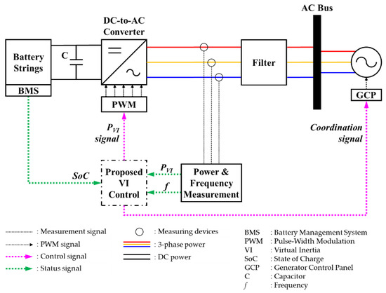
The VI emulation system configuration with the respected power electronics converter is presented in
Figure 73. The system consists of the BESS as an energy provider completed with the DC-to-AC converter with Pulse-Width Modulation (PWM) control. The PWM control receives the signal from the proposed VI control to determine the required amount of VI power to deliver or absorb. The VI control also sends a coordination signal to the Generator Control Panel (GCP) to determine the modified reference setting of the secondary frequency control of the generators. In addition, the VI control receives the input signal, such as the BESS SoC, the output power of the converter (VI power), and the system’s frequency.
Figure 73. Configuration of the proposed VI control with power electronics converter. The proposed VI control inputs are the converter (𝑃𝑉𝐼) output power, the system frequency (f), and the BESS SoC. The outputs are the signal sent to the converter’s PWM to instruct the amount of power to deliver/absorb and the coordination signal sent to the generator control panel (GCP) to instruct the required power from the generator.