Your browser does not fully support modern features. Please upgrade for a smoother experience.
Please note this is a comparison between Version 1 by Chamila Gunathilake and Version 3 by Rita Xu.
As the primary greenhouse gas, CO2 emission has noticeably increased over the past decades resulting in global warming and climate change. Surprisingly, anthropogenic activities have increased atmospheric CO2 by 50% in less than 200 years, causing more frequent and severe rainfall, snowstorms, flash floods, droughts, heat waves, and rising sea levels in recent times. Hence, reducing the excess CO2 in the atmosphere is imperative to keep the global average temperature rise below 2 °C.
- CO2 capture technologies
- CO2 adsorption
- porous silica
- Chemisorption
- Physisorption
- Greenhouse Gases
1. Introduction
With the exponential growth of industrialization, global warming and climate change have become worldwide concerns and have attracted much attention in recent decades [1]. Furthermore, human activities have significantly contributed to the increased levels of CO2 in the atmosphere. For example, atmospheric CO2 measured at NOAA’s Mauna Loa Atmospheric Baseline Observatory peaked for 2021 at a monthly average of 419 parts per million (ppm), and it is reported as the highest level since accurate measurements began 63 years ago [2].
The increase in CO2 concentration leads to the rise in global temperature and sea levels, alternative of rainfall patterns, extinction of species, natural disasters such as severe weather events, ranging from flash floods, hurricanes, freezing winters, severe droughts, heat waves, urban smog, and cold streaks [3].
The main CO2 stationary emission sources are power plants, refineries, chemical and petrochemical, iron and steel, gas processing, and cement industries. More irreversible and adverse environmental impacts should be expected if atmospheric carbon dioxide continues to rise. Therefore, the international communities led by the United Nations reached a landmark global accord, the Paris Agreement, adopted by 196 nations in 2015 to address climate change and related issues. Moreover, countries around the globe made their “nationally determined contributions (NDCs)” of greenhouse gas reduction.
2. CO2 Capture
2.1. CO2 Capture Technologies
Capture and sequestration of CO2 (CCS) from aforementioned stationary emission sources has been identified as a paramount option for the issues of global warming and climate change. CCS includes four primary steps known as CO2 capture, compression, transport, and storage, therefore, developing an efficient and economically feasible technology for the capture and sequestration of CO2 produced by anthropogenic emissions is critically important. CO2 capture is the central part of the CCS technology process and gained around 70–80% of the total expensive. However, CSS methods can be classified as, for example, (i) Post-combustion (ii) Pre-combustion, and (iii) Oxy-fuel combustion (Oxygen-fired combustion) [4][5][5,6]. In post-combustion capture technology, it collects and separates the CO2 from the emission gases of a combustion system [6][7][8][9][10][7,8,9,10,11]. Firstly, flue gas (mainly consists of CO2, H2O, and N2) passes through denitrification and desulphurization treatments. As the next step, the flue gas is fed to an absorber which contains solvent. Herein, CO2 regeneration occurs. Then the CO2-rich absorbent is sent to a CO2-stripper unit to release the CO2 gas. Moreover, CO2-lean absorbent is sent back to the CO2-absorber unit [1]. Next, the captured CO2 is then compressed into supercritical fluid and then transported [1] as shown in Figure 1.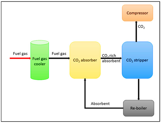
Figure 1. Schematic representation of post-combustion technology.
2.2. Criteria for Selecting CO2 Sorbent Material
Certain economical and technical properties are required in order to select the best solid adsorbent candidate for a particular CO2 capture application. These criteria are listed and described below.-
Adsorption capacity for CO2:
-
Selectivity for CO2:
-
Adsorption and desorption kinetics:
-
Mechanical strength of sorbent particles:
-
Chemical stability/tolerance towards impurities:
-
Regeneration of sorbents:
-
Sorbent costs:
2.3. Liquid Amine for CO2 Capture
Development of solvents for CO2 chemical absorption is a major area of research [19][27]. The ideal solvent should have a high CO2 absorption capacity and react rapidly and reversibly with CO2 with minimal heat requirement. The solvent should exhibit the following properties such as stability in oxidative and thermal environment, low vapor pressure, toxicity, flammability, and reasonable production cost [19][27]. Recently, a most promising CO2 capture method with chemical absorption is by using liquid amine which can be divided mainly into two groups known as simple alkanolamines and sterically hindered amines [20][28]. Examples for simple alkanolamines are monoethanolamine (MEA), diethanolamine (DEA), and triethanolamine (TEA) [21][22][29,30]. Furthermore, alkanolamines are the most widely used sorbents for CO2 capture. The structures of alkanolamines include primary, secondary, ternary amines containing at least one hydroxyl (-OH) group and amine group-(N-R). However, these different amine classes have different reaction kinetics with CO2, CO2 absorption capacity and equilibria, stability, and corrosion [20][28]. As shown in Equations (1) and (2) below, both primary and secondary amines react with CO2 to form a carbamate and protonated amine, consuming approximately two moles of amine per mole of CO2 according to the zwitterion mechanism [23][31]. According to Equation (3), tertiary amines react with CO2 gas molecules in the presence of H2O while forming bicarbonates.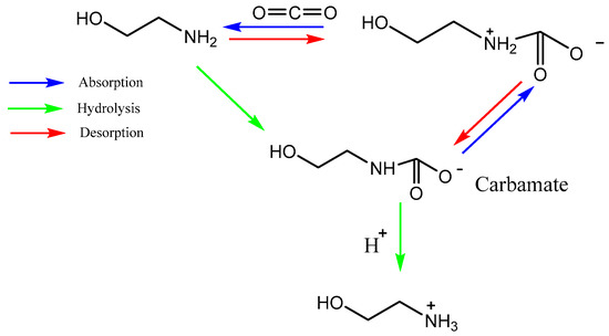
Figure 2. Reaction mechanism of CO2 capture into MEA solution.
There are three categories of alkanolamines that show increased capital costs due to requirement of specialized and expensive materials for construction [20][28]. On the contrary, degradation of alkanolamine causes operational, and environmental problems including high amount of absorbent required, corrosion of equipment, and demanding of energy [16][24].
Among three different alkanolamines, MEA is commonly considered as a well-established solvent to separate CO2 because it can be regenerated easily [25][35]. On the other hand, Rinprasertmeechai et al. reported the order of CO2 absorption capacity of the different alkanolamines as MEA > DEA > TEA [26][33]. Moreover, they have further showed the regeneration ability of the amines in the following order: MEEA > > DEA > MEA. MEA exhibits high CO2 adsorption capacity as it reacts more rapidly with CO2 compared to MEDA by forming carbamates. However, MEDA shows high regeneration efficiency and requires lower energy [27][36]. Moreover, Wang et al. found that, when MEA and MEDA are mixed with the appropriate ratio, the energy consumption for CO2 regeneration is reduced significantly [28][37].
Sterically hindered amines are based on primary or secondary amines with bulky alkyl groups, which is inhibited from reacting with CO2 through the effect of steric hindrance [20][28]. One example of sterically hindered amines is 2-amino-2-methyl-1-propanol (AMP). Steric factor reduces the stability of the formed carbamate due to the weak interaction between the CO2 molecule and the NH2 group, promoting fast hydrolysis to form bicarbonate and reducing regeneration energy. Due to the immediate regeneration process of AMP, the NH2 group can react with CO2 molecules over and over, increasing CO2 adsorption. Moreover, Dave et al. [29][38] compared the CO2 absorption of different liquid amine classes and showed a lower regeneration energy requirement for 30 wt% AMP over 30% MEA, 30% MEDA, 2.5% NH3, and 5% NH3 [29][38].
Recently, ionic liquids (IL) have also been investigated as liquid solvents for CO2 capture due to their low vapor pressure, thermal stability, non-toxicity, and adsorption capacity [30][31][32][39,40,41]. The widely studied ILs include bis(trifluoromethylsulfonyl)imide (TF2N), tetrafluoroborate (BF4), and hexafluorophosphate (PF6) [30][31][32][39,40,41]. However, the main drawbacks of the ILs are high viscosity and production high cost.
2.4. Comparison between Major Non-Carbonaceous Solid Sorbents for CO2 Capture and Importance of Silica Materials
Due to the low contact area between gas and liquid, low CO2 loading, and absorbent corrosion associated with liquid amine-based sorbents, solid sorbents for CO2 capture have attracted significant attention in recent years [33][34][42,43]. Various solid adsorbents have been proposed according to their structures and compositions, adsorption mechanisms, and regeneration process [34][43]. Many solid sorbents are cheap and readily available and show low heat capacities, fast adsorption kinetics, high CO2 adsorption capacities and selectivity, and high thermal, chemical, and mechanical stabilities [34][43].
Commercially available solid adsorbents for CO2 capture include carbonaceous materials such as activated carbons, nanofibrillated cellulose (CFCs), carbon nanotubes (CNTs), and non-carbonaceous materials, including silica, zeolites, hollow fibers, and alumina [5][6]. These materials show different surface morphologies, pore structures, specific surface areas, and functional groups.
Carbonaceous adsorbents are widely used for CO2 capture due to their relative abundance, low cost, renewability, and high thermal stability. However, the weak CO2 adsorption capacities of carbonaceous materials at 50–120 °C make it challenging to use in industrial CO2 capture [35][44]. Therefore, much research focus has been given to non-carbonaceous materials.
Zeolites are aluminosilicates with ordered three-dimensional (3D) microporous structures with high crystallinity and surface area [35][44]. The adsorption efficiencies of zeolites are primarily affected by their size, charge density, and chemical composition of cations in their porous structures [28][37]. It has been reported that the CO2 adsorption of zeolites increases as the Si/Al ratio increases and is exchanged with alkali and alkaline-earth cations in the structure of zeolites [36][45]. However, zeolites present several drawbacks, such as relatively low CO2/N2 selectivity and high hydrophilicity [37][46]. Apart from the above, zeolites show reduced CO2 adsorption capacity when CO2/N2 mixtures contain moisture, and zeolites require high temperatures (>300 °C) for regeneration [38][47].
Recently, metal-organic frameworks (MOFs) have gained much attention owing to their unique properties, such as tunable pore structure and high surface area [39][48]. However, when exposed to gas mixtures, the MOFs show decreased adsorption capacities [37][46]. Moreover, previous reports indicate that MOFs are promising materials for CO2 capture in laboratory settings; however, further research is required to confirm their practical applicability [40][49]. Water vapor also negatively affects the application of these sorbents by competing and adsorbing them onto physisorbents, thus decreasing their CO2 adsorption capacity [41][50].
Ordered mesoporous silica materials are good candidates because of their high surface area, high pore volume, tunable pore size, and good thermal and mechanical stability. So far, mesoporous silica includes the families of MCM (Mobil Company Matter: M41S, Santa Barbara Amorphous type material (SBA-n), anionic surfactant-template mesoporous silica (AMS) [35][44]. However, the CO2 adsorption capacities of them observed at atmospheric pressure are not high. Therefore, many studies have been recently reported on the functionalized mesoporous and nanoporous silica for efficient CO2 capture [42][43][51,52].
Many experimental factors control hydrolysis, silica condensation rate, assembly kinetics, nucleation, and growth rates [48][61][65,78]. The pH is an essential factor that influences the charges of silica species. Rates of hydrolysis of silane and condensation of the siloxane bond depend strongly on the charge states. Hydrolysis of the Si–OR bond in silanes could be catalyzed by acid and base conditions, but its rate is prolonged near the neutral conditions [61][78].
Sakamoto et al. [62][79] prepared silica nanoparticles (NPs) via the evaporation and self-assembly of silicate and quaternarytrialkylmethylammonium as a surfactant. This study shows that the size of NPs depends on the ratio between the surfactant and silica precursor. Apart from that, Sihler et al. [63][80] used dye-stabilized emulsion to synthesize SiO2 NPs. Moreover, this synthesis method provides silica capsules and sub-particles with precise size control. Monodispersed colloidal silica NPs (diameter of 15–25 nm) were prepared by Murray et al. [64][81]. AIn this study, as the silica source, octadecyltrimethoxysilane (OTMS) was used.
Simple synthesis methods called soft and hard templating are also applied to increase the pore volume and loading capacity of prepared hollow mesoporous SiO2 [65][82]. Template synthesis of mesoporous materials typically enrolls in three steps: template preparation, template-directed synthesis of the target materials using sol-gel, precipitation, hydrothermal synthesis, and template removal [66][67][83,84].
The hard-templating method involves nano-casting using pre-synthesized mesoporous solids [68][85]. Hard templating is a facile synthesis method for fabricating porous materials with a stable porous structure. The structure replication is very straightforward [66][83]. This approach utilizes porous hard templates such as mesoporous silica. The pores of these templates are impregnated with a precursor compound for the desired product, which is then thermally converted into the product. The template is finally removed to yield the desired mesoporous material as a negative structural replica of the hard template [66][83]. However, the method is costly and time-consuming. Moreover, the mesoporous parameters, such as mesostructure and pore sizes, are difficult to change [67][84].
In contrast, soft templating methods use cationic and anionic surfactants or block copolymers as templates [61][78]. During the synthesis, surfactant or block copolymers are used as a soft template. Moreover, the increase in surfactant micelle concentration causes the formation of a large assembly or self-assembly of 3D mesoporous [22][30]. Different 3D micelle structures can be obtained by varying the solvent ratio between the aqueous and non-aqueous and adding co-solvents. Moreover, the silica source interacts with the structure-directing agent (SDA) without any phase separation. The interactions between ions or charged molecules are vital in forming well-defined porous nanostructures [68][85].
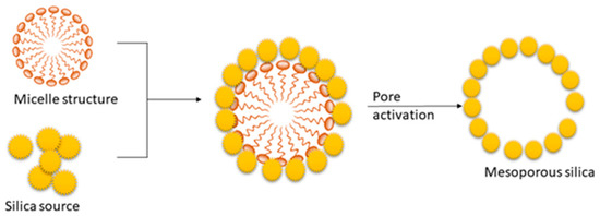
The soft templating method mainly depends on the self-assembly of the surfactant [66][83]. The process is based on the interactions between inorganics. The mesoporous structure of the final material is obtained after the removal of the pore-templating surfactant or block copolymers by low-temperature calcination (up to 600 °C) or by different washing techniques (extraction) [66][83]. Figure 3 represents the synthesis mechanism of mesoporous silica in the presence of a cationic surfactant. The synthesis process of mesoporous silica is carried out using TEOS as the silica source [22][30]. In this process, surfactant plays a significant role in defining the pore size and volume of silica [22][30]. Cationic surfactant forms micelle structures with water, which arranges the cationic “heads” of the surfactant molecules to the outer side. It resulted in the hydrophobic “tails” collected in the center of each micelle. As the next step, silica molecules cover the micelle surface. Finally, the surfactant is removed via calcination or extraction, and it results in porous silica [22][69][70][30,86,87].
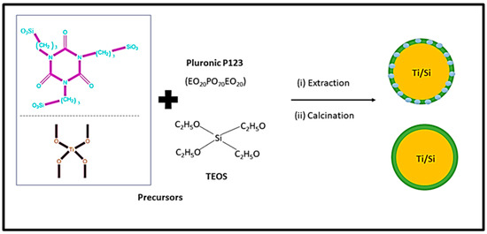
Figure 4 shows the schematic diagram for synthesizing mesoporous silica using block copolymer. As can be seen from Figure 4, titania-incorporated organosilica-mesostructures (Ti-MO) are synthesized via condensation method using silica precursors ([3-(trimethoxysilyl) propyl] isocyanurate and tetraethylorthosilicate) and titanium precursor (titanium isopropoxide) in the presence of the triblock copolymer, Pluronic P123 [71][88]. This method consists of template removal using two independent steps (i) extraction with a 95% ethanol solution and (ii) calcination of the sample at 350 °C. This method improves the adsorption capacity and enhances the structural properties such as specific surface area, micro-porosity, and pore volume.
 The synthesis of MCM-41 and SBA-15 is performed using cetrimoniumbromide (CTAB) and Pluronic P123 surfactant. The CTAB is an ionic surfactant and acts as stearidonic acid (SDA) and which causes the formation of a hexagonal array of mesostructured composites [11][12]. However, as the final step, surfactants are removed by heating in air at high temperatures or by solvent extraction to obtain MCM-41 and SBA-15 [22][30]. Wu et al. [62][79] and Hao et al. [71][88] reported a detailed description of the mechanism. Paneka and co-workers have reported the synthesis of MCM-41 from fly ash using a hydrothermal process. However, the synthesis of MCM-41 shows reduced BET surface area, increased pore volume, and pore size [72][89].
Recently, Singh and Polshettiwar [73][90] reported the synthesis of silica nano-sheets using ammonium hydroxide. They have developed a method to synthesize silica nano-sheets using lamellar micelles as soft templates in a water-cyclohexane solvent mixture. Zhang et al. [74][19] also reported the large-scale synthesis of mesoporous silica nanoparticles. Reported data show that various morphologies and particle sizes have been obtained during the synthesis. For synthesis process, the reaction occurred at atmospheric pressure with a sol–gel technique using CTAB as a template.
The synthesis of MCM-41 and SBA-15 is performed using cetrimoniumbromide (CTAB) and Pluronic P123 surfactant. The CTAB is an ionic surfactant and acts as stearidonic acid (SDA) and which causes the formation of a hexagonal array of mesostructured composites [11][12]. However, as the final step, surfactants are removed by heating in air at high temperatures or by solvent extraction to obtain MCM-41 and SBA-15 [22][30]. Wu et al. [62][79] and Hao et al. [71][88] reported a detailed description of the mechanism. Paneka and co-workers have reported the synthesis of MCM-41 from fly ash using a hydrothermal process. However, the synthesis of MCM-41 shows reduced BET surface area, increased pore volume, and pore size [72][89].
Recently, Singh and Polshettiwar [73][90] reported the synthesis of silica nano-sheets using ammonium hydroxide. They have developed a method to synthesize silica nano-sheets using lamellar micelles as soft templates in a water-cyclohexane solvent mixture. Zhang et al. [74][19] also reported the large-scale synthesis of mesoporous silica nanoparticles. Reported data show that various morphologies and particle sizes have been obtained during the synthesis. For synthesis process, the reaction occurred at atmospheric pressure with a sol–gel technique using CTAB as a template.
3. CO2 Adsorption Using Mesoporous Silica Materials (Physisorbents)
3.1. Mesoporous Silica Materials
Mesoporous silica materials are used for various applications, including catalysis and wastewater treatment [44][61]. Mesoporous silica has unique properties such as uniformity of pore distribution (with size between 0.7 and 50 nm), high surface area (around 1000 m2/g), and good thermal stability [45][62]. The first synthesized mesoporous silica material was M41S in the 1990s [46][63]. However, the development of surfactants and synthesis protocols have been able to prepare many types of mesoporous silicas such as MCM-41, SBA-15, SBA-16, FDU-2, MCM-50, and KIT-5 with a diverse range of pore geometries such as cubic, and hexagonal, and morphologies such as rods, spheres, and discs [47][64]. In 1990, Mobil Oil Corporation discovered molecular sieves of the M41S family consisting of silicate/aluminosilicate [48][65]. Typically, these materials are prepared via the sol-gel method. Three well-defined structural arrangements have been identified after studying the effect of surfactant concentration, and those are hexagonal (MCM-41), cubic (MCM-48), and lamellar (MCM-50) structures. Therefore, these materials (M41S family) exhibit mesoporous arrays with amorphous walls of about 10 Å (1 nm) [48][65]. Moreover, the structural ordering of these M41S family materials can be changed with increasing hydrothermal synthesis temperature and time [48][65]. These M41S molecular sieves are mainly applied in catalysis [49][66], adsorption [48][65], and controlled release of drugs [50][67]. The main advantage of this mesoporous silica is its unique chemical structure consisting of the high density of functional silanol groups (Si–OH), pore size and shape can be molded during the synthesis process, and the internal surface can be easily modified with organic and inorganic groups [48][51][52][65,68,69]. Santa Barbara Amorphous family (SBA) first prepared silica-based materials with well-ordered mesoporous in 1998 [48][65]. This material group consists of SBA-2 (hexagonal close-packed array), SBA-12 (three-dimensional hexagonal network), SBA-14 (cubic structure), SBA-15 (two-dimensional hexagonal), and SBA-16 (structured in a cubic cage) [48][53][65,70]. These nanostructured mesoporous materials comprise a silica-based framework with uniform and well-ordered mesopores, large pores, thick and porous walls, high surface area, and high thermal stability [52][54][69,71]. The most widely investigated members of the SBA-n family in the literature are SBA-15 and SBA-16. The SBA-15- and SBA-16-based mesoporous arrays are commonly utilized as adsorbents [52][69], catalysts or catalytic [55][72], and drug deliveries [56][73]. The Fudan University synthesized mesoporous materials family (FDU-n)-based mesoporous silica arrays with well-ordered mesostructures and pore arrangements, high surface area, large and uniform distribution of pore diameter, amorphous pore-wall structures, and thermal and mechanical stability [57][74]. FDU-1-based mesoporous materials have a 3D face-centered cubic (FCC) structure with large cage-like mesopores, while FDU-2 mesoporous array possesses a mesostructured FCC unit cell and well-ordered 3D architecture [52][69]. On the contrary, the mesoporous material series of the KIT-n family, where n = 1, 5, or 6, are mainly represented by the KIT-1, KIT-5, and KIT-6. However, KIT-1-based mesoporous silicas exhibit a 3D architecture in a disordered framework with high surface area, large pore volume and pore diameter, and thermal and hydrothermal stability [58][75]. KIT-5-based nanostructured mesoporous materials have well-ordered 3D cage-like mesopores in a face-centered close-packed cubic lattice architecture [52][69]. In addition, KIT-6 shows 3D mesoporous amorphous walls with large pore size, uniform pore distribution, high surface area, and thermal stability [52][69]. Moreover, mesoporous silica materials of the M41S, SBA-n, FDU-n, and KIT-n families are used in a wide range of applications such as separation, catalysis, drug release adsorption, sensors, matrix solid-phase dispersion (MSPD) and solid-phase extraction [52][69].3.2. Synthesis Procedures of Mesoporous Silica
Initially, Stöber et al. [59][76] discovered an effective method for synthesizing monodispersed silica particles. This process consists of hydrolysis of tetraethyl orthosilicate (TEOS) using ammonia as a catalyst in water and ethanol solution. This method leads to the synthesis of silica particles [60][77]. In this reaction, TEOS undergoes hydrolysis in an ethanol/ammonia solution. As a result, it produces silanol monomer (-Si-OH) with the epoxy groups (-Si-OEt), as shown in Equation (4). Then silanol groups undergo condensation to produce branched siloxane clusters, which causes to initiate the nucleation and growth of silica particles, see Equation (5). Simultaneously, silanol monomers react with the unhydrolyzed TEOS via condensation (see Equation (6)) and participate in the nucleation and growth of silica particles [22][30]. Moreover, the particle size of Stöber silica depends on the concentration of the aqueous ammonia solution and water in the ethanol reaction [22][30].Figure 3. Mechanism for the synthesis of mesoporous silica in the presence of a cationic surfactant.
Figure 4. Mechanism for the synthesis of mesoporous silica using block copolymer.