Your browser does not fully support modern features. Please upgrade for a smoother experience.
Please note this is a comparison between Version 2 by Catherine Yang and Version 1 by Guido Di Bella.
Friction Stir Welding is a suitable solid-state joining technology to connect dissimilar materials. To produce an effective joint, a phase of optimization is required which leads to the definition of process parameters such as pin geometry, tool rotational speed, rotation direction, welding speed, thickness of the sheets or tool tilt angle.
- FSW
- joining
- aluminum
1. Tool Shoulder and Pin Geometry
The tool used in friction stir welding is typically made of a hard, wear-resistant material such as tungsten carbide, tool steel or ceramics. It has a cylindrical shape with a shoulder at one end and a pin at the other [71][1]. The shoulder is larger in diameter than the pin and is used to apply downward force to the workpieces and to contain the material being stirred during the welding process. The pin, which is the active part of the tool, has a specially designed profile that varies depending on the material being welded and the desired welding parameters. The pin profile typically includes a threaded or fluted section that helps to mix and stir the material being welded, as well as a smooth section that creates a solid-state bond between the workpieces.
Generally, the size of the pin and shoulder of the tool determines the size of the stir zone, which is the area where the material is plastically deformed and mixed (i.e., a larger tool pin diameter produces a larger stir zone, while a larger shoulder diameter produces a wider heat-affected zone).
The shape and design of the tool pin and shoulder affect the direction and magnitude of material flow during the welding process [79,80][2][3]. The strength of the resulting weld joint is affected by the tool geometry, particularly the pin geometry. The shape and size of the tool pin affects the amount of plastic deformation and mixing that occurs during the welding process, which in turn affects the strength and quality of the resulting joint [81][4]. A pin with a threaded or fluted design can create a more efficient mixing of the material, while a flat or smooth pin produces less material mixing [82][5]. The tool geometry affects the amount of heat generated during the welding process. A larger tool shoulder diameter produces more heat due to the increased surface area of contact with the workpiece [83,84][6][7]. Finally, the geometry of the tool affects the rate of tool wear during the welding process. A tool with a more complex geometry may wear faster than a simpler tool, which can increase the cost of the process and reduce productivity [85][8].
Typical tool pin profiles are cylinder or straight cylinder, square, hexagonal, triangular, threaded cylinder, cylindrical cam, conical, taper, pentagonal, taper cylindrical tool, taper square tools [78][9]. Commonly, shoulder profiles employed are flat, concave, and convex (see Table 21 [86,87][10][11]). Additional features on the pin such as a spiral or a groove improve frictional behavior as well as material flow [14][12]. The material stirring and mixing are significantly influenced by the choice of pin profile.
| Feature | Scheme |
|---|---|
| Scrolled |  |
| Knurled |  |
| Ridged |  |
| Grooved |  |
| Concentric Circles |  |
Dissimilar Al alloy combinations are joined using cylindrical or conical pin profiles which may feature threads or threads with flats by evidencing the way in which the pin profile significantly affects material stirring and mixing. Various pin profiles, such as cylindrical or conical shapes, with additional features like threads or threads with flats, are utilized for dissimilar aluminum alloy combinations. When the pin profile lacks threads, it offers a smaller surface area for material interaction. On the other hand, threaded and flat features on the pin increase the contact area, and the threads guide the material flow around the pin in both rotational and translational directions. Hasan et al. [91][13] investigate the effect of pin flute radius during the joining process of dissimilar AA7075-T651 and AA2024-T351 aluminum alloys. Particularly, they focus on five pin tools with different flute radii (i.e., 0, 2, 3, 6, and ∞ mm) under a specific combination of spindle speed and traverse rate (900 rpm/150 mm/min) by observing that a pin tool with a flute of radius equals to that of the pin leads to the strongest joint. Kalemba-Rec et al. [73][14] study two different types of tools for welding 7075-T651 and 5083-H111 alloys. Both tools have similar dimensions and consist of a spiral shoulder, but with different pin design, i.e., triflute or tapered with a thread. In particularly, a triflute pin guarantees the highest tensile strength and efficiency, as well as a defect-free joint with a wider area of the stir zone compared to the other kind of pin with 5083 on the advancing side and 7075 on the retreating side using a tool rotational speed of 280 rpm. Better mixing of materials is achieved at higher rotational speed; however, under these conditions, the weld microstructure shows more defects such as porosity, voids, or wormholes. Ilangovan et al. [92][15] investigate three 5.7 mm length pin profiles, namely straight cylindrical, threaded cylindrical, and tapered cylindrical profiles to fabricate AA5086-O (in retreating side) and AA6061-T6 (in advancing side) aluminum joints using a tool rotational speed of 1100 rpm, a welding speed of 22 mm/min and an axial force of 12 kN. The high-speed steel tool is characterized by a shoulder diameter of 18 mm and an inclination of 1 degree. The authors observe that (i) the straight cylindrical pin profile is not effective because it induces cross-sectional macro level defects in the stir zone; (ii) threaded and tapered cylindrical pin profiles guarantee defect-free joints with similar tensile properties; (iii) the threaded cylindrical pin profile is preferred due to the formation of finer and uniformly distributed precipitates, circular onion rings and smaller grain. It contributes to a better flow of materials between the two alloys and the generation of defect-free stir zone. Additionally, this configuration yields elevated hardness values, measuring 83 HV in the stir zone, as well as a higher tensile strength of 169 MPa compared to the other two profiles. The enhanced hardness is primarily attributed to the formation of fine grains and intermetallics within the stir zone. Furthermore, the reduced size of weaker regions, such as the thermomechanical affected zone and the heat-affected zone, contributes to the overall improvement in tensile properties. In the welding of 5052-H32 (in advancing side) and 6061-T6 (in retreating side) aluminum alloys, this behavior changes. In fact, Balamurugan et al. [93][16] find that using a M2 HSS tool characterized by a pin height of 4.7 mm and a shoulder diameter of 18 mm with two different pin profiles (i.e., taper cylinder and threaded cylinder) under constant welding speed and tool rotation speed of 60 mm/min and 900 rpm, respectively, generates a joint characterized by better tensile strength, larger nugget area, and smoother surface finish. However, the taper pin profile leads to such a fine grain microstructure that the connection results strong [93][16].
Recrystallization is a process by which the microstructure of a metal is transformed from a deformed, or strained, state to a more relaxed, or strain-free, state. During FSW, the high temperatures generated by the frictional heat of the rotating tool cause the microstructure of the metal to become deformed and strained. As the tool moves along the joint line, it creates a region of heat-affected zone on either side of the weld. Within this zone, the metal experiences a range of temperatures, from below its recrystallization temperature to well above it. As the tool passes through the metal, it causes the grains to deform and align themselves in the direction of the tool rotation. However, as the metal cools, the grains attempt to revert to their original, strain-free state. This causes the grains to recrystallize and grow, with the new grains becoming oriented in a more relaxed, strain-free manner. The recrystallized grains help to reduce the residual stresses that are present in the weld, leading to a stronger and more ductile joint. Overall, the recrystallization phenomenon in FSW is an important aspect of the process that helps to ensure a high-quality weld. By reducing residual stresses and improving the ductility of the joint, recrystallization can help to improve the mechanical properties of the welded components and ensure that they are able to withstand the stresses and strains of their intended application [94,95][17][18].
The tool pin profile plays an important role in determining the extent of recrystallization that occurs during friction stir welding (FSW). The shape, size, and geometry of the tool pin can affect the temperature distribution, strain distribution, and shear deformation in the material during the welding process, which in turn can affect the degree of recrystallization that occurs. A tool pin with a larger diameter and a more rounded profile generates more heat and causes more material flow during FSW, leading to a greater degree of recrystallization [92,93,96,97][15][16][19][20]. This is because the larger pin produces more frictional heat, leading to a higher temperature in the material, and the more rounded profile results in a greater degree of material flow, causing more grains to be deformed and realigned. Conversely, a tool pin with a smaller diameter and a more angular profile generates less heat and causes less material flow, resulting in a lower degree of recrystallization. This is because the smaller pin produces less frictional heat, leading to a lower temperature in the material, and the more angular profile results in less material flow, causing fewer grains to be deformed and realigned [92,93][15][16]. In addition to the size and shape of the tool pin, the pin material can also affect the degree of recrystallization. A tool pin made of a material with a lower thermal conductivity, such as tungsten or molybdenum, can generate more heat during FSW, leading to a higher degree of recrystallization. On the other hand, a tool pin made of a material with a higher thermal conductivity such as copper can dissipate heat more quickly, leading to a lower degree of recrystallization. Consequently, this profile alone is not a factor that can influence the grain of the microstructure, and this can lead to different behaviors as observed between [92,93][15][16].
Studies on polygonal pin profiles evidence a significant pulsating effect in the dissimilar joints during the material stirring and mixing, leading to the adhesion between material and pin geometry enhancing the flow of plasticized metal under the tool shoulder in the stir zone [98][21]. In regard to this fact, the more suitable pins are cylindrical or conical [14][12]. Tiwan et al. [99][22] study the microstructural and mechanical properties of dissimilar joints between AA2024-O and AA6061-T6 at varying tool rotation speeds (i.e., 900, 1400, 1800 rpm) by observing that the pin geometry affects the size of the stir zone. Particularly, a tool with a cylindrical profile at the tool rotation speed of 1400 rpm is more suitable because it allows the lower sheet material around the pin to flow upward during welding without any retardation in contrast to a stepped pin. Consequently, simplicity is preferable to complexity.
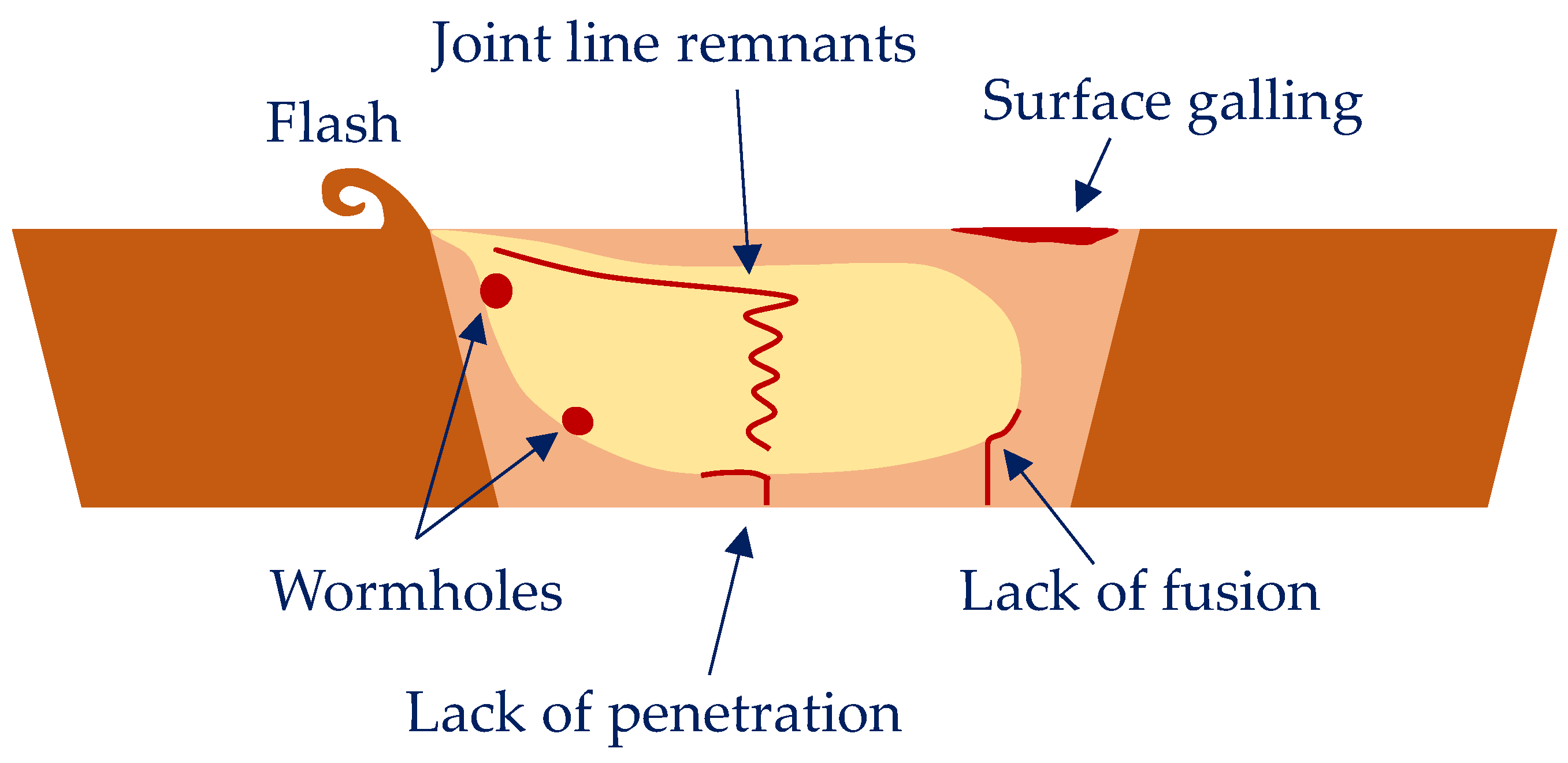
When dissimilar materials are joined, polygonal pin profiles can generate several defects such as voids, tunnel, cracks, and fragmental defects [100][23], such as evidenced in Figure 31. Palani et al. [101][24] investigate the influence of the pin profiles (i.e., square, pentagon and hexagon) on microstructure and tensile strength of dissimilar AA8011 and AA6061-T6 aluminum alloys. The authors determine that the more effective joints are found for hexagonal tool pin profile at a rotational speed of 1500 rpm, a plunge depth of 2.5 mm, and a welding speed of 40 mm/min.
In advancing side AA6061-T6 to the retreating side AA7075-T651 friction stir welded joints, Raturi et al. [102][25] investigate four different pin profiles, namely cylindrical, cylindrical tapered, cylindrical threaded with three flat faces, and truncated square pyramidal-shaped profile, hereafter referred to as trapezoidal tapered, by changing both the rotational speed (i.e., 660, 900, 1200, 1700 rpm) and the feed rate (i.e., 36, 63, 98, 132 mm/min). They observe that the cylindrical threaded with three flat faces tool pin and the cylindrical grooved tool pin with suitable intermediate tool rotation and feed rate lead to good tensile and flexural strength. The quality of friction stir welded joints, as well as the tensile strength and flexural load of the welds, are predominantly influenced by two factors: tool pin profiles and tool rotational speed. Excessively high rotational speed can lead to inferior nugget shape and inadequate joining of dissimilar metals. This is caused by the generation of excessive heat, which results in intense material softening. Consequently, poor friction, slipping, insufficient material delivery, and ultimately weak joint strength may occur. Similarly, a high feed rate can also result in reduced strength of dissimilar friction stir welded joints. An examination of the fracture surface reveals that joints prepared with appropriate tool pin profiles and process parameters exhibit ductile failure, as evidenced by the presence of micro voids and dimples in the well-bonded region. However, in contrast, some joints prepared with very high tool rotational speeds exhibit tearing, rupture, and brittle failure. On the same dissimilar joints, Raturi and Bhattacharya [103][26] study the wear phenomenon using a right-hand threaded with three intermittent flat faces tool pin at a 900 rpm tool rotation and a 98 mm/min welding speed.
The decrease in the mechanical performance from a simple pin profile (i.e., triangular) to a complex pin profile (i.e., hexagonal) occurs due to the decrease in traverse force and the enhanced structural stiffness with an increase in the number of pin sides and the resulting reduction in the bending moment and shear force [104][27]. Yuvaraj et al. [105][28] investigate simple HSS tool pin profiles (i.e., square, cylindrical, and triangle) in the welding of AA7075-T651 and AA6061 aluminum plates by finding that the best joints result in a square profile tool pin with a tool offset of 0.9 mm and a tool tilt angle of 2 degrees. In this case, the joint exhibits fine grains along the stir zone due to adequate heat generation. Furthermore, the triangular pin reveals granular grain structure due to an additional heat generation and a consequent turbulent flow of material. Krishna et al. [106][29] investigate three pin profiles (i.e., straight cylinder, straight square and tapered hexagon) on Al 6061 and Al 7075 joints. The authors find that, by using the straight cylinder tool pin profile with a rotational speed of 950 rpm, a welding speed of 60 mm/min and 6061 in the advancing side, it is possible to obtain higher mechanical properties due to the geometrical configuration of the tool pin that does not show sharp edges, also providing smooth and perfect welding (see Figure 42). The other configurations, characterized by a sharp edge, do not lead to efficient and smooth welding.
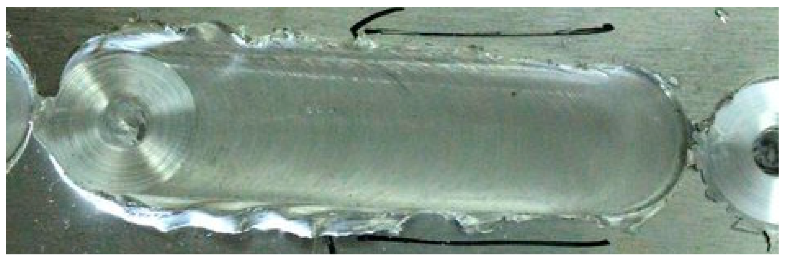
Figure 42.
Smooth and perfect welding.
El-Hafez and El-Megharbel [107][30] weld dissimilar aluminum alloys AA2024-T365 and AA5083-H111 by using square, triangular, and stepped profiles. They find that the square pin produces the best strength coupled with a welding speed of 16 mm/min and a rotational speed of 900 rpm due to the pulsed action (four pulses per revolution) that produces a good metal flow and, consequently, a good stirring, in agreement with [108,109][31][32]. Shine and Jayakumar [97][20] perform dissimilar FSW between AA5083-H111 and AA6061-T6 aluminum alloy by using three pin profiles (i.e., straight square, threaded cylinder, and tapered cylinder). From the experimental results, they observe that the straight square pin profile shows greater hardness values in the weld nugget zone and higher tensile strength in comparison to the others.
Table 32 summarizes these experimental results.
Table 32.
Effect of tool shoulder and pin geometry.
| Ref. | Sheet Material |
Sheet Position AS/RS |
Pin Profile | Tilt Angle (°) |
Rotational Speed (rpm) | Welding Speed (mm/min) |
Axial Force (kN) | Main Results |
|---|---|---|---|---|---|---|---|---|
| [110][33] | 2017-T6 6061-T6 |
- | Straight hexagonal Straight pentagonal Straight cylindrical Straight square Taper square |
0 | 1600 | 32 | - | Straight square tool pin profile produces better metallurgical and mechanical properties. The properties are inferior to those of other pin profiles, but it is preferred because the related joint is defect-free. |
| [107][30] | 2024-T365 5083-H111 |
- | Square Triangular Stepped |
- | 900 | 16 | - | Square pin produces a good metal flow and, consequently, a good stirring. |
| [99][22] | 2024-O 6061-T6 |
- | Cylindrical Stepped |
- | 900 1400 1800 |
- | - | Cylindrical profile—at 1400 rpm—promotes the material flow. |
| [91][13] | 2024-T351 7075-T651 |
- | Flute radii: 0, 2, 3, 6, ∞ mm |
- | 900 | 150 | - | Radius equal to that of the pin leads to the strongest joint. |
| [93][16] | 5052-H32 6061-T6 |
AS RS |
Taper cylinder Threaded cylinder |
- | 900 | 60 | - | Taper pin profile leads to a fine grain microstructure. |
| [97][20] | 5083-H111 AA6061-T6 |
- | Straight square Threaded cylinder Tapered cylinder |
- | - | - | - | Straight square shows better mechanical properties. |
| [88][34] | 5083-O 6061-T6 |
- | Square cylinder Straight cylinder Tapered cylinder |
1.11 | 1568 | 39.53 | - | Straight cylinder tool guarantees higher weld quality. |
| [89][35] | 5083 6351 |
- | Partial impeller Full impeller Flat grove |
- | - | - | - | Full impeller generates enhanced material flow. |
| [111][36] | 5083 7068 |
- | Straight cylindrical Taper cylindrical Triangular tool |
- | 800 1000 1200 1400 |
30 40 50 60 |
3 4 5 6 |
The triangular tool offers the maximum tensile strength and microhardness of the investigation with the combination 1200 rpm/30 mm/min/3 kN. |
| [73][14] | 5083-H111 7075-T651 |
RS AS |
Triflute Tapered with a thread |
- | 140 280 355 450 560 | |||
| Tapered hexagon | ||||||||
| - | ||||||||
| 950 | 60 | - | Straight cylinder provides a smooth and perfect welding. |
2. Tool Tilt Angle
The tilt angle refers to the angle between the FSW tool axis and the workpiece surface. It is an important process parameter that can affect the quality and properties of the welded joint [112,113][38][39].
The tilt angle can be adjusted during the FSW process to control the heat input (i.e., Figure 53) and material flow. Generally, a larger tilt angle results in a higher heat input and more material flow, which can lead to better mixing and homogenization of the welded material. This can result in a more uniform grain structure, improved mechanical properties, and increased joint strength. Moreover, a larger tilt angle can be useful for welding thicker materials or for achieving a desired weld shape. However, if the tilt angle is too large, it can cause defects such as tunneling and hooking, which can weaken the joint [114][40]. In addition, a larger tilt angle can also increase the likelihood of thermal distortion and residual stresses in the welded joint. Conversely, a smaller tilt angle can result in a lower heat input and less material flow, which can reduce the risk of defects and thermal distortion. However, if the tilt angle is too small, it can also cause defects such as hooking, as mentioned earlier. Di Bella et al. [115][41] investigate dissimilar aluminum alloys used in shipbuilding (AA6082 and AA5083) joined using a taper threaded pin profile at the following rpm/mm/min combinations: 1000/100, 1300/75 and 1600/50. The authors find that a small spindle inclination is sufficient to significantly improve the behavior of the joint by influencing the same effectiveness of the process.
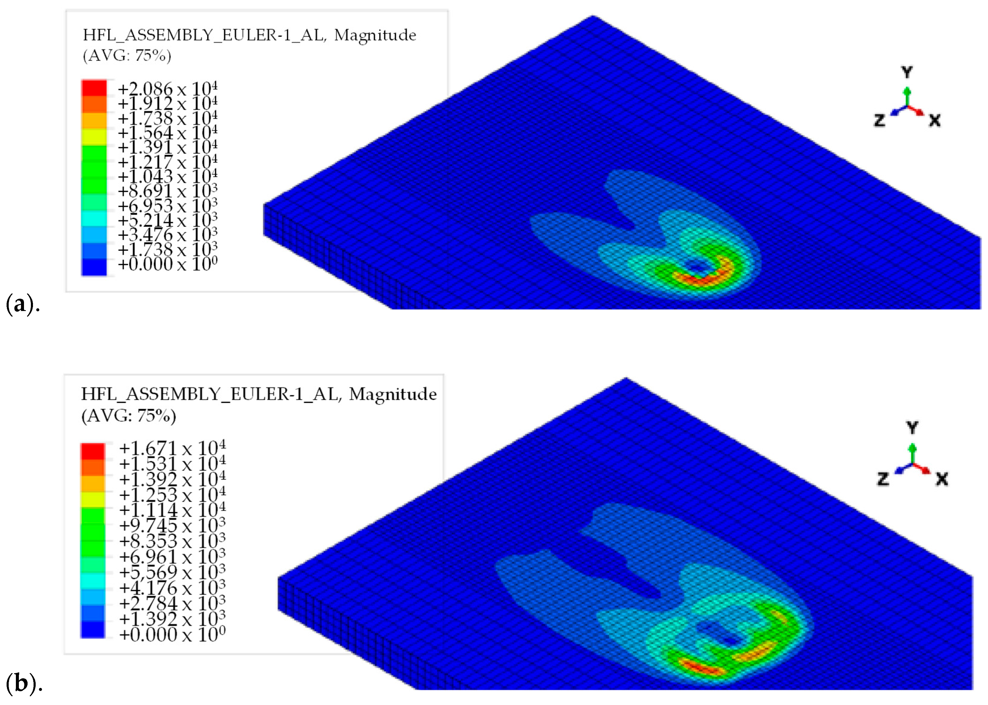
Figure 53.
Distribution of heat flux before (
a
) and after (
Yuvaraj et al. [105][28] optimize the tool tilt angle in AA7075-T651/AA6061 joints by investigating the following values: 2, 3 and 4 degrees. Applying a statistical technique, the authors observe that the tool tilt angle is the primary governing factor influencing the friction stir welded dissimilar joint tensile strength. When the tool tilt angle increases, the gap expands between the work piece and tool [116][42]. In particular, the square profile tool pin and a great tilt angle of tool (i.e., 3 degrees) improve the mechanical properties of the joint of the weld joint.
It is worth noticing that FSW tool shoulders can also contain features to increase the amount of material deformation produced by the shoulder, resulting in increased workpiece mixing and higher-quality friction stir welds. These features can consist of scrolls, ridges or knurling, grooves, and concentric circles and can be machined onto any tool shoulder profile. Scrolls are the most observed shoulder feature. The channels direct deformed material from the edge of the shoulder to the pin, thus eliminating the need to tilt the tool [117][43]. Such tools are particularly preferred for curved joints [117,118][43][44].
3. Tool Rotational Speed
The tool rotational speed represents the speed at which the welding tool rotates as it moves along the joint between the two pieces of metal being welded. During the FSW process, the rotating tool generates heat and friction, which softens the metal and creates a plasticized region around the tool. The tool then moves along the joint, pushing the softened metal behind it to create a solid-state weld.
It is a critical parameter in FSW, and it has several effects on the welding process [119,120][45][46] by influencing the following:
-
Heat generation: as the tool rotates, it generates frictional heat due to the contact between the tool and the workpiece, controlling heat generation or heat input as they relate to the material plastic flow [31][47]. Higher rotational speeds result in more heat generation, which can cause the material to soften and lead to better mixing and bonding between the two workpieces.
-
Plasticized zone size around the tool: it affects the intensity of plastic deformation and through this influences material mixing [31,73][14][47]. Moreover, a higher rotational speed can lead to a larger plasticized zone, which can result in a better bond between the two workpieces [121,122,123][48][49][50].
| 900 | ||||||||
| 140 | ||||||||
| 26.4 | ||||||||
| Triflute pin—at 280 rpm—guarantees the higher tensile properties and a defect-free joint with a wider stir zone. | ||||||||
| [ | ||||||||
| 90][37] | 5083 7075 |
- | Threaded straight cylindrical, Tapered cylindrical, Threaded tapered cylindrical |
- | 600 700 800 |
40 | - | The highest tensile strength and the defect-free joint is obtained by using the threaded tapered cylindrical pin tool at a rotational speed of 800 rpm. |
| [92][15] | 5086-O 6061-T6 |
RS AS |
Straight cylindrical Threaded cylindrical Tapered cylindrical |
1 | 1100 | 22 | 12 | Threaded pin profile guarantees defect-free joints, finer and uniformly distributed precipitates formation, circular onion rings and smaller grain. |
| [102][25] | 6061-T6 7075-T651 | AS RS |
Cylindrical Cylindrical tapered Cylindrical threaded Trapezoidal tapered |
660 900 1200 1700 |
36 63 98 132 |
Cylindrical threaded with three flat faces tool pin and cylindrical grooved tool pin—at intermediate tool rotation and feed rate—lead to good tensile and flexural strength. | ||
| [105][28] | AA6061 7075-T651 |
- | Square Cylindrical Triangle |
2 3 4 |
- | - | - | Square pin—with a 2° tilt angle—exhibits fine grains along the stir zone due to adequate heat generation. Triangular pin reveals granular grain structure. |
| [106][29] | 6061 7075 |
RS/AS AS/RS |
Straight cylinder Straight square |
- Weld quality: an exceedingly low rotational speed can result in incomplete weld formation and poor bonding between the two workpieces. On the other hand, if the rotational speed is too high, it can lead to defects in the weld, such as poor surface (flash), voids, porosity, and tunneling or formation of wormholes because of the excessive heat input.
-
Tool wear: higher rotational speeds can lead to more wear on the tool, which can reduce its lifespan.
-
Welding force (i.e., required to push the tool through the workpiece): the rotational speed of the tool can also affect the force. Higher rotational speeds generally require higher forces to maintain the tool’s position and prevent it from slipping out of the joint.
Moreover, this parameter affects the joint behavior as a function of the sheet aluminum alloy in different ways [124][51]. Changing the tool rotation rate influences the size and macrostructure of weld nugget zone in a friction stir welded AA2524-T351 aluminum alloy. The width of this zone increases with increase in the tool rotation rate. As the tool rotates at a high speed, the area of the recrystallized zone expands with increasing temperature, leading to this phenomenon [125][52]. Generally, insufficient energy is provided for dynamic recrystallization at lower rotational speeds, resulting in incomplete dynamic recrystallization and ineffective grain refinement strengthening. At higher rotational speed, the higher strength in weld nugget zone is attributed to smaller grain size [126][53]. In the weld of the AA5086-H32 alloy, lower rotational speed produces various defects due to the production of inadequate heat resulting in improper softening of the material [127][54]. The excessive heating and deformation caused by tool rotation in AA5052-O lead to an increase in b-phase (Mg2Al3) particles through magnesium atom diffusion towards grain boundaries. The dissolution of these intermetallic particles within the weld nugget zone subsequently results in reduced joint strength [128][55]. As the rotational speed of the FSW tool increases for the 6082-T6 aluminum alloy, the weld temperature first rises and then falls, leading to the formation of smaller equiaxed recrystallized grains in the nugget zone. Moreover, the hardness of the nugget zone increases as the rotational speed is raised to 1200 rpm due to the enhanced dislocation density. This increase in dislocations is attributed to the precipitation and dissolution of the second phase as well as the refinement of the aluminum matrix grain size in the microstructure of the zone [129][56]. For friction stir-welded 7075-T6 Al alloys, there exists a strong relation between rotational speed and weld properties, i.e., rise of the rotating speed from 600 to 1550 rpm increases the average nugget grain size from 6.8 to 8.9 mm. Also, at a medium rotating speed, the optimum mechanical properties are achieved [130][57].
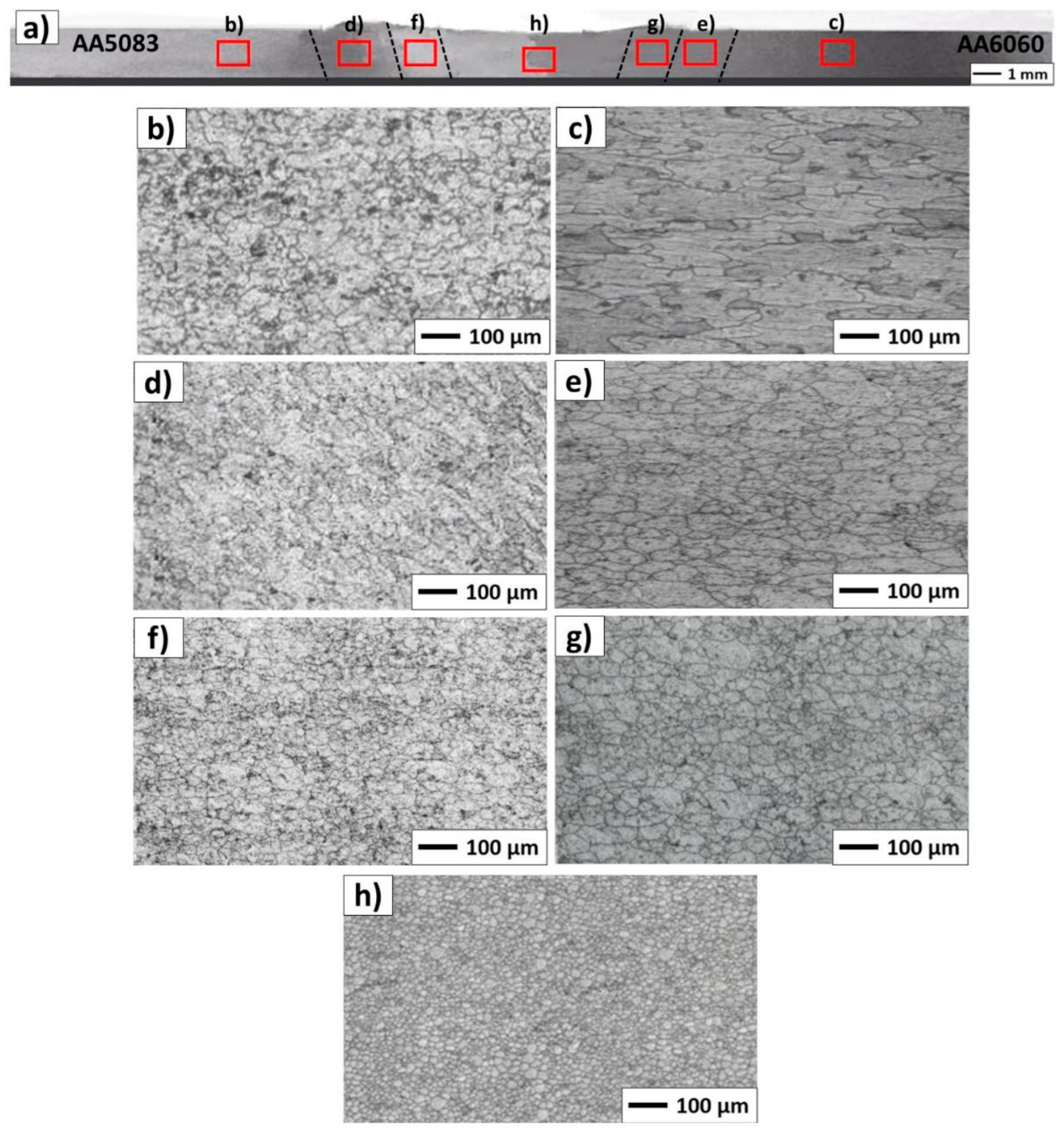
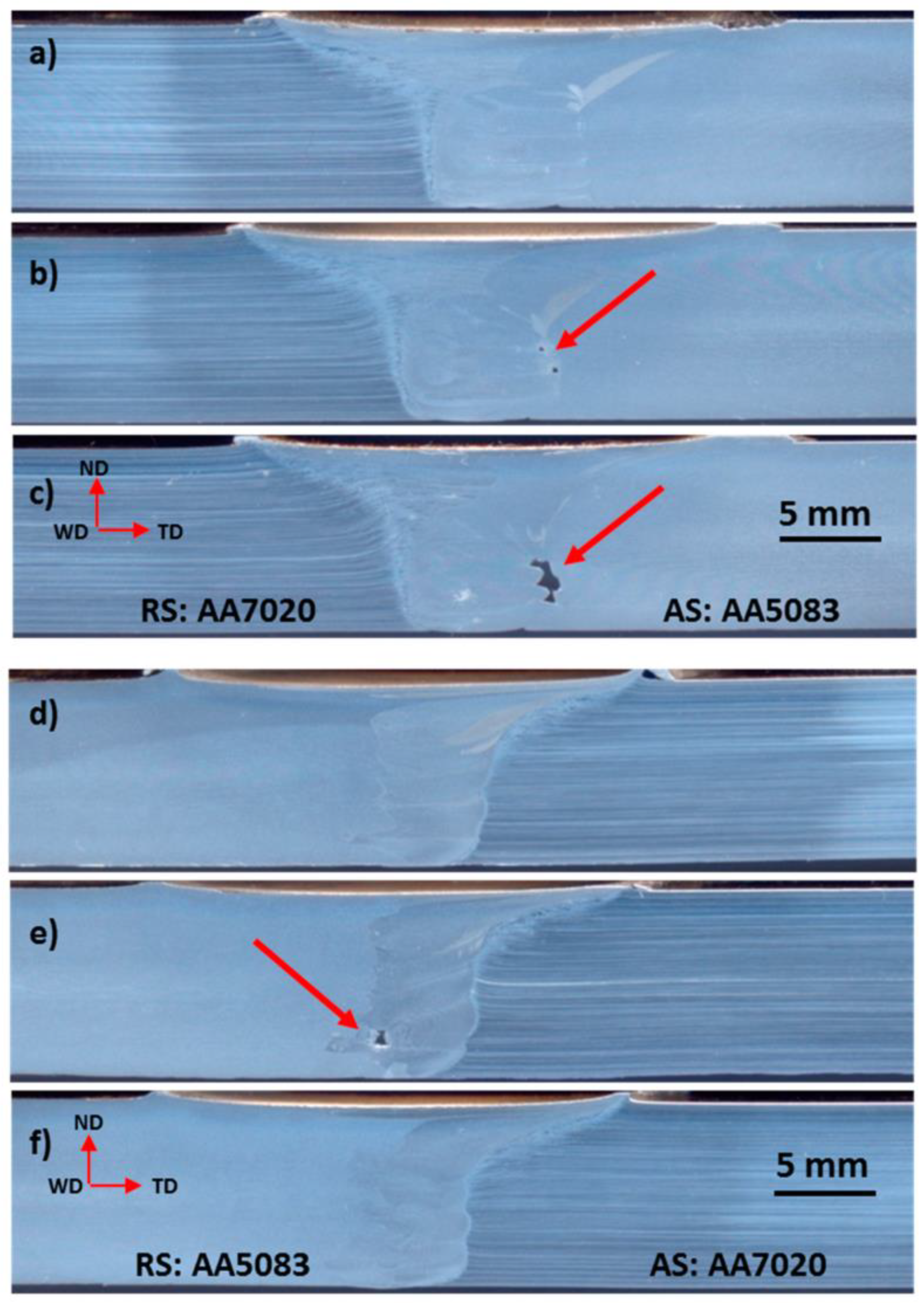
Several studies on FSW involve dissimilar aluminum alloys [31,131][47][58]. Ghaffarpour et al. [132][59] join dissimilar aluminum alloys of 5083-H12 in the retreating side and 6061-T6 in the advancing side, changing the rotational speed (i.e., 700, 1600, 2500 rpm) in combination, respectively, with the pin diameter (i.e., 2, 3, 4 mm), the shoulder diameter (i.e., 10, 12, 14 mm), and the traverse speed (i.e., 25, 212.5, 400 mm/min). The authors find that the effect of the pin diameter is not as pronounced as the effect of the rotational speed. As the rotational speed and pin diameter increase, the input heat increases, resulting in higher tensile strength. Moreover, the effect of the rotational speed is more significant compared to the effect of the traverse speed and the shoulder diameter. Thermocouple measurements, tool torque, extent of material mixing, and macrostructural observations all indicate that the temperature under the tool is more strongly dependent on the rotation than the traverse speed as observed also in AA5083-AA6082 joints [133][60]. The increase in tensile strength with greater friction heat can be attributed to the improved mixing of dissimilar alloys due to proper stirring resulting from the higher heat input. Additionally, the plasticization effect during FSW is enhanced at higher heat inputs. Consequently, softer materials are easier to mix and stir. Nevertheless, the strength exhibits a maximum value with an increase in heat input, implying that further increments in heat generation lead to a reduction in strength beyond a certain optimum heat level. The lowest hardness is recorded in the heat affected zone of the AA6061-T6 sheet. It is also observed that when the tool rotational speed increases, the hardness of the mixing zone reduces. This can be explained in the following ways. Firstly, the higher rotational speed generates more heat, leading to local annealing in both sheets. Secondly, the frictional heat increases the temperature above the aging temperature of the 6061-T6 sheet. Consequently, the fine Mg2Si precipitates, which serves as the hardening phase in AA6061, either dissolving or growing, leading to a decrease in hardness. This same phenomenon can occur in 5083-H12 as well. Furthermore, excessive heat can cause grain growth in both alloys, thereby contributing to a decrease strength and hardness. Consequently, the optimal rotational speed takes intermediate values [134][61]. Palanivel et al. [135][62] produce AA5083-H111 (in the retreating side)/AA6351-T6 (in the advancing side) joints using three different tool rotational speeds (i.e., 600 rpm, 950 rpm and 1300 rpm) and five different tool pin profiles (i.e., straight square, straight hexagon, straight octagon, tapered square, and tapered octagon) with a constant welding speed of 60 mm/min, an axial force of 8 kN and a tilt angle of 0 degrees. The high-carbon high-chromium steel tool is characterized by a shoulder diameter of 18 mm, a pin diameter of 6 mm and a pin length of 5.7 mm. The two parameters affect the strength due to variations in material flow behavior, loss of cold work in the AA5083 heat-affected zone, dissolution and AA6351 over-aging of precipitates and formation of macroscopic defects in the weld zone. The best friction stir welded joint is obtained for a tool rotational speed of 950 rpm and a straight square pin profile. Mastanaiah et al. [121][48] study the effect of process parameters on dissimilar friction stir welds in AA2219-T6/AA5083 aluminum alloys, placing 5083 in the advancing side. In particular, the authors investigate five levels of rotational speed (i.e., 400, 800, 1200, 1600, 2000 rpm), welding speed (30, 210, 390, 570, 750 mm/min), and tool offset (−2, −1, 0, +1, +2 mm) using an H13-grade tool steel tool with a 15 mm diameter shoulder, a frustum-shaped threaded pin of a 6 mm top diameter and a 4 mm bottom diameter and a tilt angle of 2 degrees. Welds free of defects can be achieved under a wide range of conditions. However, it is important to note that when performing welds at the lowest rotation speed, highest traverse speed, and with a tool offset towards the AA2219 alloy side, defective welds may occur. The degree of intermixing is determined by the tool rotation speed and traverse speed. It is possible to observe that at higher tool rotation speeds and lower tool traverse speeds, there is a greater degree of intimate mixing between dissimilar alloys. Laska et al. [131][58] produce dissimilar butt joints from two alloys, AA5083 in the advancing side and AA6060 in the retreating side, by changing the rotational speed from 800 to 1200 rpm with a constant welding speed of 100 m/min and a tilt angle of 2 degrees. The tool shoulder has a flat surface with a diameter of 18 mm. The pin length measures 2.5 mm. The pin itself has a hexagonal shape with a distance across the flats of 6 mm. The pin is made of a 73MoV52 steel, while the shoulder is composed of a X210Cr12 steel. The findings demonstrate that an increase in tool speed leads to an increase in hardness within the weld nugget zone. This is attributed to the higher heat input and more efficient recrystallization process. The weld with the highest tool rotational speed (see Figure 64) exhibits the highest hardness in the nugget zone. Goriparthi et al. [136][63], in a comparative study between TIG welding and FSW, investigate dissimilar AA5083-O and AA7075-T651 aluminum alloys at different rotational speeds (i.e., 800, 1000, 1100, 1200, and 1400 rpm) and a welding speed of 40 mm/min, with a tool characterized by a straight square pin profile. They observe that at lower rotational speed, the generated heat is not sufficient, and at higher tool rotational speeds, excessive heat causes the overflow of solidified materials and defect formation. Devaraju et al. [137][64] study dissimilar 2024/6061 aluminum alloys using a tool with a shoulder diameter of 24 mm, a pin diameter of 8 mm, a pin length of 5.8 mm and a tilt angle of 1.5 degrees. The authors investigate three different rotational speeds (i.e., 900, 1120, and 1400 rpm) at a welding speed of 40 mm/min and an axial force of 5 kN. The presence of a well-defined grain boundary region distinguishes the recrystallized area known as the stirring zone from the distorted regions within the thermo-mechanically affected zone. Improved tensile properties are evident at a rotational speed of 900 rpm.
Conversely, the rise of the heat input decreases the hardness of the heat-affected zone, where recrystallization does not occur. In the heat-affected zone on the AA6060 side, the lowest density of dislocations with the highest mobility is observed, contributing to a reduction in strength within this zone. Das and Toppo [138][65] investigate three different tool rotational speeds (i.e., 900, 1100 and 1300 rpm) for producing AA6101-T6 (in advancing side)/AA6351-T6 (in retreating side) joints using a high-carbon and high-chromium steel taper cylindrical thread pin with a tilt angle of 2 degrees and a welding speed of 16 mm/min. The tool has a shoulder diameter of 25 mm, a big pin diameter of 8 mm, a small pin diameter of 6 mm and a pin length of 11.7 mm. In Charpy impact tests, it is observed that the minimum energy occurs at 900 rpm. This phenomenon can be attributed to the low friction pressure and insufficient friction time, which result in inadequate generation of frictional heat and insufficient time for the formation of a strong bond between the two dissimilar metals. However, as the rotational speed rises to 1100 rpm, the impact energy of the joint also increases. Subsequently, as the rotational speed further escalates to 1300 rpm, the impact energy decreases. This decline in impact energy could be attributed to grain refinement taking place in the weld zone due to the high heat generated.
Das et al. [139][66] analyze other mechanical properties of these two alloys, changing the rotational speed from 900 rpm to 1500 rpm and altering the axial force (i.e., 4, 5, 6, 8 kN) with a constant welding speed of 60 mm/min and using an EN32 steel tool with a cylindrical threaded pin profile displaying a tool tilt angle of 2 degrees. The flat-faced shoulder diameter, pin diameter and tool pin length are 18 mm, 6 mm, and 5.85 mm, respectively. The authors find that the rotational speed of 1300 rpm produces better mechanical and metallurgical properties joints. At lower rotational speeds, the tensile strength tends to be poor primarily because the tool stirring action is inadequate. This insufficient stirring leads to the generation of minimal frictional heat at rotational speeds of 900 rpm and 1100 rpm. Consequently, the material flow is compromised, resulting in lower tensile strength. However, an increase in rotational speed (1300 rpm) leads to an improvement in ultimate tensile strength. This occurs because the heat input at this speed is sufficient, promoting better weld quality. The weld region exhibits equiaxed fine grains, further enhancing tensile strength. Nevertheless, when the rotational speed exceeds a certain threshold (1500 rpm), excessive heat input becomes a factor. This excess heat input causes reprecipitation and reduces the dislocation density of strengthening precipitates such as Mg2Si. As a result, tensile strength is lowered. In bending tests, when the rotational speed is set to 900 rpm, the joints demonstrate lower ductility. Additionally, micro cracks can be observed on the outer surface of the weld joint. These issues arise due to improper mixing of the metals and insufficient downward force applied during the process. At 1100 rpm, there is an increase in heat generation, resulting in an improved flow of the softened mixed material comprising the two alloys. Consequently, the ductility of the joints improves. At a high rotational speed of 1500 rpm, the material flow becomes excessive due to the intense heat generated between the tool shoulder and the workpiece interface. This excessive flow causes the intermetallic compound Mg2Si to break, leading to a decrease in bending strength. However, when the rotational speed is set to 1300 rpm, the joint exhibits good ductility. This is attributed to the uniform interdiffusion of the intermetallic compound Mg2Si in the weld nugget region. As a result, the friction stir welded (FSW) joints demonstrate enhanced bending strength. Micro hardness tests reveal variations in hardness at the nugget region. These variations occur due to differences in heat input during the FSW process, which also impact the microstructures of the base alloy. At 900 rpm, the hardness is generally lower compared to that of the base alloys and other joints. This can be attributed to a softening effect that occurs at the weld joints. The hardness is dependent on the distribution of the intermetallic compound Mg2Si and the grain microstructure within the nugget region. At a rotational speed of 1300 rpm, the rate of heat input increases. This leads to the formation of fine equiaxed grains and a well-spaced microstructure within the weld nugget region. As a result, the weld nugget region exhibits an optimum micro hardness value. This indicates that the hardness at the nugget region is influenced by the grain size. However, as the rotational speed further increases to 1500 rpm, there is a decrease in hardness. This occurs primarily due to the high heat input, which leads to softening in the nugget region. Consequently, there is a reduction in grain size and the dissolution of strengthening precipitates, such as Mg2Si, further contributing to the drop in hardness. Aval [140][67] conducts a study on the impact of rotational speed on residual stress in dissimilar welded aluminum plates of two alloys, 6082-T6 in the advancing side and 7075-T6 in the retreating side, using an H13 steel tool with a shoulder of 23 mm in diameter, a triangular frustum pin, and a tilt angle of 2 degrees. During the experiments, various tool rotational speeds are tested, including 800, 1000, 1200, and 1400 rpm. Additionally, welding speeds of 90, 120, and 150 mm/min are used. However, only the welds created using rotational speeds of 1000 and 1200 rpm with welding speeds of 90 and 120 mm/min yield satisfactory results. The findings of the author reveal that as the rotational speed increases (from 1000 to 1200 rpm) and the traverse speed decreases (from 120 to 90 mm/min), both factors contribute to the processes of increased heat generation, higher peak temperatures, and reduced maximum tensile residual stress. Interestingly, these results contradict the findings of Giorgi et al. [141][68]. To explain these contradictory results, Richards et al. [142][69] propose that the stress profile observed in friction stir welding (FSW) is a result of the mismatch in plastic strains induced by steep temperature gradients during the welding process. As heat is generated by the FSW operation and distributed within the component while the tool advances, these plastic strains occur. Therefore, it can be inferred that peak temperatures alone do not solely determine the maximum tensile residual stress. Instead, the temperature gradient, particularly the material cooling rate and its uniformity, exert a more significant influence on the maximum tensile residual stress. These conclusions are supported by the findings of Campanelli et al. [143][70], who conducted an analysis on the effects of preheating the weld zone using a high-powered laser. Haribalaji et al. [144][71] investigate the FSW of two aluminum alloys, AA2014 in the advancing side and AA7075 in the retreating side. The process parameters are 1000, 1200, and 1400 rpm of rotational speed, 30, 45, and 60 mm/min of welding speed, 3, 6, and 9 kN of axial force, three different tool pin profiles (i.e., straight cylinder, tapered, and threaded pin) and a tilt angle of 0, 1, and 2 degrees. The tool, constructed from high-carbon steel H13, has a shoulder diameter of 20 mm and a pin diameter of 6 mm. The authors observe that rotational speed and axial force are significant factors in tensile strength and microhardness. Setting them correctly can prevent the formation of defect-free welds. The best welding parameters for achieving maximum tensile strength are a rotation speed of 1000 rpm, a welding speed of 45 mm/min, an axial force of 6 kN, and a tilt angle of 2 degrees. On the other hand, for achieving maximum hardness, the optimal parameters are a rotation speed of 1000 rpm, a welding speed of 60 mm/min, an axial force of 6 kN, and a tilt angle of 2 degrees. These optimal parameters are obtained by utilizing a threaded tool pin profile. Zuiko et al. [145][72] investigate two combinations of rotational and welding speed (500 rpm/380 mm/min and 1000 rpm/760 mm/min) on the AA5182/AA2519 joint placing the two sheets on the retreating side and advancing side, respectively. The welding tool consists of a shoulder of 12.5 mm in diameter and a cylindrical pin of 2.7 mm in length. For both combinations, defect-free welds are obtained. The first combination allows to obtain a slightly higher ultimate tensile strength in tensile tests. Tarkono et al. [146][73] investigate the quality of dissimilar aluminum alloys AA1100 and AA5052 by varying the rotational speed (i.e., 1750, 2230, and 3500 rpm, with a welding rate of 22 mm/min). They find that a speed of 1750 rpm induces defect of the hole, rough surface, and no stable welding, a speed of 2230 rpm induces rough surface but more stable welding, and a speed of 3500 rpm induces smooth surface and stable welding. Sivaselvan et al. [147][74] study friction stir welding joints between AA6061 and AA5083 by varying both the rotational (i.e., 1100, 1300, and 1500 rpm) and welding speed (30, 45, and 60 mm/min). The authors find that the increase in rotational speed leads to poor wear performance, whereas the increase in welding speed shows better wear performance. Heramo and Workneh [148][75] investigate AA6061-T6/AA5052-H32 dissimilar joints by varying rotational speed (i.e., 900, 1100, and 1400 rpm), transverse speed (i.e., 40, 50, and 60 mm/min), and pin profiles (cylindrical, conical, and square). In particular, the square pin profile, the rotational speed of 1400 rpm, and the transverse speed of 40 mm/min are the optimal parameters. Wang et al. [149][76] join 2219-T8 and 2195-T8 aluminum alloys using an H13 steel tool with a concave shoulder of 21 mm in diameter and a threaded cylindrical pin of 8 mm in diameter and 5.8 mm in length. The process occurs by varying rotational speed (from 800 rpm to 1200 rpm), welding speed (from 200 mm/min and 800 mm/min) and position of sheets. The results show that sound FSW joints are obtained under all the welding conditions.
As the sheet thickness increases, the tool rotational speed typically needs to be adjusted to accommodate the additional material volume and ensure adequate heat generation. Thicker sheets require greater heat input, so increasing the rotational speed helps in generating more frictional heat at the interface between the tool and the workpiece. However, the rotational speed cannot be increased infinitely, as excessive speeds can lead to overheating or material defects. Therefore, a balance must be struck to achieve the desired heat input without compromising weld quality.
Table 43 summarizes these experimental results.
Table 43.
Effect of tool rotational speed.
| Ref. | Sheet Material |
Sheet Position AS/RS |
Pin Profile | Tilt Angle (°) |
Rotational Speed (rpm) | Welding Speed (mm/min) |
Axial Force (kN) | Main Results |
|---|---|---|---|---|---|---|---|---|
| [146][73] | 1100 5052 |
- | - | - | 1750 2230 3500 |
22 | - | A speed of 3500 rpm induces smooth surface and stable welding. |
| [144][71] | 2014 7075 |
AS RS |
Straight cylinder Tapered Threaded |
0 1 2 |
1000 1200 1400 |
30 45 60 |
3 6 9 |
Rotational speed and axial force are significant factors in tensile strength and microhardness. The best combination for tensile properties is 1000 rpm/45 mm/min/6 kN/2°. The best combination for hardness properties is 1000 rpm/60 mm/min/6 kN/2°. These optimal parameters are obtained by utilizing a threaded tool pin profile. |
| [149][76] | 2195-T8 2219-T8 |
AS/RS RS/AS |
Threaded cylindrical | - | 800 1200 |
200 400 800 |
- | The sound FSW joints are obtained under all the welding conditions. |
| [121][48] | 2219 5083 |
RS AS |
Frustum threaded | - | 400 800 1200 1600 2000 |
30 210 390 570 750 |
- | Higher tool rotation speeds and lower tool traverse speeds promote intimate mixing between dissimilar alloys. |
| [137][64] | 2024 6061 |
. | - | 1.5 | 900 1120 1400 |
40 | 5 | The presence of a well-defined grain boundary region distinguishes the recrystallized area (stirring zone) from the distorted regions within the thermo-mechanically affected zone. |
| [145][72] | 2519 5182 |
AS RS |
Cylindrical | - | 500/380 1000/760 |
- | For both the combinations, the joint is defect-free. The 500/380 ratio allows a slightly higher ultimate tensile strength in the tensile test. | |
| [148][75] | 5052-H32 6061-T6 |
- | Cylindrical Conical Square |
- | 900 1100 1400 |
40 50 60 |
- | The square pin profile, the rotational speed of 1400 rpm, and the transverse speed of 40 mm/min are the optimal parameters. |
| [131][58] | 5083 6060 |
AS RS |
Hexagonal | 2 | 800 1000 1200 |
100 | - | An increase in tool speed leads to an increase in hardness within the weld nugget zone due to both the higher heat input and a more efficient recrystallization process. |
| [147][74] | 5083 6061 |
AS RS |
Cylindrical threaded | 2 | 1100 1300 1500 |
30 45 60 |
- | The increase in rotational speed leads to poor wear performance, whereas the increase in welding speed shows better wear performance. |
| [132][59] | 5083-H12 6061-T6 |
RS AS |
Diameter: 2, 3, 4 mm |
- | 700 1600 2500 |
25 212.5 400 |
- | As the rotational speed and pin diameter increase, the input heat increases, resulting in higher tensile strength. |
| [133][60] | 5083 6082 |
AS/RS RS/AS |
- | - | 280 560 840 |
100 200 300 |
- | Higher rotational speed generates more heat, causing grain growth in both alloys and Mg2Si precipitation. |
| [135][62] | 5083-H111 AA6351-T6 |
RS AS |
Straight square Straight hexagon Straight octagon Tapered square Tapered octagon |
0 | 600 950 1300 |
60 | - | Rotational and welding speeds affect the strength due to variations in material flow behavior, loss of cold work in the AA5083 heat-affected zone, dissolution and AA6351 over-aging of precipitates and formation of macroscopic defects in the weld zone. |
| [136][63] | 5083-O 7075-T651 |
- | Straight square | - | 800 1000 1100 1200 1400 |
40 | - | The defect-free joint is obtained for a rotational speed of 1100 rpm. At a lower speed, heat is not sufficient. At higher speeds, heat is excessive. |
| [140][67] | 6082-T6 7075-T6 |
AS RS |
Triangular frustum | 2 | 800 1000 1200 1400 |
90 120 150 |
- | As the rotational speed increases (from 1000 to 1200 rpm) and the traverse speed decreases (from 120 to 90 mm/min), both factors contribute to increased heat generation, higher peak temperatures, and reduced maximum tensile residual stress. |
| [138][65] | 6101-T6 6351-T6 |
AS RS |
Taper cylindrical thread | 2 | 900 1100 1300 |
16 | - | With increasing rotational speed, the impact energy first increases and then decreases. For low rpm, the heat is insufficient. For high rpm, the heat is high, inducing a grain refinement. |
| [139][66] | 6101-T6 6351-T6 |
AS RS |
Cylindrical threaded | 2 | 900 1100 1300 1500 |
60 | 4 5 6 8 |
At lower rotational speeds, the tensile strength tends to be poor primarily because the tool stirring action is inadequate. An intermediate value of 1300 rpm generates a sufficient heat input, promoting better weld quality. At a high rotational speed, the heat is excessive. |
4. Welding Speed
The welding speed in friction stir welding refers to the rate at which the tool moves along the joint line during the welding process. It is also known as the traverse speed, feed rate or travel speed. It can vary depending on several factors, including the material being welded, the thickness of the workpieces, and the desired quality and strength of the joint. Generally, it is relatively slower compared to traditional fusion welding processes such as arc welding or laser welding.
The typical welding speeds in friction stir welding can range from a few centimeters per minute (cm/min) to several tens of centimeters per minute depending on specific application. However, it is important to note that the focus in FSW is not on achieving high welding speeds but rather on controlling the process parameters to ensure proper heat generation, mixing, and consolidation of the material.
The selection of the optimal welding speed in FSW involves a trade-off between process efficiency and joint quality. A slower welding speed allows for better heat input control, enhanced material mixing, and improved joint integrity, which is particularly important for high-strength materials or critical applications. It can be also associated with defects such as tunneling (i.e., Figure 75). On the other hand, increasing the welding speed can improve productivity but may require careful adjustments to maintain the desired joint properties.
The welding speed plays a crucial role in determining the exposure time of frictional heat per unit length of the weld. This, in turn, affects the grain growth and precipitates within the welded material. Achieving an optimal exposure time and the appropriate translation of stirred material leads to effective consolidation of the material, resulting in finer grains. For instance, when a joint is subjected to such conditions at a welding speed of 63 mm/min, it exhibits the highest resistance. This suggests that the combination of the specific welding speed and a corresponding exposure time promotes favorable consolidation and grain refinement, ultimately enhancing the overall strength and quality of the joint. The factors that determine the tensile strength of dissimilar aluminum alloy joints are the presence of macroscopic defects in the weld zone and the degree of plastic flow and the amount of mixing of both materials.
Welding speed is always investigated in combination with tool rotational speed to obtain a defect-free joint with a good metallurgical bond and mechanical properties. Devaiah et al. [153][78] use FSW for joining two aluminum alloys, AA5083-H321 in the advancing side and AA6061-T6 in the retreating side, using an H13 steel tool with a cylindrical taper threaded pin profile, changing the welding speed (i.e., 40, 63, 80 and 100 mm/min) and keeping a constant rotational speed (i.e., 1120 rpm) and tilt angle (i.e., 2.5 degrees). The tool has a shoulder diameter of 18 mm, a pin diameter of 6 mm and a pin length of 4.7 mm. The optimal joint is made with a tool rotation speed of 1120 rpm and a welding speed of 80 mm/min. This combination induces an adequate heat generation and proper mixing of the material in the weld zone. Furthermore, it is possible to observe that the weld zone exhibits the formation of finer grains, primarily attributed to the occurrence of dynamic recrystallization. This phenomenon contributes to the refinement of the grain structure within the weld zone. When examining the fracture surface of both tensile and impact specimens in AA5083 to AA6061 weldments, a ductile fibrous fracture is evident at the weld zone. This fracture morphology indicates that the joint possesses good ductility and toughness characteristics. The welding speed significantly influences the formation of the plastic flow region during friction stir welding. Specifically the choice of welding speed determines the extent and quality of the mixing that occurs within the material. It has been observed that at the lowest or highest welding speeds, the mixed flow region is absent or poorly formed in the joints. Jia et al. [154][79] optimize the welding parameters of the friction stir welding of dissimilar 6061-T6 (in the advancing side)/5083-H111 (in the retreating side) aluminum alloys. In particular, welding parameters include rotational speeds of 2000, 2400, and 2800 rpm, traverse speeds of 1200, 1500, and 1800 mm/min, and plunge depths of 0.20, 0.25, and 0.30 mm. Experiments are conducted using a welding tool equipped with a right-hand threaded pin surface and three involute grooves on the shoulder. The tool is welded at a tilt angle of 2.5 degrees and has a pin length of 2.65 mm. The pin bottom diameter measures 3 mm, while the shoulder diameter is 14.0 mm. The yield strength of the welded joint first increases and then decreases with increasing the traverse speed. A higher traverse speed reduces the amount of frictional heat generated and makes it difficult to achieve sufficient material flow and mixing. In FSW, the tool rotation and traverse speed create frictional heat, which softens the material and allows for plasticized material flow and mixing. However, when the traverse speed is set too high, there is insufficient time for the heat to build up, resulting in inadequate softening of the material. Insufficient frictional heat leads to challenges in achieving proper material flow and mixing. The softened material is not able to flow and mix effectively, which can negatively impact the weld quality. Inadequate mixing can result in defects such as incomplete bonding, lack of homogeneity, or improper consolidation of the weld. The traverse speed has a significant impact on the material mixing of dissimilar aluminum alloys. A lower traverse speed is more conducive to the mixing of dissimilar aluminum alloys. Anandan et al. [155][80] investigate a friction stir welded joint between dissimilar 7050-T7651 and 2014A-T6 aluminium alloys changing the welding speed from 25 to 85 mm/min (i.e., 25, 45, 65, 85 mm/min) using a cylindrical tapered tool pin made of H13 tool steel with a tilt angle of 2 degrees and a rotational speed of 1000 rpm. The authors observe better mechanical and metallurgical properties than those of other welding speeds at 65 mm/min because of proper material mixing and finer grains obtained in the weldment. At low welding speeds, it is possible to observe the formation of keyholes and high concavity, while at high welding speeds the stir zone decreases by about 37%. Keyholes and concavity are mainly formed as a result of increased heat generated during the FSW process. Conversely, the decrease in heat generation leads to a reduction in the size of the stir zone. Dimov et al. [156][81] focus on the mechanical behavior of a AA6061-T651/AA7075-T651 dissimilar friction stir weld by controlling pin length, rotational speed, advancing speed and vertical force to reach 5.75 mm, 400 rpm, 120 mm/min, and 10 kN, respectively. The meso-scale strain distribution is primarily influenced by the local alloy composition, which is identified as the critical parameter. Additionally, at a smaller scale, the presence of intermetallic Mg-Si- and Fe-rich particles further contributes to strain localization within each individual alloy. Khan et al. [157][82] select aluminum alloys AA2219-O in the advancing side and AA7475-T761 in the retreating side as base materials for welding using a high-carbon high-chromium steel cylindrical tool displaying a threaded pin with a 14 mm shoulder diameter and a 4 mm pin diameter, with a tilt angle of 2.5 degrees, two rotational speeds (i.e., 710 and 1120 rpm) and two welding speeds (i.e., 160 and 250 mm/min). The authors discover that an increased strain rate results in a greater flow stress necessary for plastic deformation. Nonetheless, when considering the relationship between strain rate and the speed at which the tool traverses, it becomes evident that the dependence is more pronounced compared to the rotational speed of the tool. A higher traverse speed leads to a reduction in heat input per unit weld length and an increase in strain rate. Both factors contribute to an increase in flow stress. Additionally, as the traversing speed increases, the net traverse force exerted on the tool experiences a significant rise. Ahmed et al. [158][83] join aluminum alloys AA7075-T6 in the retreating side and AA5083-H111 in the advancing side using an H13 steel with an 18 mm diameter concave shoulder and a 4.8 mm long unthreaded taper cylindrical pin with a tilt angle of 3 degrees at a constant rotation rate of 300 rpm and different traverse speeds of 50, 100, 150, and 200 mm/min. Despite using the same parameters for the two alloys, the authors report a display of different responses in terms of the recrystallized fine grains after FSW. In the case of AA7075, significant grain refinement occurs in the nugget zone with an average grain size of 6 μm at a welding speed of 50 mm/min, which is further reduced to 2 μm by increasing the welding speed to 200 mm/min. On the other hand, AA5083 joints in the nugget zone exhibit a relatively coarser recrystallized grain structure with an average grain size of 9 μm at 50 mm/min, which decreases to 3 μm at 200 mm/min. These findings indicate that the initial characteristics of the materials have a substantial impact on the final grain structure after FSW. The crystallographic texture in the nugget zone displays a simple shear texture, with no considerable influence observed when varying the welding speed. Alemdar et al. [159][84] investigate the dissimilar AA2198-T8/AA2024-T3 joint varying the welding speed (i.e., 36, 76, 102, 146, and 216 mm/min) at a rotational speed of 960 rpm using a tapered threaded pin with a concaved shoulder with a tilt angle of 2 degrees. As the welding speed increases from 36 mm/min to 216 mm/min, the area of the heat-affected zone initially increases and then decreases due to different welding temperatures. The joints formed at 76 mm/min exhibit excellent tensile characteristics.
Thicker sheets generally require slower welding speeds to allow sufficient heat transfer and plasticization of the material. Slowing down the welding speed ensures that the heat generated by the friction stir process has enough time to propagate through the thickness of the sheets and achieve the desired weld quality. A slower welding speed also helps in maintaining better control over the material flow and mixing during the stirring process. However, excessively slow speeds may lead to excessive heat input and potential defects. Therefore, the welding speed should be optimized based on the specific material, sheet thickness, and desired weld characteristics.
5. Position of Sheets
The direction of the tool movement during FSW influences the resulting joint in terms of microstructure and mechanical properties, i.e., the placement of the alloy affects material flow as it strongly influences material stirring and mixing [31,160,161][47][85][86]. The FSW process exhibits inherent asymmetry in material flow behavior between the advancing side (AS) and the retreating side (RS) of the stir zone. This means that the position of the base material, whether in the AS or RS, has a substantial impact on various aspects, including the temperature distribution, material composition within the stir zone, and the plastic flow behavior of the metal. These factors, in turn, significantly influence the mechanical properties of dissimilar joints produced by FSW [162,163][87][88]. Particularly, when it comes to advancing and retreating sides in a dissimilar aluminum FSW joint, the following effects can be observed:
-
Heat Input: the advancing side experiences higher heat input compared to the retreating side. As the tool moves forward, it generates more frictional heat, resulting in increased plastic deformation and temperature in the advancing side. This can lead to different thermal cycles and thermal gradients on the two sides of the joint.
-
Grain Structure: the different heat inputs on the advancing and retreating sides can result in variations in the grain structure of the weld. The advancing side generally experiences more severe deformation and recrystallization, leading to finer grain sizes compared to the retreating side. The grain structure affects the mechanical properties of the joint, such as strength and toughness.
-
Composition Variation: dissimilar aluminum alloys may have different compositions and mechanical properties. The advancing side, experiencing higher heat and deformation, can lead to localized diffusion of alloying elements between the base materials. This diffusion can influence the composition and resulting properties of the joint.
-
Residual Stresses: the differences in heat input and resulting microstructure can lead to variations in residual stresses along the joint. Residual stresses are important because they can affect the structural integrity and distortion of the welded components.
The material flow in friction stir welding (FSW) is a complex process, and therefore the placement of materials becomes a significant parameter in the welding procedure. This aspect is equally important as factors like rotation speed and welding speed, as it can greatly influence the outcome of the welding process [164][89]. To optimize the FSW process for dissimilar aluminum alloys, it is important to carefully consider the effects of advancing and retreating sides. Process parameters, such as tool rotational speed, traverse speed, and tool design, can be adjusted to achieve the desired joint properties. Additionally, post-weld heat treatment or other techniques may be employed to further refine the microstructure and properties of the weld.
Some researchers consider that the base material with lower solution temperatures which is easily softened at higher temperatures should be positioned on the RS where a lower temperature is measured [165][90]. Simar et al. [166][91] study similar and dissimilar friction stir welds made of aluminum alloys 2017-T6 and 6005A-T6. The authors point out that better performance joints are produced when the base metal, characterized by lower mechanical properties, is placed on the RS. However, Kim et al. [167][92] study the joining of dissimilar A5052 and A5J32 Al alloy at a rotational speed from 1000 rpm to 1500 rpm and a welding speed from 100 mm/min to 400 mm/min using a tool with the following characteristics: a tool shoulder diameter of 8 mm, a threaded cylindrical pin diameter of 3 mm and a length of 1.45 mm, with a tilt angle of 3 degrees. The authors show that placing the high-strength Al alloy on the AS generates excessive agglomerations and defects due to limited material flow. Consequently, the high-strength Al should be placed at the RS to minimize this effect.
Donatus et al. [168][93] study AA5083-O and AA6082-T6 friction stir welded joints using traverse speeds of 400 mm/min or 300 mm/min at a constant tool rotation speed of 400 rpm. The process is conducted using a two-part MX-Triflute tool with a probe diameter to length ratio of 1:0.8 (i.e., a 7.0 mm tip diameter with a cone angle of 5°), a scroll shoulder diameter of 25 mm and a tilt angle of 0 degrees. In particular, the AA5083-O is at the AS of the weld whilst the AA6082-T6 is at the RS. The authors observe that in friction stir welding, material primarily flows from the advancing side to the retreating side without significant mixing. However, material flow from the RS to the AS occurs mainly within the tool shoulder region, with the highest level of material displacement observed at the transition area between the tool shoulder and the tool pin domains. Furthermore, the authors notice that material extrusion predominantly occurs in the thermomechanical affected zone of the RS, which is influenced by the rotational movement of both the tool shoulder and the tool pin. In terms of grain structure, the finest grains are found in the regions closest to the tool edge within the RS. Zhao et al. [169][94] study the connection between Al 6013-T4 and Al 7003 alloys, highlighting the impact of exchanging the advancing side and retreating side materials on the resulting joint cross sections. It is observed that the material on the AS undergoes more significant deformation during the welding process. Placing Al 6013-T4 on the AS promotes a more effective plastic flow in the weld. Regardless of whether Al 6013-T4 is positioned on the AS or RS, it is identified as the weaker region in both tensile specimens and hardness samples. The fracture location aligns with the position of minimum hardness, indicating a correlation between fracture and lower material strength. Park et al. [170][95] show that the material mixing patterns in the FSW joints are quite different depending on the locations of the base metals. In an AA5052-H32/AA6061-T6 joint, the placement of AA5052 on the advancing side exhibits better and improved mixing of base metals in the stir zone, whereas the placement of base metals does not affect the location of fracture as the welds fail from the advancing side of the weak heat-affected zone [171][96]. Niu et al. [172][97] aim to identify the effect of base metal locations on the corrosion behavior of friction stir welded dissimilar 2024-T351 to 7075-T651 aluminum alloy joints. The process is performed using a tool displaying a threaded pin with 5.9 mm in diameter and 6.0 mm in length, a concave shoulder of 15 mm in diameter, and a tilt angle of 2.5 degrees, at rotation rate of 600 rpm and welding speed of 200 mm/min. The authors find that the stir zones show corrosion resistance similar to that of the base metal located on the retreating side, with intergranular corrosion being the dominant form. In particular, the finely recrystallized grains within the stir zones exhibit a more pronounced occurrence of intergranular corrosion compared to the base metals. However, the presence of the grain boundary precipitates and precipitate-free zones, which are distributed intermittently within the stir zone of the 2024 alloy, effectively mitigate the damage caused by intergranular corrosion in the stir zone.
6. Axial Force
Axial force, also known as the vertical force or the downward force, is an important parameter in friction stir welding [173,174,175][98][99][100]. During the process, the axial force is applied vertically onto the workpiece through the rotating tool. The force creates a downward pressure that holds the workpieces together and maintains contact between the tool and the material being welded [176][101]. The magnitude of the axial force can vary depending on factors such as material type, thickness, and tool geometry. The axial force has several effects on the FSW process:
-
Material Penetration: it ensures that the rotating tool penetrates the workpiece to the desired depth. It helps in achieving proper material mixing and bonding between the adjacent surfaces.
-
Heat Generation: the downward pressure exerted by the axial force enhances the contact between the tool and the workpiece. This contact generates frictional heat due to the relative motion between the tool shoulder and the material. The heat softens the material, allowing it to deform and join.
-
Plastic Deformation: as the rotating tool moves along the joint line, the force helps in deforming and stirring the material, facilitating metallurgical bonding. The plastic deformation allows the material to flow around the tool and form a solid-state weld.
-
Quality of the Weld: proper application of force ensures that there is sufficient contact between the tool and the workpiece, promoting effective heat transfer and material flow. Insufficient axial force may result in inadequate mixing, incomplete bonding, or defects in the weld, while excessive force can lead to excessive material displacement or even tool breakage.
-
Weld Strength and Integrity: by applying a suitable force, the material is effectively consolidated, leading to a sound weld joint with improved mechanical properties.
It is important to optimize the axial force in FSW to achieve high-quality welds. The force should be carefully controlled to ensure proper penetration, material flow, and bonding without compromising the tool integrity or causing detrimental effects on the workpiece. The optimal axial force depends on numerous factors, including the material being welded, its thickness, and the specific FSW parameters employed.
Using an unsuitable or improper axial force can lead to various defects in the weld. It can result in a poor contact between the rotating tool and the workpiece that can lead to incomplete joint formation where the material is not adequately mixed or bonded. This defect is characterized by visible gaps or voids along the weld line. When the force is not sufficient to induce significant plastic deformation and stirring, the material may not achieve the desired homogeneity and metallurgical bonding. This can lead to poor mechanical properties and reduced weld strength. When the axial force is too low, the rotating tool may not penetrate the workpiece adequately. This can result in a tunnel defect, where the tool fails to fully engage with the material. As a result, a void or cavity is formed within the weld, compromising its integrity and mechanical properties. Excessive axial force can cause excessive material displacement and flow around the rotating tool. This can lead to a flash defect, where material is pushed out of the joint line and forms an undesirable protrusion or flash on the surface of the weld. Flash defects can weaken the weld and require additional post-weld machining or removal. Excessive axial force can also subject the rotating tool to high mechanical stresses, increasing the risk of tool breakage. The force should be controlled within the recommended limits to prevent tool failure during the welding process. Tool breakage not only disrupts the welding operation, but also introduces potential contaminants into the weld. Finally, inadequate axial force can lead to non-uniform deformation and inadequate thermal cycling during FSW. This can result in residual stresses and distortion in the weld and the surrounding material, affecting the structural integrity and dimensional accuracy of the welded component [177,178,179][102][103][104].
Ramamoorthi et al. [176][101] aim to assess the impact of axial force (i.e., 5 kN, 6 kN, 7 kN and 8 kN) during FSW on the dissimilar joint mechanical properties of aluminum alloys (AA5086 and AA6063) at a rotational speed of 2000 rpm and a feed rate of 60 mm/min. The degree to which the tool pin dips into the process region and the resulting material flow is influenced by the shoulder pressure and, consequently, by the axial force. Moreover, the shoulder pressure is responsible for ensuring sufficient and effective stirring of the material, leading to the refinement of aluminum alloy grains [180,181,182][105][106][107]. The axial force also serves as a significant constraint for the determination of weld efficiency and joint strength, i.e., 5 kN and 6 kN axial forces lead to inappropriate mixing and inferior quality of bond. In conclusion, the joints produced by the axial force of 7 kN have the best performance.
The axial load, or downward force, applied to the FSW tool affects the contact pressure between the tool and the workpiece. Thicker sheets require higher axial loads to promote good material contact and facilitate effective heat transfer. The increased downward force helps in overcoming the resistance to material deformation caused by the thickness of the sheets. It also aids in maintaining a consistent material flow and proper mixing during the welding process. However, it is crucial to avoid excessive downward forces that can cause excessive material displacement or tool wear. The axial load should be adjusted within the optimal range to achieve a balance between material deformation and process stability.
References
- Sunnapu, C.; Kolli, M. Tool Shoulder and Pin Geometry’s Effect on Friction Stir Welding: A Study of Literature. Mater. Today Proc. 2021, 39, 1565–1569.
- Azmal Hussain, M.; Zaman Khan, N.; Noor Siddiquee, A.; Akhtar Khan, Z. Effect of Different Tool Pin Profiles On The Joint Quality Of Friction Stir Welded AA 6063. Mater. Today Proc 2018, 5, 4175–4182.
- Arora, A.; De, A.; DebRoy, T. Toward Optimum Friction Stir Welding Tool Shoulder Diameter. Scr. Mater. 2011, 64, 9–12.
- Ramanjaneyulu, K.; Madhusudhan Reddy, G.; Venugopal Rao, A.; Markandeya, R. Structure-Property Correlation of AA2014 Friction Stir Welds: Role of Tool Pin Profile. J. Mater. Eng. Perform. 2013, 22, 2224–2240.
- Thomas, W.M.; Johnson, K.I.; Wiesner, C.S. Friction Stir Welding—Recent Developments in Tool and Process Technologies. Adv. Eng. Mater. 2003, 5, 485–490.
- Khan, N.Z.; Khan, Z.A.; Siddiquee, A.N. Effect of Shoulder Diameter to Pin Diameter (D/d) Ratio on Tensile Strength of Friction Stir Welded 6063 Aluminium Alloy. Mater. Today Proc. 2015, 2, 1450–1457.
- Vijayavel, P.; Balasubramanian, V.; Sundaram, S. Effect of Shoulder Diameter to Pin Diameter (D/d) Ratio on Tensile Strength and Ductility of Friction Stir Processed LM25AA-5% SiCp Metal Matrix Composites. Mater. Des. 2014, 57, 1–9.
- Sahlot, P.; Jha, K.; Dey, G.K.; Arora, A. Wear-Induced Changes in FSW Tool Pin Profile: Effect of Process Parameters. Metall. Mater. Trans. A 2018, 49, 2139–2150.
- Chandana, R.; Saraswathamma, K. Impact of Tool Pin Profiles in Friction Stir Welding Process—A Review. Mater. Today Proc. 2023, 76, 602–606.
- Meilinger, Á.; Török, I. The Importance of Friction Stir Welding Tool. Prod. Process. Syst. 2013, 6, 25–34.
- Joshi, S.K.; Gandhi, J.D. Influence of Tool Shoulder Geometry on Friction Stir Welding: A Literature Review. In Proceedings of the 2nd International Conference on Multidisciplinary Research & Practice, Gujarat, India, 24 December 2015; pp. 261–264.
- Gullino, A.; Matteis, P.; D’Aiuto, F. Review of Aluminum-To-Steel Welding Technologies for Car-Body Applications. Metals 2019, 9, 315.
- Hasan, M.M.; Ishak, M.; Rejab, M.R.M. Effect of Pin Tool Flute Radius on the Material Flow and Tensile Properties of Dissimilar Friction Stir Welded Aluminum Alloys. Int. J. Adv. Manuf. Technol. 2018, 98, 2747–2758.
- Kalemba-Rec, I.; Kopyściański, M.; Miara, D.; Krasnowski, K. Effect of Process Parameters on Mechanical Properties of Friction Stir Welded Dissimilar 7075-T651 and 5083-H111 Aluminum Alloys. Int. J. Adv. Manuf. Technol. 2018, 97, 2767–2779.
- Ilangovan, M.; Rajendra Boopathy, S.; Balasubramanian, V. Effect of Tool Pin Profile on Microstructure and Tensile Properties of Friction Stir Welded Dissimilar AA 6061–AA 5086 Aluminium Alloy Joints. Def. Technol. 2015, 11, 174–184.
- Balamurugan, S.; Jayakumar, K.; Anbarasan, B.; Rajesh, M. Effect of Tool Pin Shapes on Microstructure and Mechanical Behaviour of Friction Stir Welding of Dissimilar Aluminium Alloys. Mater. Today Proc. 2023, 72, 2181–2185.
- Sambasivam, S.; Gupta, N.; Saeed jassim, A.; Singh, D.P.; Kumar, S.; Mohan Giri, J.; Gupta, M. A Review Paper of FSW on Dissimilar Materials Using Aluminum. Mater. Today Proc. 2023, in press.
- Kumar, K.K.; Kumar, A.; Sundar, S. Investigation of Microstructure Characteristics and Work Hardening Behaviour of Water-Cooled FSW Dissimilar Aluminium Alloys. Mater. Today Commun. 2023, 35, 105857.
- Kryukov, I.; Schüddekopf, S.; Böhm, S.; Mund, M.; Kreling, S.; Dilger, K. Non-Destructive Online-Testing Method for Friction Stir Welding Using Infrared Thermography. In Proceedings of the 19th World Conference on Non-Destructive Testing, Munich, Germany, 13–17 June 2016.
- Shine, K.; Jayakumar, K. Effect of Tool Pin Profile on the Mechanical and Microstructural Properties of Dissimilar Friction Stir Welded AA5083-H111 and AA6061-T6 Aluminium Alloys. J. Chin. Inst. Eng. 2022, 45, 227–236.
- Stephen Leon, J.; Essadiqi, E.; Lakshmanan, T.; Ravi, R.; Selvaraj, M. Numerical Modeling of Thermal Field during Friction Stir Welding Using Tool with Polygonal Pin Profile. J. Phys. Conf. Ser. 2021, 2054, 012006.
- Tiwan; Ilman, M.N.; Kusmono; Sehono. Microstructure and Mechanical Performance of Dissimilar Friction Stir Spot Welded AA2024-O/AA6061-T6 Sheets: Effects of Tool Rotation Speed and Pin Geometry. Int. J. Lightweight Mater. Manuf. 2023, 6, 1–14.
- Mehta, K.P.; Badheka, V.J. Effects of Tool Pin Design on Formation of Defects in Dissimilar Friction Stir Welding. Procedia Technol. 2016, 23, 513–518.
- Palani, K.; Elanchezhian, C.; Vijaya Ramnath, B.; Bhaskar, G.B.; Naveen, E. Effect of Pin Profile and Rotational Speed on Microstructure and Tensile Strength of Dissimilar AA8011, AA01-T6 Friction Stir Welded Aluminum Alloys. Mater. Today Proc. 2018, 5, 24515–24524.
- Raturi, M.; Garg, A.; Bhattacharya, A. Joint Strength and Failure Studies of Dissimilar AA6061-AA7075 Friction Stir Welds: Effects of Tool Pin, Process Parameters and Preheating. Eng. Fail. Anal. 2019, 96, 570–588.
- Raturi, M.; Bhattacharya, A. Appraising Tool Wear during Secondary Heating Assisted Dissimilar Friction Stir Welding between 6061 and 7075 Aluminium Alloys. Mater. Trans. 2023, 64, 485–491.
- Mehta, M.; Reddy, G.M.; Rao, A.V.; De, A. Numerical Modeling of Friction Stir Welding Using the Tools with Polygonal Pins. Def. Technol. 2015, 11, 229–236.
- Yuvaraj, K.P.; Ashoka Varthanan, P.; Haribabu, L.; Madhubalan, R.; Boopathiraja, K.P. Optimization of FSW Tool Parameters for Joining Dissimilar AA7075-T651 and AA6061 Aluminium Alloys Using Taguchi Technique. Mater. Today Proc. 2021, 45, 919–925.
- Krishna, M.; Udaiyakumar, K.C.; Mohan Kumar, D.K.; Mohammed Ali, H. Analysis on Effect of Using Different Tool Pin Profile and Mechanical Properties by Friction Stir Welding on Dissimilar Aluminium Alloys Al6061 and Al7075. IOP Conf. Ser. Mater. Sci. Eng. 2018, 402, 012099.
- El-Hafez, H.A.; El-Megharbel, A. Friction Stir Welding of Dissimilar Aluminum Alloys. World J. Eng. Technol. 2018, 6, 408–419.
- Abd El-Hafez, H. Mechanical Properties and Welding Power of Friction Stirred AA2024-T35 Joints. J. Mater. Eng. Perform. 2011, 20, 839–845.
- Kumar, N.; Monga, I.; Kumar, M. An Experimental Investigation to Find out the Effect of Different Pin Profile Tools on AA 6061 T6 and AA 2014 T4 with Friction Stir Welding. Int. J. Technol. Res. Eng. 2015, 2, 1622–1625.
- Battina, N.M.; Vanthala, V.S.P.; Chirala, H.K. Influence of Tool Pin Profile on Mechanical and Metallurgical Behavior of Friction Stir Welded AA6061-T6 and AA2017-T6 Tailored Blanks. Eng. Res. Express 2021, 3, 035026.
- Verma, S.; Kumar, V. Optimization of Friction Stir Welding Parameters of Dissimilar Aluminium Alloys 6061 and 5083 by Using Response Surface Methodology. Proc. Inst. Mech. Eng. C J. Mech. Eng. Sci. 2021, 235, 7009–7020.
- Palanivel, R.; Laubscher, R.; Vigneshwaran, S.; Dinaharan, I. Prediction and Optimization of the Mechanical Properties of Dissimilar Friction Stir Welding of Aluminum Alloys Using Design of Experiments. Proc. Inst. Mech. Eng. B J. Eng. Manuf. 2018, 232, 1384–1394.
- Jayaprakash, S.; Siva Chandran, S.; Sathish, T.; Gugulothu, B.; Ramesh, R.; Sudhakar, M.; Subbiah, R. Effect of Tool Profile Influence in Dissimilar Friction Stir Welding of Aluminium Alloys (AA5083 and AA7068). Adv. Mater. Sci. Eng. 2021, 2021, 7387296.
- Azmi, M.H.; Hasnol, M.Z.; Zaharuddin, M.F.A.; Sharif, S.; Rhee, S. Effect of Tool Pin Profile on Friction Stir Welding of Dissimilar Materials AA5083 and AA7075 Aluminium Alloy. Arch. Metall. Mater. 2022, 67, 465–470.
- Meyghani, B.; Awang, M. The Influence of the Tool Tilt Angle on the Heat Generation and the Material Behavior in Friction Stir Welding (FSW). Metals 2022, 12, 1837.
- Dialami, N.; Cervera, M.; Chiumenti, M. Effect of the Tool Tilt Angle on the Heat Generation and the Material Flow in Friction Stir Welding. Metals 2018, 9, 28.
- Khan, N.Z.; Siddiquee, A.N.; Khan, Z.A.; Shihab, S.K. Investigations on Tunneling and Kissing Bond Defects in FSW Joints for Dissimilar Aluminum Alloys. J. Alloys Compd. 2015, 648, 360–367.
- Di Bella, G.; Alderucci, T.; Favaloro, F.; Borsellino, C. Effect of Tool Tilt Angle on Mechanical Resistance of AA6082/AA5083 Friction Stir Welded Joints for Marine Applications. In Proceedings of the 16th CIRP Conference on Intelligent Computation in Manufacturing Engineering, CIRP ICME ’22, Naples, Italy, 13–15 July 2022.
- Kunnathur Periyasamy, Y.; Perumal, A.V.; Kunnathur Periyasamy, B. Influence of Tool Shoulder Concave Angle and Pin Profile on Mechanical Properties and Microstructural Behaviour of Friction Stir Welded AA7075-T651 and AA6061 Dissimilar Joint. Trans. Indian Inst. Met. 2019, 72, 1087–1109.
- Fuller, C.B. Friction Stir Tooling: Tool Materials and Designs. In Friction Stir Welding and Processing; Mishra, R.S., Mahoney, M.W., Eds.; Springer: Cham, Switzerland, 2007.
- Mishra, R.S.; Ma, Z.Y. Friction Stir Welding and Processing. Mater. Sci. Eng. R Rep. 2005, 50, 1–78.
- Prabha, K.A.; Putha, P.K.; Prasad, B.S. Effect of Tool Rotational Speed on Mechanical Properties of Aluminium Alloy 5083 Weldments in Friction Stir Welding. Mater. Today Proc. 2018, 5, 18535–18543.
- Varunraj, S.; Ruban, M. Investigation of the Microstructure and Mechanical Properties of AA6063 and AA7075 Dissimilar Aluminium Alloys by Friction Stir Welding Process. Mater. Today Proc. 2022, 68, 1654–1657.
- Patel, V.; Li, W.; Wang, G.; Wang, F.; Vairis, A.; Niu, P. Friction Stir Welding of Dissimilar Aluminum Alloy Combinations: State-of-the-Art. Metals 2019, 9, 270.
- Mastanaiah, P.; Sharma, A.; Reddy, G.M. Dissimilar Friction Stir Welds in AA2219-AA5083 Aluminium Alloys: Effect of Process Parameters on Material Inter-Mixing, Defect Formation, and Mechanical Properties. Trans. Indian Inst. Met. 2016, 69, 1397–1415.
- Kasman, Ş.; Yenier, Z. Analyzing Dissimilar Friction Stir Welding of AA5754/AA7075. Int. J. Adv. Manuf. Technol. 2014, 70, 145–156.
- Forcellese, A.; Simoncini, M.; Casalino, G. Influence of Process Parameters on the Vertical Forces Generated during Friction Stir Welding of AA6082-T6 and on the Mechanical Properties of the Joints. Metals 2017, 7, 350.
- Amatullah, M.; Jan, M.; Farooq, M.; Zargar, A.S.; Maqbool, A.; Khan, N.Z. Effect of Tool Rotational Speed on the Friction Stir Welded Aluminum Alloys: A Review. Mater. Today Proc. 2022, 62, 245–250.
- Yan, J.; Sutton, M.A.; Reynolds, A.P. Process–Structure–Property Relationships for Nugget and Heat Affected Zone Regions of AA2524–T351 Friction Stir Welds. Sci. Technol. Weld. Join. 2005, 10, 725–736.
- Wang, Y.; Ma, H.; Chai, P.; Zhang, Y. Strength and Fracture Behavior of AA2A14-T6 Aluminum Alloy Friction Stir Welded Joints. Weld. World 2021, 65, 1483–1499.
- Goyal, A.; Garg, R.K. Effect of Tool Rotational and Transverse Speed on Mechanical Properties of Friction Stir Welded AA5086-H32 Aluminium Alloy. Int. J. Microstruct. Mater. Prop. 2017, 12, 79–93.
- Moshwan, R.; Yusof, F.; Hassan, M.A.; Rahmat, S.M. Effect of Tool Rotational Speed on Force Generation, Microstructure and Mechanical Properties of Friction Stir Welded Al–Mg–Cr–Mn (AA 5052-O) Alloy. Mater. Des. 2015, 66, 118–128.
- Li, Y.; Sun, D.; Gong, W. Effect of Tool Rotational Speed on the Microstructure and Mechanical Properties of Bobbin Tool Friction Stir Welded 6082-T6 Aluminum Alloy. Metals 2019, 9, 894.
- Rezaei, H.; Mirbeik, M.H.; Bisadi, H. Effect of Rotational Speeds on Microstructure and Mechanical Properties of Friction Stir-Welded 7075-T6 Aluminium Alloy. Proc. Inst. Mech. Eng. C J. Mech. Eng. Sci. 2011, 225, 1761–1773.
- Laska, A.; Szkodo, M.; Cavaliere, P.; Perrone, A. Influence of the Tool Rotational Speed on Physical and Chemical Properties of Dissimilar Friction-Stir-Welded AA5083/AA6060 Joints. Metals 2022, 12, 1658.
- Ghaffarpour, M.; Kolahgar, S.; Dariani, B.M.; Dehghani, K. Evaluation of Dissimilar Welds of 5083-H12 and 6061-T6 Produced by Friction Stir Welding. Metall. Mater. Trans. A 2013, 44, 3697–3707.
- Peel, M.J.; Steuwer, A.; Withers, P.J.; Dickerson, T.; Shi, Q.; Shercliff, H. Dissimilar Friction Stir Welds in AA5083-AA6082. Part I: Process Parameter Effects on Thermal History and Weld Properties. Metall. Mater. Trans. A 2006, 37, 2183–2193.
- Devaiah, D.; Kishore, K.; Laxminarayana, P. Optimal FSW Process Parameters for Dissimilar Aluminium Alloys (AA5083 and AA6061) Using Taguchi Technique. Mater. Today Proc. 2018, 5, 4607–4614.
- Palanivel, R.; Koshy Mathews, P.; Murugan, N.; Dinaharan, I. Effect of Tool Rotational Speed and Pin Profile on Microstructure and Tensile Strength of Dissimilar Friction Stir Welded AA5083-H111 and AA6351-T6 Aluminum Alloys. Mater. Des. 2012, 40, 7–16.
- Goriparthi, V.; Nallu, R.; Chebolu, R.; Indupuri, S.; Rudrapati, R. Experimental Studies on Mechanical Behavior of TIG and Friction Stir Welded AA5083 -AA7075 Dissimilar Aluminum Alloys. Adv. Mater. Sci. Eng. 2023, 2023, 8622525.
- Devaraju, A.; Jeshrun Shalem, M.; Manichandra, B. Effect of Rotation Speed on Tensile Properties & Microhardness of Dissimilar Al Alloys 6061-T6 to 2024 -T6 Welded via Solid State Joining Technique. Mater. Today Proc. 2019, 18, 3286–3290.
- Das, U.; Toppo, V. Effect of Tool Rotational Speed on Temperature and Impact Strength of Friction Stir Welded Joint of Two Dissimilar Aluminum Alloys. Mater. Today Proc. 2018, 5, 6170–6175.
- Das, U.; Das, R.; Toppo, V. Analysis of Some Mechanical Properties of Friction Stir Welded Joints of AA6101 and AA6351 Aluminum Alloys under T6 Condition. Mater. Today Proc. 2021, 44, 2700–2704.
- Jamshidi Aval, H. Microstructure and Residual Stress Distributions in Friction Stir Welding of Dissimilar Aluminium Alloys. Mater. Des. 2015, 87, 405–413.
- De Giorgi, M.; Scialpi, A.; Panella, F.W.; De Filippis, L.A.C. Effect of Shoulder Geometry on Residual Stress and Fatigue Properties of AA6082 Fsw Joints. J. Mech. Sci. Technol. 2009, 23, 26–35.
- Richards, D.G.; Prangnell, P.B.; Withers, P.J.; Williams, S.W.; Nagy, T.; Morgan, S. Efficacy of Active Cooling for Controlling Residual Stresses in Friction Stir Welds. Sci. Technol. Weld. Join. 2010, 15, 156–165.
- Campanelli, S.; Casalino, G.; Casavola, C.; Moramarco, V. Analysis and Comparison of Friction Stir Welding and Laser Assisted Friction Stir Welding of Aluminum Alloy. Materials 2013, 6, 5923–5941.
- Haribalaji, V.; Boopathi, S.; Mohammed Asif, M. Optimization of Friction Stir Welding Process to Join Dissimilar AA2014 and AA7075 Aluminum Alloys. Mater. Today Proc. 2022, 50, 2227–2234.
- Zuiko, I.S.; Malopheyev, S.; Mironov, S.; Kaibyshev, R. Dissimilar Friction Stir Welding of AA2519 and AA5182. Materials 2022, 15, 8776.
- Tarkono, T.; Tenando, F.; Nafrizal, N.; Sukmana, I. The Effect of Rotational Speed on Friction Stir Welding (FSW) Quality of Dissimilar Aluminum Alloy Series AA 1100 and AA 5052. J. Polimesin 2023, 21, 21–24.
- Sivaselvan, S.; Natarajan, M.; Devadasan, S.R.; Sivaram, N.M. Influence of Friction Stir Welding Parameters on the Tribological Behavior of Dissimilar Aluminum Alloy Joint. Ind. Lubr. Tribol. 2023, 75, 197–203.
- Heramo, W.T.; Workneh, H.Z. Optimization of Process Parameters in Friction Stir Welding of Dissimilar Aluminum Alloys (AA6061–T6 and AA5052–H32). Res. Sq. 2022, in press.
- Wang, Z.; Zhu, W.; Zhang, Z.; Wang, B.; Xue, P.; Ni, D.; Liu, F.; Xiao, B.; Ma, Z.; Wang, F.; et al. Dissimilar Friction Stir Welding of 2219-T8 and 2195-T8 Aluminum Alloys: Part I—Microstructure Evolution and Mechanical Properties. J. Mater. Sci. 2023, 58, 9737–9754.
- Ahmed, M.M.Z.; Ataya, S.; El-Sayed Seleman, M.M.; Mahdy, A.M.A.; Alsaleh, N.A.; Ahmed, E. Heat Input and Mechanical Properties Investigation of Friction Stir Welded AA5083/AA5754 and AA5083/AA7020. Metals 2020, 11, 68.
- Devaiah, D.; Kishore, K.; Laxminarayana, P. Effect of Welding Speed on Mechanical Properties of Dissimilar Friction Stir Welded AA5083-H321 and AA6061-T6 Aluminum Alloys. Int. J. Adv. Eng. Res. Sci. 2017, 4, 22–28.
- Jia, H.; Wu, K.; Sun, Y.; Hu, F.; Chen, G. Evaluation of Axial Force, Tool Torque and Weld Quality of Friction Stir Welded Dissimilar 6061/5083 Aluminum Alloys. CIRP J. Manuf. Sci. Technol. 2022, 37, 267–277.
- Anandan, B.; Manikandan, M. Effect of Welding Speeds on the Metallurgical and Mechanical Property Characterization of Friction Stir Welding between Dissimilar Aerospace Grade 7050 T7651-2014A T6 Aluminium Alloys. Mater. Today Commun. 2023, 35, 106246.
- Dimov, N.; Weisz-Patrault, D.; Tanguy, A.; Sapanathan, T.; Benoist, J.; Charkaluk, E.; Simar, A. Strain and Damage Analysis Using High Resolution Digital Image Correlation in the Stir Zone of an AA6061-AA7075 Dissimilar Friction Stir Weld. Mater. Today Commun. 2023, 34, 105359.
- Khan, N.Z.; Bajaj, D.; Siddiquee, A.N.; Khan, Z.A.; Abidi, M.H.; Umer, U.; Alkhalefah, H. Investigation on Effect of Strain Rate and Heat Generation on Traverse Force in FSW of Dissimilar Aerospace Grade Aluminium Alloys. Materials 2019, 12, 1641.
- Ahmed, M.M.Z.; Ataya, S.; El-Sayed Seleman, M.M.; Ammar, H.R.; Ahmed, E. Friction Stir Welding of Similar and Dissimilar AA7075 and AA5083. J. Mater. Process. Technol. 2017, 242, 77–91.
- Alemdar, A.S.A.; Jalal, S.R.; Mulapeer, M.M.S. Influence of Friction Stir Welding Process on the Mechanical Characteristics of the Hybrid Joints AA2198-T8 to AA2024-T3. Adv. Mater. Sci. Eng. 2022, 2022, 7055446.
- Barbini, A.; Carstensen, J.; Dos Santos, J.F. Influence of Alloys Position, Rolling and Welding Directions on Properties of AA2024/AA7050 Dissimilar Butt Weld Obtained by Friction Stir Welding. Metals 2018, 8, 202.
- Cavaliere, P.; De Santis, A.; Panella, F.; Squillace, A. Effect of Welding Parameters on Mechanical and Microstructural Properties of Dissimilar AA6082–AA2024 Joints Produced by Friction Stir Welding. Mater. Des. 2009, 30, 609–616.
- Niu, P.; Li, W.; Yang, C.; Chen, Y.; Chen, D. Low Cycle Fatigue Properties of Friction Stir Welded Dissimilar 2024-to-7075 Aluminum Alloy Joints. Mater. Sci. Eng. A 2022, 832, 142423.
- Cole, E.G.; Fehrenbacher, A.; Duffie, N.A.; Zinn, M.R.; Pfefferkorn, F.E.; Ferrier, N.J. Weld Temperature Effects during Friction Stir Welding of Dissimilar Aluminum Alloys 6061-T6 and 7075-T6. Int. J. Adv. Manuf. Technol. 2014, 71, 643–652.
- Yan, Z.; Liu, X.; Fang, H. Effect of Sheet Configuration on Microstructure and Mechanical Behaviors of Dissimilar Al–Mg–Si/Al–Zn–Mg Aluminum Alloys Friction Stir Welding Joints. J. Mater. Sci. Technol. 2016, 32, 1378–1385.
- Schmale, J.; Fehrenbacher, A.; Shrivastava, A.; Pfefferkorn, F.E. Calibration of Dynamic Tool–Workpiece Interface Temperature Measurement during Friction Stir Welding. Measurement 2016, 88, 331–342.
- Simar, A.; Jonckheere, C.; Deplus, K.; Pardoen, T.; de Meester, B. Comparing Similar and Dissimilar Friction Stir Welds of 2017–6005A Aluminium Alloys. Sci. Technol. Weld. Join. 2010, 15, 254–259.
- Kim, N.-K.; Kim, B.-C.; An, Y.-G.; Jung, B.-H.; Song, S.-W.; Kang, C.-Y. The Effect of Material Arrangement on Mechanical Properties in Friction Stir Welded Dissimilar A5052/A5J32 Aluminum Alloys. Met. Mater. Int. 2009, 15, 671–675.
- Donatus, U.; Thompson, G.E.; Zhou, X.; Wang, J.; Beamish, K. Flow Patterns in Friction Stir Welds of AA5083 and AA6082 Alloys. Mater. Des. 2015, 83, 203–213.
- Zhao, Z.; Liang, H.; Zhao, Y.; Yan, K. Effect of Exchanging Advancing and Retreating Side Materials on Mechanical Properties and Electrochemical Corrosion Resistance of Dissimilar 6013-T4 and 7003 Aluminum Alloys FSW Joints. J. Mater. Eng. Perform. 2018, 27, 1777–1783.
- Park, S.-K.; Hong, S.-T.; Park, J.-H.; Park, K.-Y.; Kwon, Y.-J.; Son, H.-J. Effect of Material Locations on Properties of Friction Stir Welding Joints of Dissimilar Aluminium Alloys. Sci. Technol. Weld. Join. 2010, 15, 331–336.
- Hong, S.-T. Mixing of materials in FSW of dissimilar aluminum alloys. Trans. Korean. Soc. Mech. Eng. A 2009, 33, 108–113.
- Niu, P.L.; Li, W.Y.; Li, N.; Xu, Y.X.; Chen, D.L. Exfoliation Corrosion of Friction Stir Welded Dissimilar 2024-to-7075 Aluminum Alloys. Mater. Charact. 2019, 147, 93–100.
- Sindhuja, M.; Neelakrishnan, S.; Davidson, B.S. Effect of Welding Parameters on Mechanical Properties of Friction Stir Welding of Dissimilar Metals—A Review. IOP Conf. Ser. Mater. Sci. Eng. 2021, 1185, 012019.
- Prasanth, R.S.S.; Hans Raj, K. Determination of Optimal Process Parameters of Friction Stir Welding to Join Dissimilar Aluminum Alloys Using Artificial Bee Colony Algorithm. Trans. Indian Inst. Met. 2018, 71, 453–462.
- Palanivel, R.; Koshy Mathews, P.; Murugan, N. Optimization of Process Parameters to Maximize Ultimate Tensile Strength of Friction Stir Welded Dissimilar Aluminum Alloys Using Response Surface Methodology. J. Cent. South Univ. 2013, 20, 2929–2938.
- Ramamoorthi, R.; Yuvaraj, K.P.; Gokul, C.; Eashwar, S.J.; Arunkumar, N.; Abith Tamil Dheen, S. An Investigation of the Impact of Axial Force on Friction Stir-Welded AA5086/AA6063 on Microstructure and Mechanical Properties Butt Joints. Mater. Today Proc. 2021, 37, 3159–3163.
- de Caetano, G.Q.; Silva, C.C.; Motta, M.F.; Miranda, H.C.; Farias, J.P.; Bergmann, L.A.; dos Santos, J.F. Influence of Rotation Speed and Axial Force on the Friction Stir Welding of AISI 410S Ferritic Stainless Steel. J. Mater. Process. Technol. 2018, 262, 430–436.
- Srinivasan, R.; Ramesh, A.; Athithanambi, A. Effect of Axial Force on Microstructure and Mechanical Properties of Friction Stir Welded Squeeze Cast A413 Aluminium Alloy. Mater. Today Proc. 2018, 5, 13486–13494.
- Venu, B.; BhavyaSwathi, I.; Raju, L.S.; Santhanam, G. A Review on Friction Stir Welding of Various Metals and Its Variables. Mater. Today Proc. 2019, 18, 298–302.
- Elangovan, K.; Balasubramanian, V.; Valliappan, M. Influences of Tool Pin Profile and Axial Force on the Formation of Friction Stir Processing Zone in AA6061 Aluminium Alloy. Int. J. Adv. Manuf. Technol. 2008, 38, 285–295.
- Jayaraman, M.; Sivasubramanian, R.; Balasubramanian, V.; Babu, S. Influences of Process Parameters on Tensile Strength of Friction Stir Welded Cast A319 Aluminium Alloy Joints. Met. Mater. Int. 2009, 15, 313–320.
- Palanivel, R.; Mathews, P.K.; Balakrishnan, M.; Dinaharan, I.; Murugan, N. Effect of Tool Pin Profile and Axial Force on Tensile Behavior in Friction Stir Welding of Dissimilar Aluminum Alloys. Adv. Mater. Res. 2011, 415–417, 1140–1146.
More