Reducing the economic and environmental impact of industrial process may be achieved by the smartisation of different components. In this work, tube smartisation is presented via direct fabrication of a copper (Cu)-based resistive temperature detector (RTD) on their outer surfaces. The testing was carried out between room temperature and 250 °C. For this purpose, copper depositions were studied using mid-frequency (MF) and high-power impulse magnetron sputtering (HiPIMS). Stainless steel tubes with an outside inert ceramic coating were used after giving them a shot blasting treatment. The Cu deposition was performed at around 425 °C to improve adhesion as well as the electrical properties of the sensor. To generate the pattern of the Cu RTD, a photolithography process was carried out. The RTD was then protected from external degradation by a silicon oxide film deposited over it by means of two different techniques: sol–gel dipping technique and reactive magnetron sputtering.
- thin film
- RTD
- copper sensor
- magnetron sputtering
- sol–gel
- tube
1. Introduction
-
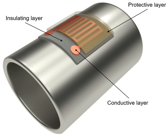
A layer of electrical insulator on the surface of the stainless-steel tube. Its function is to avoid electrical contact between the sensor layer and the tube.
-
An electrically conductive or sensing layer, which is the RTD itself. This metallic layer has a varied electrical resistance as the temperature changes.
-
A protective layer to protect the sensor layer from degradation phenomena such as high-temperature oxidation.
2. Design of the Sensor Layer
3. Base Materials
4. Isolation Layer
References
- Mathur, S.; Gosnell, G.; Sovacool, B.K.; Del Rio, D.D.F.; Griffiths, S.; Bazilian, M.; Kim, J. Industrial decarbonization via natural gas: A critical and systematic review of developments, socio-technical systems and policy options. Energy Res. Soc. Sci. 2022, 90, 102638.
- Yue, K.; Shen, Y. An overview of disruptive technologies for aquaculture. Aquac. Fish. 2021, 7, 111–120.
- Kumar, S.; Baalisampang, T.; Arzaghi, E.; Garaniya, V.; Abbassi, R.; Salehi, F. Synergy of green hydrogen sector with offshore industries: Opportunities and challenges for a safe and sustainable hydrogen economy. J. Clean. Prod. 2023, 384, 135545.
- Islam, M.T.; Nabi, M.; Arefin, M.; Mostakim, K.; Rashid, F.; Hassan, N.; Rahman, S.; McIntosh, S.; Mullins, B.; Muyeen, S. Trends and prospects of geothermal energy as an alternative source of power: A comprehensive review. Heliyon 2022, 8, e11836.
- Javaid, M.; Haleem, A.; Khan, I.H.; Suman, R. Understanding the potential applications of Artificial Intelligence in Agriculture Sector. Adv. Agrochem. 2023, 2, 15–30.
- Bhuiyan, E.A.; Hossain, Z.; Muyeen, S.; Fahim, S.R.; Sarker, S.K.; Das, S.K. Towards next generation virtual power plant: Technology review and frameworks. Renew. Sustain. Energy Rev. 2021, 150, 111358.
- Vandrangi, S.K.; Lemma, T.A.; Mujtaba, S.M.; Ofei, T.N. Developments of leak detection, diagnostics, and prediction algorithms in multiphase flows. Chem. Eng. Sci. 2021, 248, 117205.
- Jayawickrema, U.; Herath, H.; Hettiarachchi, N.; Sooriyaarachchi, H.; Epaarachchi, J. Fibre-optic sensor and deep learning-based structural health monitoring systems for civil structures: A review. Measurement 2022, 199, 111543.
- Djeddi, A.Z.; Hafaifa, A.; Hadroug, N.; Iratni, A. Gas turbine availability improvement based on long short-term memory networks using deep learning of their failures data analysis. Process. Saf. Environ. Prot. 2021, 159, 1–25.
- Hidalgo-Mompeán, F.; Fernández, J.F.G.; Cerruela-García, G.; Márquez, A.C. Dimensionality analysis in machine learning failure detection models. A case study with LNG compressors. Comput. Ind. 2021, 128, 103434.
- Wang, X.; Lin, L.; Lu, S.; Zhang, L.; Li, B.; Zhang, D.; Luo, Y. Evaluation of embedded buckypaper sensors in composite overwrappedped pressure vessels for progressive damage monitoring. Compos. Struct. 2022, 284, 115223.
- Zhang, P.; Gao, D.; Lu, Y.; Ma, Z.; Wang, X.; Song, X. Cutting tool wear monitoring based on a smart toolholder with embedded force and vibration sensors and an improved residual network. Measurement 2022, 199, 111520.
- Kausar, A.Z.; Reza, A.W.; Saleh, M.U.; Ramiah, H. Energizing wireless sensor networks by energy harvesting systems: Scopes, challenges and approaches. Renew. Sustain. Energy Rev. 2014, 38, 973–989.
- Aalsalem, M.Y.; Khan, W.Z.; Gharibi, W.; Khan, M.K.; Arshad, Q. Wireless Sensor Networks in oil and gas industry: Recent advances, taxonomy, requirements, and open challenges. J. Netw. Comput. Appl. 2018, 113, 87–97.
- Virk, M.-U.A.; Mysorewala, M.F.; Cheded, L.; Aliyu, A. Review of energy harvesting techniques in wireless sensor-based pipeline monitoring networks. Renew. Sustain. Energy Rev. 2022, 157, 112046.
- Cho, S.H.; Suh, J.M.; Jeong, B.; Lee, T.H.; Choi, K.S.; Eom, T.H.; Kim, T.; Jang, H.W. Fast responding and highly reversible gasochromic H2 sensor using Pd-decorated amorphous WO3 thin films. Chem. Eng. J. 2022, 446, 136862.
- Li, T.; Shi, T.; Tang, Z.; Liao, G.; Han, J.; Duan, J. Temperature monitoring of the tool-chip interface for PCBN tools using built-in thin-film thermocouples in turning of titanium alloy. J. Mater. Process. Technol. 2019, 275, 116376.
- Wang, H.; Rajamani, R. A remote position sensing method based on passive high magnetic permeability thin films. Sens. Actuators A Phys. 2019, 295, 217–223.
- Kim, J.; Kim, J.; Shin, Y.; Yoon, Y. A study on the fabrication of an RTD (resistance temperature detector) by using Pt thin film. Korean J. Chem. Eng. 2001, 18, 61–66.
- Shao, L.; Zhao, X.; Gu, S.; Ma, Y.; Liu, Y.; Deng, X.; Jiang, H.; Zhang, W. Pt thin-film resistance temperature detector on flexible Hastelloy tapes. Vacuum 2020, 184, 109966.
- Sim, J.K.; Hyun, J.; Doh, I.; Ahn, B.; Kim, Y.T. Thin-film resistance temperature detector array for the measurement of temperature distribution inside a phantom. Metrologia 2017, 55, L5–L11.
- Han, J.; Cheng, P.; Wang, H.; Zhang, C.; Zhang, J.; Wang, Y.; Duan, L.; Ding, G. MEMS-based Pt film temperature sensor on an alumina substrate. Mater. Lett. 2014, 125, 224–226.
- Zhai, Y.; Cai, C.; Huang, J.; Liu, H.; Zhou, S.; Liu, W. Study on the Resistance Characteristic of Pt Thin Film. Phys. Procedia 2012, 32, 772–778.
- Phatthanakun, R.; Deekla, P.; Pummara, W.; Sriphung, C.; Pantong, C.; Chomnawang, N. Design and fabrication of thin-film aluminum microheater and nickel temperature sensor. In Proceedings of the 2012 7th IEEE International Conference on Nano/Micro Engineered and Molecular Systems (NEMS), Kyoto, Japan, 5–8 March 2012; pp. 112–115.
- Santos, E.J.; Vasconcelos, I.B. RTD-based smart temperature sensor: Process development and circuit design. In Proceedings of the 2008 26th International Conference on Microelectronics, Nis, Serbia, 11–14 May 2008; pp. 333–336.
- Pacardo, D.B.; Neupane, B.; Wang, G.; Gu, Z.; Walker, G.M.; Ligler, F.S. A temperature microsensor for measuring laser-induced heating in gold nanorods. Anal. Bioanal. Chem. 2014, 407, 719–725.
- Turkani, V.S.; Maddipatla, D.; Narakathu, B.B.; Altay, B.N.; Fleming, D.; Bazuin, B.J.; Atashbar, M.Z. A Screen-Printed Nickel Based Resistance Temperature Detector (RTD) on Thin Ceramic Substrate. In Proceedings of the 2020 IEEE International Conference on Electro Information Technology (EIT), Chicago, IL, USA, 31 July–1 August 2020; pp. 577–580.
- Martinez-Quijada, J.; Caverhill-Godkewitsch, S.; Reynolds, M.; Gutierrez-Rivera, L.; Johnstone, R.; Elliott, D.; Sameoto, D.; Backhouse, C. Fabrication and characterization of aluminum thin film heaters and temperature sensors on a photopolymer for lab-on-chip systems. Sens. Actuators A Phys. 2013, 193, 170–181.
- Stankevič, V.; Šimkevičius, Č. Application of aluminum films as temperature sensors for the compensation of output thermal shift of silicon piezoresistive pressure sensors. Sens. Actuators A Phys. 1998, 71, 161–166.
- Kim, S.-Y.; Kim, J.-D.; Kim, Y.-S.; Song, H.-J.; Park, C.-Y. Resistance Temperature Detector Sensor with a Copper Pattern on the Printed Circuit Board. Int. J. Control. Autom. 2015, 8, 67–74.
- Namisnak, L.H.; Khoshnevis, S.; Diller, K.R. A Conformable Two-Dimensional Resistance Temperature Detector for Measuring Average Skin Temperature. J. Med. Devices 2021, 15, 031010.
- Souza, A.L.R.; Correa, M.A.; Bohn, F.; Castro, H.; Fernandes, M.M.; Vaz, F.; Ferreira, A. High Performance of Metallic Thin Films for Resistance Temperature Devices with Antimicrobial Properties. Sensors 2022, 22, 7665.
- Santi, W.N.; Toifur, M. Analysis of Micro Structure and the Resistivity of Cu / Ni Thin Coat as a Low Temperature Sensor Using Electroplating Method Assisted with Magnetic Field outside of the Ion Flow. Key Eng. Mater. 2021, 885, 141–147.
- Mehmood, Z.; Mansoor, M.; Haneef, I.; Ali, S.Z.; Udrea, F. Evaluation of thin film p-type single crystal silicon for use as a CMOS Resistance Temperature Detector (RTD). Sens. Actuators A Phys. 2018, 283, 159–168.
- Navarro, A.; Lechner, M.; Ruiz, U.; Lopez, A. Sensitivity analysis of the Expansion Process for Alloy UNS N08028. MATEC Web Conf. 2016, 80, 10005.
- Garcia-Martin, J.; González-Fernández, R.; Calleja-Saenz, B.; Ferreño-Blanco, D. Measurement of hardness increase for shot-peened austenitic TX304HB stainless steel tubes with electromagnetic Non-Destructive testing. Measurement 2019, 149, 106925.
- Bartzsch, H.; Glöß, D.; Böcher, B.; Frach, P.; Goedicke, K. Properties of SiO2 and Al2O3 films for electrical insulation applications deposited by reactive pulse magnetron sputtering. Surf. Coatings Technol. 2003, 174–175, 774–778.
- Martinez-Perdiguero, J.; Mendizabal, L.; Morant-Miñana, M.C.; Castro-Hurtado, I.; Juarros, A.; Ortiz, R.; Rodriguez, A. Electrical insulation and breakdown properties of SiO2 and Al2O3 thin multilayer films deposited on stainless steel by physical vapor deposition. Thin Solid Films 2015, 595, 171–175.
- Liu, H.; Jiang, S.; Zhao, X.; Jiang, H.; Zhang, W. YSZ/Al2O3 multilayered film as insulating layer for high temperature thin film strain gauge prepared on Ni-based superalloy. Sens. Actuators A Phys. 2018, 279, 272–277.
- Djugum, R.; I Jolic, K. A fabrication process for vacuum-deposited strain gauges on thermally sprayed Al2O3. J. Micromechanics Microengineering 2006, 16, 457–462.
- Li, Y.-Q.; Yu, Z.-N.; Leng, J.; Zhang, D.-P.; Chen, S.; Jin, G. Electrical insulation and bending properties of SiOx barrier layers prepared on flexible stainless steel foils by different preparing methods. Thin Solid Films 2011, 519, 4234–4238.
- Advanced Coating Technology—Tubacoat. Available online: https://www.tubacoat.com/ (accessed on 16 September 2022).
- Shabareesh, N. TUBACOAT—An Efficient and Cost Effective Advanced Coating Solution for Tubular Products in Extreme Refinery and Petrochemical Applications, Presented at the Refcomm, Mumbai, 2019. Available online: https://refiningcommunity.com/wp-content/uploads/2019/08/118-An-Efficient-and-Cost-Effective-Advanced-Coating-Solution-for-Tubular-Products-in-Extreme-Refinery-and-Petrochemical-Applications-Tubacex-Group-DCU-Mumbai-2019.pdf (accessed on 22 March 2021).