Your browser does not fully support modern features. Please upgrade for a smoother experience.
Please note this is a comparison between Version 2 by Camila Xu and Version 1 by Nunzio Cennamo.
The research asks for meta-changes. As an example, a paradigm change in the use of the plasmonic phenomena produces innovative sensors. In particular, the sensor systems based on this innovative sensing approach were designed, fabricated, and investigated to assess their ability to measure various physical features, such as magnetic field, temperature, force, and volume, and to realize chemical sensors.
- surface plasmon resonance (SPR)
- multimode waveguides
- multimode optical fibers
- optical fiber sensors
1. Introduction
Optical sensors have been developed recently using several sensing principles, such as photonic crystals, which are an attractive sensing approach for realizing optical sensors and biosensors [1,2,3][1][2][3]. However, these types of sensors require expensive technologies to develop them.
In recent years, the Surface Plasmon Resonance phenomenon has achieved a lot of importance in different application fields. This is a highly sensitive technique that allows the measurement of a small refractive index variation at the boundary between a metallic layer and an encompassing dielectric medium. Once the resonance conditions are verified, a dip in the output signal, as a consequence of a strong absorption, can be observed. The dip is achieved at a particular wavelength, called the resonance wavelength, and it is linked to the refractive index at the boundary [4,5,6,7,8][4][5][6][7][8]. This technique can be paired with optical waveguides, such as optical fibers, to attain sundry sensor systems for several application areas [9,10,11,12,13][9][10][11][12][13]. These types of sensors have important advantages, such as low cost, rapid response, immunity to electromagnetic interference, high sensitivity, and small size.
In particular, the SPR sensor can be used as a refractometer, a bio/chemical sensor by functionalizing the surface with a particular receptor, a pressure sensor, and so on [14,15,16,17,18,19,20][14][15][16][17][18][19][20]. Generally, the sensor system based on the SPR can be realized by using different types of optical waveguides, such as monomodal or multimodal. Thanks to the properties of the multimodal waveguides, the SPR technique can be exploited more efficiently, and, for this reason, multimodal waveguides are widely adopted for optical sensors [12]. In more detail, when dealing with multimodal waveguides, the dip, caused by the SPR phenomenon, is wider when compared with that caused by the monomodal waveguides. This phenomenon is a consequence of a convolution of diverse propagating modes, each of which is linked to a distinct angle of incidence at the metal–dielectric interface [12,21][12][21]. In such a case, despite broader SPR spectra being obtained, a greater sensitivity is achieved as well, thus leading to an overall performance improvement [12].
32. Physical Sensing
32.1. Magnetic Field Sensor
The magnetic field sensor is realized by using a POF patch, with a core diameter of 500 μm, paired with the SPR-POF sensor. To make the patch sensitive to the change in the magnetic field, it is coated with a ferrofluid along 20 mm of its length [23][22]. To modify the mode profile of the input light, a magnet is used, since, by tuning the distance from the sensitive patch, it is possible to change the value of the bending force on the patch covered with ferrofluid. The distance between the magnet and the sensitive patch can be regulated by a special holder, as schematically reported in Figure 21.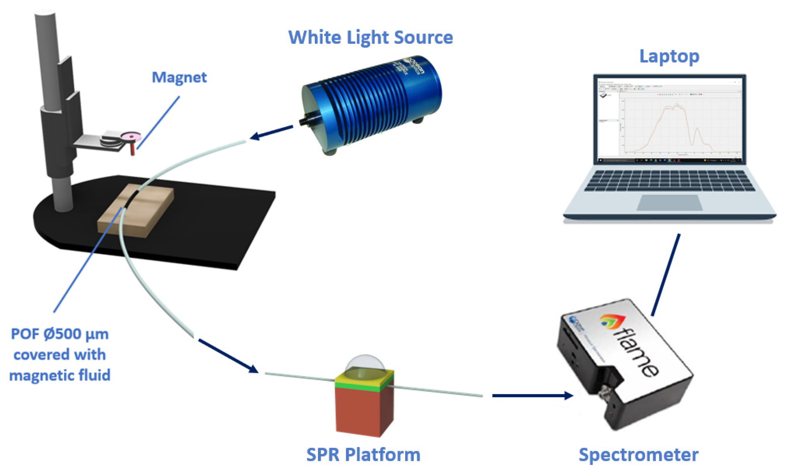
Figure 21. Outline of the magnetic field sensor system. A special holder is utilized to tune the distance between the magnet and the ferrofluidic-covered patch.
Table 1.
A comparison of several magnetic field sensors based on different sensing methods.
| Sensing Method | Sensitivity (pm/mT) | Resolution (mT) | Ref. |
|---|---|---|---|
| Based on altering the plasmonic conditions in multimode SPR-POF platform | 6800 | 0.029 | [23][22] |
| Based on a magnetic fluid as surrounding medium of a plasmonic optical-fiber-based platform | 3000 | - | [24][23] |
| Based on a magnetic fluid as surrounding medium of a plasmonic optical-fiber-based platform | 10,000 | 0.5 | [25][24] |
| Based on a magnetic fluid as surrounding medium of a plasmonic optical-fiber-based platform | 870 | - | [26][25] |
3.2. Temperature Sensor
2.2. Temperature Sensor
The temperature sensor system includes two D-shaped-POF probes which are coupled in a sequence: the first platform is characterized by a coating of thermosensitive material on the exposed POF core to make it responsive to temperature changes, while the second one consists of an SPR-POF probe [27][26]. The POF used for the realization of both the platforms is multimodal, with a 1 mm diameter. The production process of the thermosensitive platform can be summarized as follows. First, the POF is fixed with glue onto a physical support, and then it is polished with two types of lapping sheets (5 and 1 μm grits) in order to obtain the D-shaped area. On the modified POF, a layer of thermosensitive material is then deposited. For this purpose, silicone is used since its physical characteristics are dependent on the temperature [28][27]. As a proof of concept to realize the thermal POF sensor chip, an adhesive tape with a nominal thickness of 70 μm is used to control the thickness of the silicone layer. More specifically, by exploiting the adhesive tape, a channel is achieved by fixing two pieces of adhesive tape at the end of the physical support. After this, the silicone is placed on the exposed POF’s core by exploiting a spatula to level the silicone layer at the adhesive tape thickness. In this way, a silicone thickness of 70 μm is obtained. This simple approach offers the ability to realize thermal sensor chips with good reproducibility. The sensor’s performances can be changed by using a different thickness of the silicone layer. The presented sensor system is tested by tuning the temperature of the water deposited on the thermosensitive platform to induce a change in the physical characteristics and, consequently, in the refractive index, of the silicone layer [28][27]. During the test, the refractive index of the solution upon the SPR D-shaped platform is fixed at 1.332 (water), and the temperature of the solution upon the thermosensitive platform varies from 20 °C to 38 °C, with a step size of 3 °C. More details about this temperature sensor are extensively reported in [27][26]. An analysis, reported in Table 2, is performed to compare the presented temperature sensor platform with other configurations already presented in the literature.Table 2.
A comparison of several temperature sensors based on different sensing methods.
| Sensing Method | Linear Range (°C) | Resolution (°C) | Ref. |
|---|---|---|---|
| Based on altering the plasmonic conditions in multimode SPR-POF platform |
20–38 | 1.2 | [27][26] |
| Based on a fiber optic displacement platform | 42–90 | 2.4 | [29][28] |
| Based on a Fabry–Perot interferometer | - | 1 | [30][29] |
| Based on plasmonic phenomenon in optical fibers | 30–70 | 0.8 | [31][30] |
3.3. Force Sensor
2.3. Force Sensor
The force sensor system is realized by using a 1 mm POF patch immobilized into a 3D-printed support through two clamps and representing the force sensing region. The force sensitive patch is then coupled to an SPR-POF probe in a series. The holder, reported in Figure 72, is devised and successively produced by means of a 3D printer (Photon Mono X, Anycubic®, Shenzhen, China) [32][31].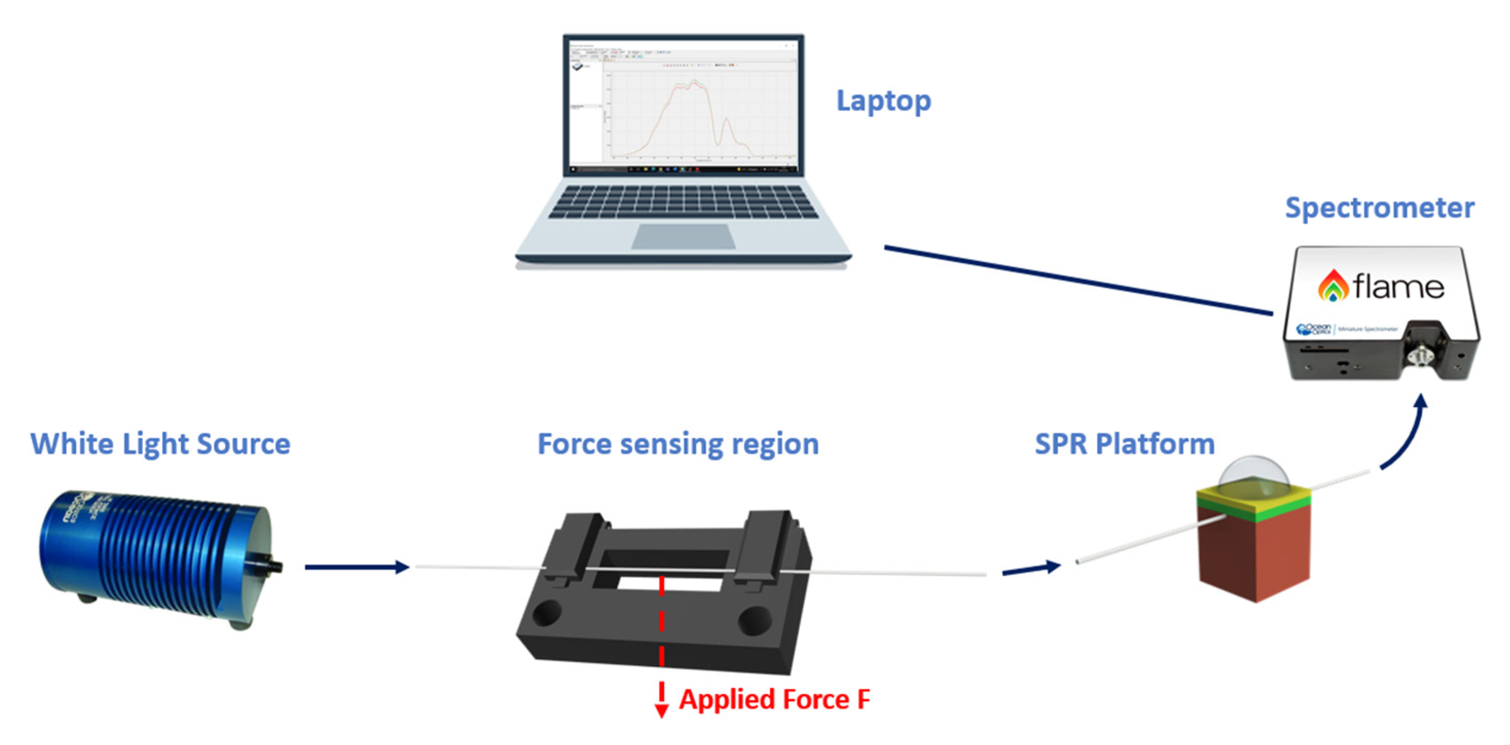
Figure 72.
A schematization of the force sensor system.
Table 3.
A comparison of several force sensors based on different sensing methods.
3. Outline of the micro-volume liquid sensor system.
In the end, a comparative analysis is reported in Table 4, where the presented sensor system is compared with two volume liquid sensors, already presented in the literature, in terms of resolution.
Table 4.
A comparison of several volume sensors based on different sensing methods.
3.4. Micro-Liquid Volume Sensor
2.4. Micro-Liquid Volume Sensor
The micro-liquid volume sensor system consists of a patch of light diffusive fiber (LDF). In LDFs, the light is spread from the core, and it is diffused toward the external medium thanks to the scattering centers present in their core. The used LDF-POF is fixed in a 3D-printed tank in order to realize the volume-sensing region, and it is coupled in a sequence with an SPR-POF probe [36][35]. The tank, highlighted in the outline of the micro-liquid sensor system in Figure 93, is printed using a 3D printer (Photon Mono X, Anycubic, Shenzhen, China), and its aim is to hold the micro-liquid volume around the fiber. The patch consists of a 1600 μm uncladded LDF-POF (manufactured by Global Engineering Network, Dosson di Casier, Italy) with a removable jacket of approximately 400 μm (total diameter 2 mm). The jacket is stripped off by a mechanical tool along 1 cm of its length; this piece of fiber without jackets represents the volume-sensitive area, and it is fixed in the tank through two holes using white silicone [36][35].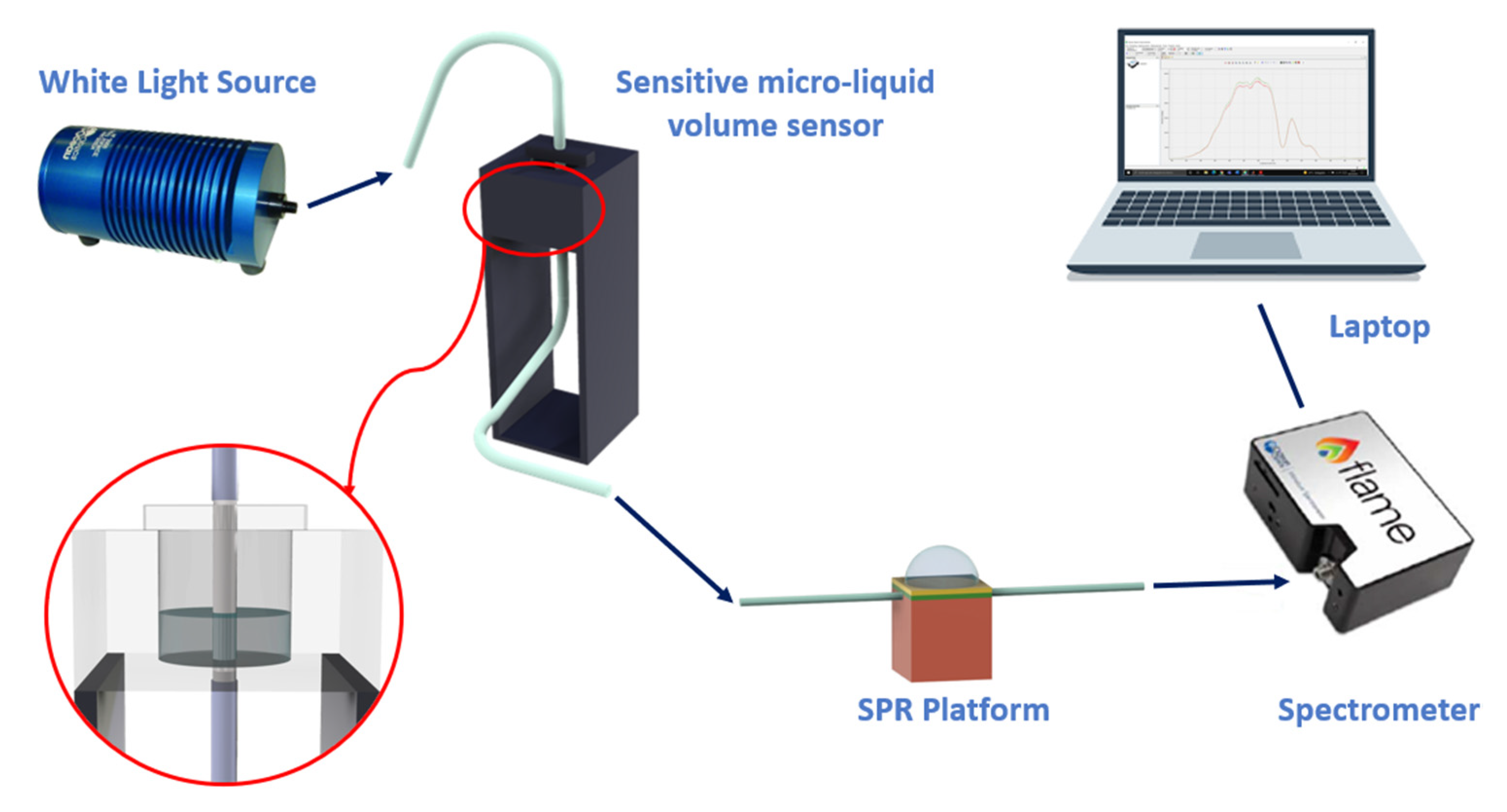
Figure 9
References
- Parandin, F.; Heidari, F.; Rahimi, Z.; Olyaee, S. Two-Dimensional photonic crystal Biosensors: A review. Opt. Laser Technol. 2021, 144, 107397.
- Giden, I.H. Photonic crystal based interferometric design for label-free all-optical sensing applications. Opt. Express 2022, 30, 21679.
- Jokar, M.H.; Naraghi, A.; Seifouri, M.; Olyaee, S. Photonic crystal bio-sensor for highly sensitive label-free detection of cancer cells. Opt. Quantum Electron. 2023, 55, 660.
- Butt, M.A.; Khonina, S.N.; Kazanskiy, N.L. Plasmonics: A necessity in the field of sensing—A review. Fiber Integr. Opt. 2021, 40, 14–47.
- Liu, L.; Yang, J.; Yang, Z.; Wan, X.; Hu, N.; Zheng, X. Theoretical analysis of the optical propagation characteristics in a fiber-optic surface plasmon resonance sensor. Sensors 2013, 13, 7443–7453.
- Homola, J. Surface plasmon resonance sensors for detection of chemical and biological species. Chem. Rev. 2008, 108, 462–493.
- Mejía-Salazar, J.R.; Oliveira, O.N., Jr. Plasmonic sensing: Focus review. Chem. Rev. 2018, 118, 10617–10625.
- Tong, L.; Wei, H.; Zhang, S.; Xu, H. Recent Advances in Plasmonic Sensors. Sensors 2014, 14, 7959–7973.
- Gupta, B.D.; Verma, R.K. Surface plasmon resonance-based fiber optic sensors: Principle, probe designs, and some applications. J. Sens. 2009, 2009, 979761.
- Sharma, A.K.; Jha, R.; Gupta, B.D. Fiber-optic sensors based on surface plasmon resonance: A comprehensive review. IEEE Sens. J. 2007, 7, 1118–1129.
- Klantsataya, E.; Jia, P.; Ebendorff-Heidepriem, H.; Monro, T.; François, A. Plasmonic fiber optic refractometric sensors: From conventional architectures to recent design trends. Sensors 2017, 17, 12.
- Kanso, M.; Cuenot, S.; Louarn, G. Sensitivity of optical fiber sensor based on surface plasmon resonance: Modeling and experiments. Plasmonics 2008, 3, 49–57.
- Mitsushio, M.; Miyashita, K.; Higo, M. Sensor properties and surface characterization of the metal-deposited SPR optical fiber sensors with Au, Ag, Cu, and Al. Sens. Actuat. A Phys. 2006, 125, 296–303.
- Zhao, Y.; Tong, R.J.; Xia, F.; Peng, Y. Current status of optical fiber biosensor based on surface plasmon resonance. Biosens. Bioelectron. 2019, 142, 111505.
- Zhao, Y.; Wu, Q.L.; Zhang, Y.N. Simultaneous measurement of salinity, temperature and pressure in seawater using optical fiber SPR sensor. Measurement 2019, 148, 106792.
- Velázquez-González, J.S.; Monzón-Hernández, D.; Moreno-Hernández, D.; Martínez-Piñón, F.; Hernández-Romano, I. Simultaneous measurement of refractive index and temperature using a SPR-based fiber optic sensor. Sens. Actuat. B Chem. 2017, 242, 912–920.
- Duarte, D.P.; Alberto, N.; Bilro, L.; Nogueira, R. Theoretical design of a high sensitivity SPR-based optical fiber pressure sensor. J. Light. Technol. 2015, 33, 4606–4611.
- Singh, A.K.; Mittal, S.; Das, M.; Saharia, A.; Tiwari, M. Optical biosensors: A decade in review. Alex. Eng. J. 2023, 67, 673–691.
- Shrivastav, A.M.; Mishra, S.K.; Gupta, B.D. Fiber optic SPR sensor for the detection of melamine using molecular imprinting. Sens. Actuat. B Chem. 2015, 212, 404–410.
- Pollet, J.; Delport, F.; Janssen, K.P.F.; Tran, D.T.; Wouters, J.; Verbiest, T.; Lammertyn, J. Fast and accurate peanut allergen detection with nanobead enhanced optical fiber SPR biosensor. Talanta 2011, 83, 1436–1441.
- Dwivedi, Y.S.; Sharma, A.K.; Gupta, B.D. Influence of design parameters on the performance of a surface plasmon sensor based fiber optic sensor. Plasmonics 2008, 3, 79–86.
- Cennamo, N.; Arcadio, F.; Marletta, V.; Baglio, S.; Zeni, L.; Andò, B. A magnetic field sensor based on SPR-POF platforms and ferrofluids. IEEE Trans. Instrum. Meas. 2020, 70, 9504010.
- Zhou, X.; Li, X.; Li, S.; An, G.-W.; Cheng, T. Magnetic field sensing based on SPR optical fiber sensor interacting with magnetic fluid. IEEE Trans. Instrum. Meas. 2019, 68, 234–239.
- Rodríguez-Schwendtner, E.; Díaz-Herrera, N.; Navarrete, M.C.; González-Cano, A.; Esteban, Ó. Plasmonic sensor based on tapered optical fibers and magnetic fluids for measuring magnetic fields. Sens. Actuat. A Phys. 2017, 264, 58–62.
- Liu, H.; Li, H.; Wang, Q.; Wang, M.; Ding, Y.; Zhu, C.; Cheng, D. Temperature-compensated magnetic field sensor based on surface plasmon resonance and directional resonance coupling in a D-shaped photonic crystal fiber. Optik 2018, 158, 1402–1409.
- Cennamo, N.; Del Prete, D.; Arcadio, F.; Zeni, L. A Temperature Sensor Exploiting Plasmonic Phenomena Changes in Multimode POFs. IEEE Sens. J. 2022, 22, 12900–12905.
- Dugas, J.; Michel, P.; Martin, L.; Cariou, J.M. Behavior of the refractive index and of the coefficient of thermal expansion of silicone with temperature. Appl. Opt. 1986, 25, 3807–3808.
- Rahman, H.A.; Harun, S.W.; Saidin, N.; Yasin, M.; Ahmad, H. Fiber optic displacement sensor for temperature measurement. IEEE Sens. J. 2012, 12, 1361–1364.
- Tian, Z.; Yu, Z.; Liu, B.; Wang, A. Sourceless optical fiber high temperature sensor. Opt. Lett. 2016, 41, 195–198.
- Lu, L.; Jiang, Z.; Hu, Y.; Zhou, H.; Liu, G.; Chen, Y.; Luo, Y.; Chen, Z. A portable optical fiber SPR temperature sensor based on a smart-phone. Opt. Express 2019, 27, 25420–25427.
- Arcadio, F.; Zeni, L.; Cennamo, N. Exploiting Plasmonic Phenomena in Polymer Optical Fibers to Realize a Force Sensor. Sensors 2022, 22, 2391.
- Peirs, J.; Clijnen, J.; Reynaerts, D.; Van Brussel, H.; Herijgers, P.; Corteville, B.; Boone, S. A micro optical force sensor for force feedback during minimally invasive robotic surgery. Sens. Actuat. A Phys. 2004, 115, 447–455.
- Ioppolo, T.; Kozhevnikov, M.; Stepaniuk, V.; Volkan Ötügen, M.; Sheverev, V. Micro-optical force sensor concept based on whispering gallery mode resonators. Appl. Opt. 2008, 47, 3009–3014.
- Kulkarni, A.; Na, J.; Kim, Y.J.; Baik, S.; Kim, T. An evaluation of the optical fiber beam as a force sensor. Opt. Fiber Technol. 2009, 15, 131–135.
- Arcadio, F.; Del Prete, D.; Minardo, A.; Marzano, C.; Zeni, L.; Cennamo, N. Micro-liquid volume measurements realized by changing the plasmonic conditions via specialty optical fibers. In Proceeding of the 2022 IEEE International Symposium on Measurements & Networking (M&N), Padua, Italy, 18–20 July 2022.
- Singh, H.K.; Basumatary, T.; Chetia, D.; Bezboruah, T. Fiber Optic Sensor for Liquid Volume Measurement. IEEE Sens. J. 2014, 14, 935–936.
- Hazarika, N.; Roy, R.K.; Singh, H.K.; Bezboruah, T. Investigation on Measurement of Liquid Volume by using Bend Sensor and Linear Extension Spring. In Proceeding of the 2022 IEEE Delhi Section Conference (DELCON), New Delhi, India, 11–13 February 2022.
More