Your browser does not fully support modern features. Please upgrade for a smoother experience.
Please note this is a comparison between Version 2 by Rita Xu and Version 1 by Xuhong Qiang.
In civil engineering, beam structures such as bridges require reinforcement to increase load-bearing capacity and extend service life due to damage, aging, and capacity degradation under long-time services and disasters. The utilization of Fe-based shape memory alloys (Fe-SMA) to reinforce structures has been proven efficient and reliable, and the recovery stress of activated Fe-SMA can satisfy the reinforcement requirements.
- Fe-based shape memory alloys
- shape memory effect
- activation recovery characteristics
1. Introduction
Civil engineering structures, such as bridges, buildings, and high-rise structures, may suffer various defects in the design, production, and construction processes. Under long-term service conditions, they are faced with cracking, rustiness, and aging problems due to overload, corrosion, fatigue, etc. [1,2,3][1][2][3]. Under the action of fire, earthquake, wind, and other disasters, existing structures may also sustain damage and deformation [4,5,6,7][4][5][6][7]. In the United States and Europe, where the infrastructures were constructed earlier, a large number of engineering structures have been suffering aging problems and require reinforcement and maintenance. Although the prosperous infrastructure construction in China started late, increasing demands for structural reinforcement are emerging, which contains great scientific research value and economic prospects. The beam, an essential and fundamental component of structures, plays a crucial role in achieving the spanning, bearing, and linking functions. Therefore, it is of considerable value to strengthen and repair the deteriorated beams in existing structures to ensure their bearing capacity and prolong their service life.
Shape memory alloys (SMAs), as a new intelligent material, have been widely used in aerospace, robotics, medicine, and other fields, possessing two typical characteristics: shape memory effect (SME) and superelasticity (SE) [8,9,10,11][8][9][10][11]. SMAs contain two different composition phases: austenite and martensite. The phase transformation between austenite and martensite, which is induced by changes in temperatures or stresses, is referred to as the martensite transformation [12,13,14][12][13][14]. The martensite transformation is a diffusionless and solid-state phase transition, in which the atoms move cooperatively. It differs from the plastic deformation of normal metal materials, which is due to the dislocations of crystals slip [15]. Thus, the martensite transformation is a reversible process, and the characteristics of SME and SE benefit from this peculiarity. In civil engineering, SE is mainly used in structural seismic resistance and energy dissipation. SMA can be manufactured into basic components (wire, bar, spring, etc.) and key components (dampers, supports, isolation devices, etc.) [16,17,18,19][16][17][18][19]. SME can be used for structural reinforcement and enhancement. The recovery stress generated by activating SMA can introduce prestress based on increasing the stiffness of structures [20,21,22][20][21][22].
Retrospectively, the shape memory materials were first discovered in the gold–cadmium (Au-Cd) alloys by Arne Ölander in 1932 [23]. Decades later, the reversible phase transformation of SME, governed by the thermoelastic martensite phase of Au-Cd alloys, was reported by Kurdjumov and Khandros in 1949, and by Chang and Read in 1951 [24,25][24][25]. In the 1960s, Buehler et al. found the SME of nickel–titanium (Ni-Ti) alloys in shock absorption tests [26]. In the 1970s, Otsuka et al. found that the shape memory effect of Cu-Al-Ni alloys was closely related to the thermoelastic martensite transformation [27]. In the early 1980s, Sato et al. first studied the SME of Fe-Mn-Si alloys [28,29][28][29].
NiTi-SMA and Fe-SMA are the two SMAs appropriately employed in civil engineering. The shape recovery ability of Fe-SMA is weaker than that of NiTi-SMA, but it also possesses high strength, excellent plasticity, and good forming properties [30,31][30][31]. Furthermore, its lower production costs compared to NiTi-SMA make it more economical for large-scale application in the field of structural reinforcement [32]. After thermal activation, Fe-SMA can realize the active control of structural stiffness and deformation, as well as repair local damage and cracks of structures [33,34][33][34]. Due to SME, no complex tension devices are required to achieve pretension, which eliminates the restriction on operating spaces and improves the convenience of construction [35].
2. Material Properties of Fe-SMA
2.1. Introduction of Fe-Mn-Si Alloys
Overall, Fe-SMA contains three types of crystal structures, as shown in Figure 1, which are the face-centered cubic lattice of austenite phase (fcc, γ-austenite), the body-centered tetragonal lattice of martensite phase (bct, α′-martensite), and the hexagonal close-packed lattice of martensite phase (hcp, ε-martensite).
Figure 1. Crystal phase of Fe-SMA: (a) γ-austenite (fcc), (b) α′-martensite (bct), (c) ε-martensite (hcp).
Table 1. The most significant Fe-Mn-Si alloys in the development history.
| Stage | Alloys (Composition in Mass %) | Year | References |
|---|---|---|---|
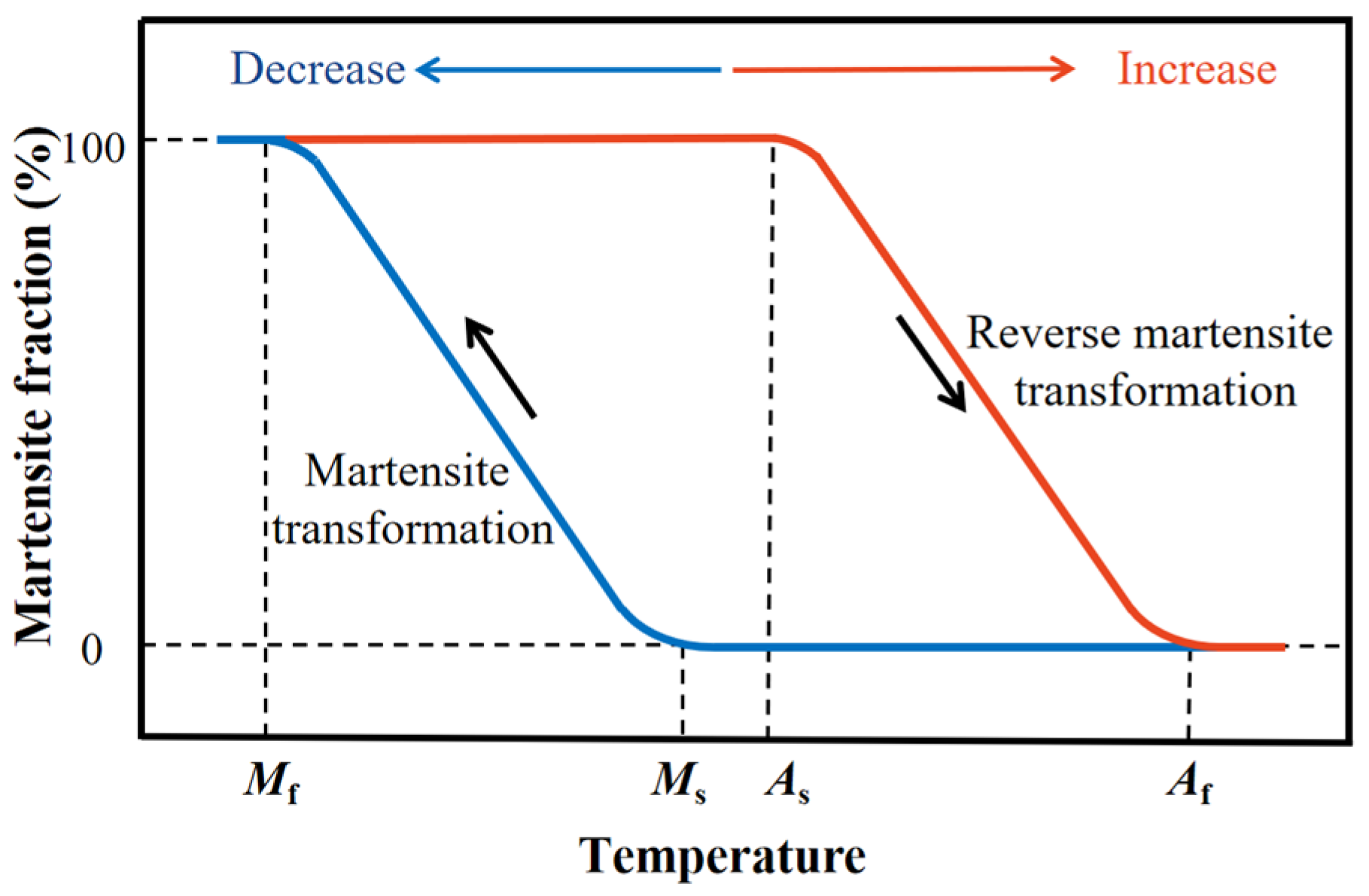
Figure 2. Schematic definition of characteristic temperatures in martensite transformation.
Table 2. Martensite transformation temperatures of Fe-SMA.
| Alloys | Mf | (°C) | Ms | (°C) | As | (°C) | Af | (°C) | Refs. |
|---|---|---|---|---|---|---|---|---|---|
| First stage: optimization of alloy elements |
Fe-30Mn-1Si | 1982 | [28] | ||||||
| Fe-30Mn-1Si | — | 27 | 127 | — | [28] | ||||
| Fe-30Mn-6Si | 1984 | [29] | |||||||
| Fe-28Mn-6Si-5Cr | — | 20 | 120 | 180 | [64] | Fe-32Mn-6Si | 1986 | [58] | |
| Fe-14Mn-6Si-9Cr-5Ni | — | 20 | 70 | 300 | [65] | Fe-28Mn-6Si-5Cr | 1990 | [48] | |
| Fe-17Mn-5Si-10Cr-4Ni-1(V,C) | −90 | −75Fe-20Mn-5Si-8Cr-5Ni | |||||||
| 85 | 110 | [ | 57 | ] | |||||
| Fe-17Mn-5Si-10Cr-4Ni-1(V,C) | −64 | −60Fe-16Mn-5Si-12Cr-5Ni | |||||||
| 103 | 162 | [ | 66 | ] | |||||
| Fe-19Mn-4Si-8Cr-4Ni-0.01C | −100 | −38 | 138 | 218Fe-30Mn-6Si | 1995 | [54] | |||
| [ | 35 | ] | Fe-28Mn-6Si-5Cr | 2001 | [46] | ||||
| Fe-18Mn-8Cr-4Si-2Ni-0.36Nb-0.36N | |||||||||
| Fe-30Mn-6Si | 2002 | [51] | |||||||
| Fe-30Mn-6Si-5Cr | |||||||||
| [ | 82 | ] | Fe-13Mn-5Si-12Cr-5Ni | ||||||
| Fe-25Mn-6Si-5Cr-0.14N | 2006 | [53] | |||||||
| Second stage: introduction of fine precipitates |
Fe-28Mn-6Si-5Cr-0.5(Nb,C) | 2001 | [55] | ||||||
| Fe-28Mn-6Si-5Cr-1(V,N) | 2004 | [56] | |||||||
| Fe-15Mn-5Si-9Cr-5Ni-(0.5-1.5)NbC | 2005 | [59] | |||||||
| Fe-28Mn-6Si-5Cr-0.53Nb-0.06C | 2006 | [60] | |||||||
| Fe-14Mn-5Si-8Cr-4Ni-0.16C | 2007 | [61] | |||||||
| Fe-17Mn-5Si-10Cr-4Ni-1(V,C) | 2009 | [57] | |||||||
| Fe-16Mn-5Si-10Cr-4Ni-1(V,N) | 2013 | [44] | |||||||
| Fe-19Mn-4Si-8Cr-4Ni-0.01C | 2021 | [35] |
2.2. SME and Activation Recovery Performance
The SME is the result of the reversible martensite transformation [12]. The corresponding relationship between the temperature and martensite fractions is depicted in Figure 2. There are four characteristic temperatures in the transformation process from low to high: martensite finish temperature (Mf), martensite start temperature (Ms), austenite start temperature (As), and austenite finish temperature (Af). The martensite transformation from fcc (γ-austenite) to hcp (ε-martensite) is induced when the temperature decreases lower than Ms. The martensite fraction increases with the decreasing temperature, and the martensite transformation is completed until the temperature is below Mf. Adversely, the reverse transformation from hcp (ε-martensite) to fcc (γ-austenite) is induced when the temperature increases beyond As and the martensite fraction decreases until the reverse transformation is completed with the temperature higher than Af [62,63][62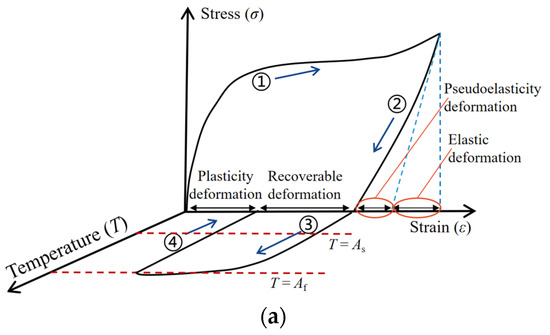
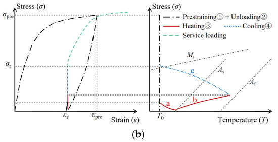
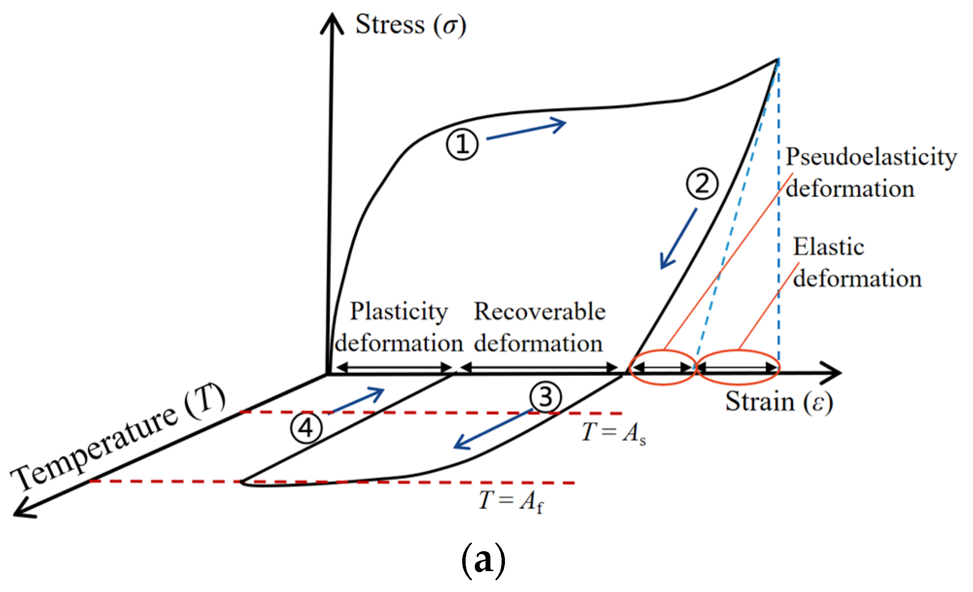
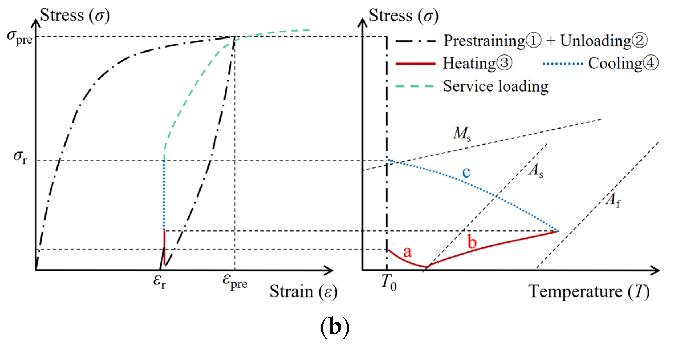
Figure 3. SME and activation performance of Fe-SMA: (a) SME, (b) activation performance.
3. Mechanical Performance of Fe-SMA
3.1. Basic Mechanical Properties
When applied in practice, Fe-SMA materials can be manufactured into various shapes and sizes, such as rods, bars, and strips [70[70][71][72],71,72], as shown in Figure 4. As an alloy, the basic properties of Fe-SMA are similar to those of steel. The physical properties of Fe-SMA, steel, and concrete are summarized in Table 3. Their thermal expansion coefficients are numerically close, and the three materials can deform collaboratively when the temperature changes; hence, Fe-SMA has prominent advantages in strengthening steel and concrete structures [73,74,75][73][74][75].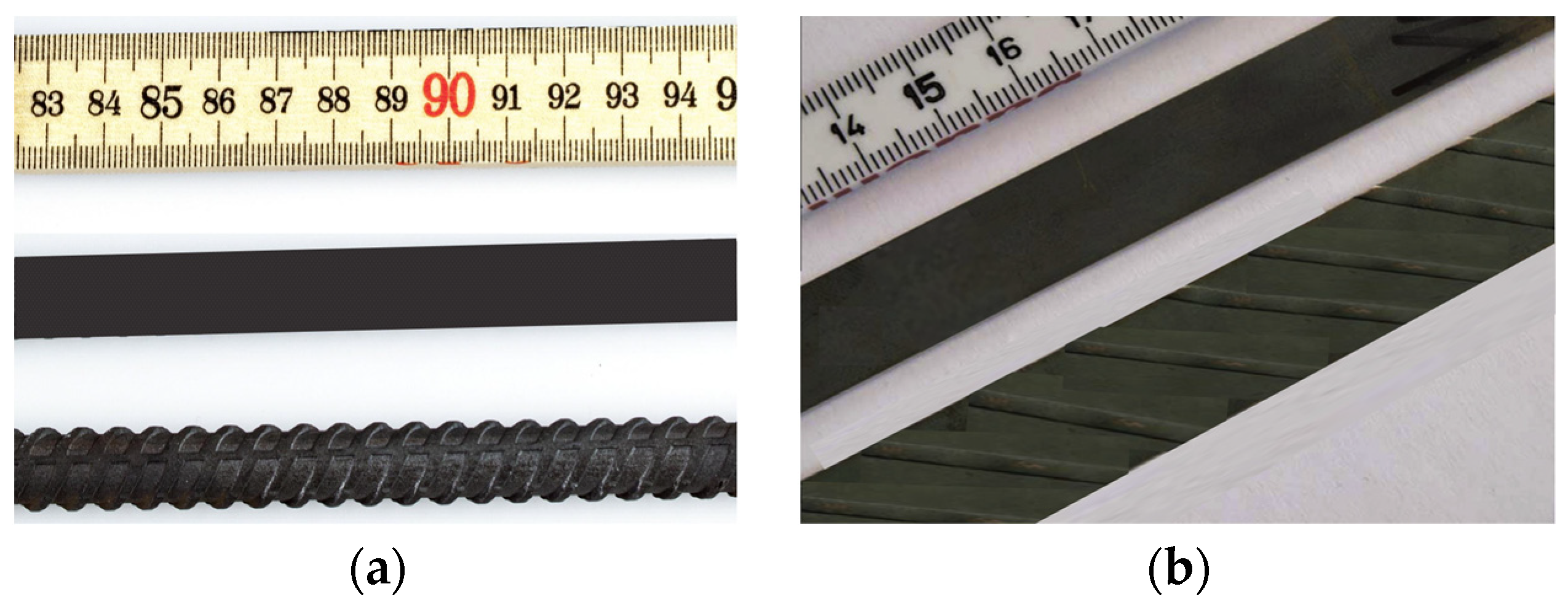
Figure 4. Schematic diagram of Fe-SMA: (a) Fe-SMA bars, (b) Fe-SMA strips.
Table 3. Physical parameters of Fe-SMA, steel, and concrete.
| Materials | Density (kg/m | 3 | ) | Elastic Modulus (GPa) |
Thermal Expansion (K | −1 | ) | Poisson Ratio | Elongation (%) |
Ultimate Strength (MPa) |
|---|
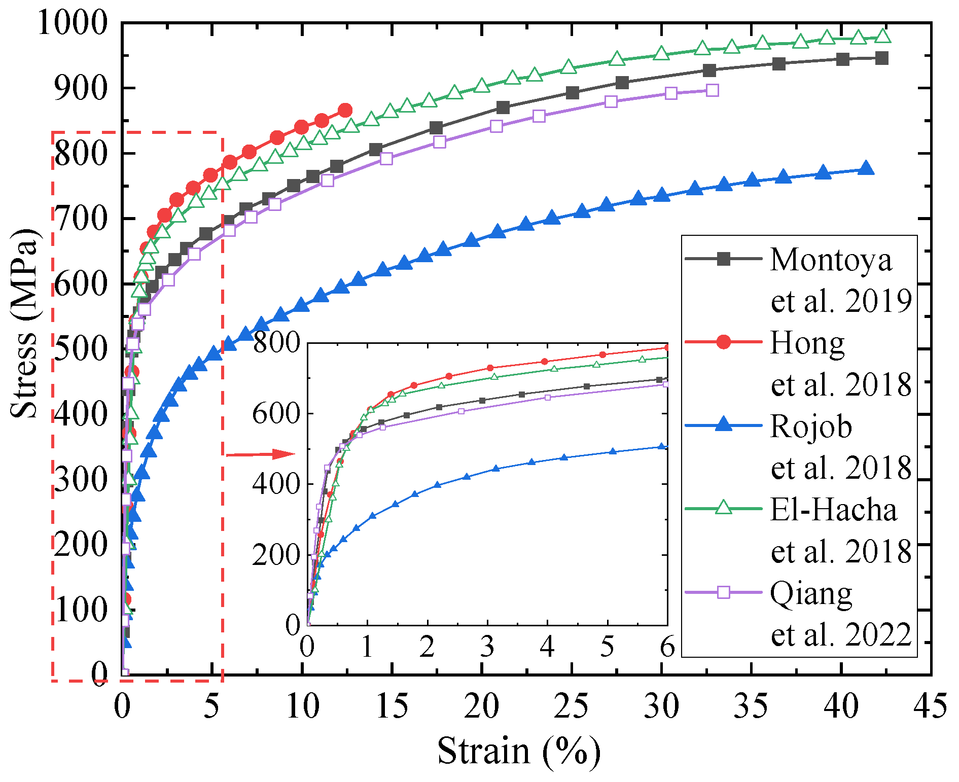
Figure 5. Stress–strain curves of Fe-SMA.
Table 4. Mechanical properties of Fe-SMA.
| Alloys | Elastic Modulus (Gpa) |
σy,0.2 | (MPa) |
Ultimate Strength (MPa) |
Ultimate Strain (%) |
References | |||||||
|---|---|---|---|---|---|---|---|---|---|---|---|---|---|
| Fe-SMA | 7200~7500 | 170 | 16.5 × 10 | −6 | 0.359 | 16~30 | 680~1000 | ||||||
| Fe-17Mn-5Si-10Cr-4Ni-1(V,C) | 194 | 476 | 950 | 45 | [15] | ||||||||
| Steel–Q235 | 7860 | 208 | 11~13 × 10 | −6 | 0.294 | 25 | 467 | ||||||
| 184 | 450 | 950 | 54 | [31] | Steel–Q355 | 206 | |||||||
| 160 | 535 | 25 | 533 | ||||||||||
| ≈1000 | 47 | [ | 67 | ] | Steel–Q690 | 218 | 7 | 990 | |||||
| 173 | 546 | 1015 | 54.9 | [83] | [76] | Concrete | 1950~2500 | 32.5 | 12 × 10 | −6 | 0.18~0.21 | — | — |
3.2. Cyclic Mechanical Properties
When reinforcing structures, the mechanical properties of Fe-SMA under cyclic load, such as pseudo-static and fatigue load, are noteworthy and crucial. In this regard, the Empa Institute has carried out some relevant studies, in which the alloy elements are Fe-17Mn-5Si-10Cr-4Ni-1(V,C). Ghafoori et al. [83][76] studied the pseudo-static performance of Fe-SMA with a 1% strain increment, and the loading curves are presented in Figure 6a. The hardening of Fe-SMA occurs under cyclic load, due to the corresponding stress in the pseudo-static process being higher than that in the static tensile process. According to the study by Koster et al. [84][77], the stress corresponding to the pseudo-static tensile strain of 9% is about 60 MPa higher than that in the static tensile test. Additionally, owing to the pseudo-elasticity of Fe-SMA, the unloading process of hysteresis curves does not follow Hooke’s law, and this discovery is of great significance for the energy dissipation capacity of Fe-SMA.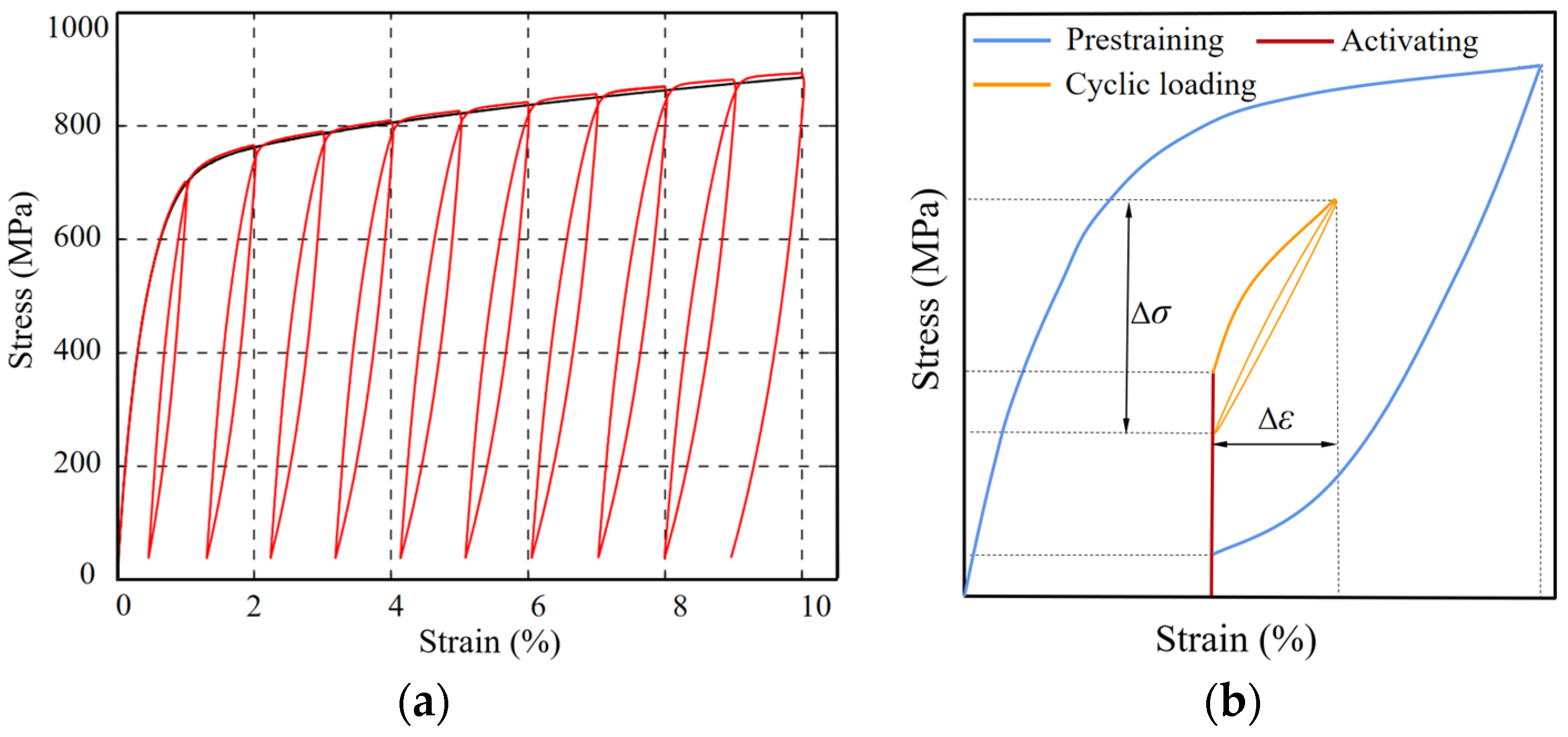
Figure 6. Loading curves of Fe-SMA: (a) under pseudo-static load, (b) under fatigue load after activation.
3.3. Stress Relaxation and Creep
Previous studies have found that stress relaxation and creep are notable characteristics of Fe-SMA. Michels et al. [88][83] obtained a recovery stress of 316 MPa of Fe-SMA, but the recovery stress decreased 19 MPa (accounting for 6% of the total recovery stress) after maintaining the displacement for 10 h. Schranz et al. [89][84] discovered that stress relaxation is slightly dependent on recovery stress, but further investigation is necessary to thoroughly understand their relationship. In the fatigue loading process, Ghafoori et al. [83][76] found that the stress relaxation mostly took place in the early stage, and the recovery stress decreased by roughly 10–20% under different strain amplitudes after 2 × 10⁶ loading cycles. Therefore, the stress loss caused by stress relaxation should be considered when using Fe-SMA to reinforce structures, and stress compensation shall be performed by secondary activation under special conditions. Except for normal room temperature, the relaxation and creep of Fe-SMA are also affected by different ambient temperatures. Weber et al. [90][85] investigated the stress relaxation and creep of Fe-SMA in the temperature range of −45 °C–50 °C, and found that both the two increased with the decrease in temperatures. Keeping the temperature at 45 °C, the alloy experienced a 0.6% creep with the constant stress of 600 MPa in 30 min, or incurred a stress relaxation of 10% when the strain remained constant. Ghafoori et al. [69] carried out a series of transient total deformation tests under high temperatures. The initial creep and failure temperatures decreased with the increase in load level, while all the initial creep temperatures were above 500 °C. This research is very significant for the potential fire hazards faced by Fe-SMA in engineering reinforcement.References
- Woo, S.K.; Nam, J.W.; Kim, J.H.J.; Han, S.H.; Byun, K.J. Suggestion of Flexural Capacity Evaluation and Prediction of Prestressed CFRP Strengthened Design. Eng. Struct. 2008, 30, 3751–3763.
- Ghafoori, E.; Motavalli, M.; Botsis, J. Fatigue Strengthening of Damaged Metallic Beams Using Prestressed Unbonded and Bonded CFRP Plates. Int. J. Fatigue 2012, 44, 303–315.
- Ghafoori, E.; Motavalli, M.; Nussbaumer, A. Design Criterion for Fatigue Strengthening of Riveted Beams in a 120-year-old Railway Metallic Bridge Using Pre-stressed CFRP Plates. Compos. Part B Eng. 2015, 68, 1–13.
- Qiang, X.H.; Bijlaard, F.S.K.; Kolstein, H.; Jiang, X. Behaviour of Beam-to-column High Strength Steel Endplate Connections Under Fire Conditions-Part 1: Experimental Study. Eng. Struct. 2014, 64, 23–38.
- Qiang, X.H.; Shu, Y.; Jiang, X. Mechanical Behaviour of High Strength Steel T-stubs at Elevated Temperatures: Experimental Study. Thin-Walled Struct. 2023, 182, 110314.
- Araujo, M.; Castro, J.M. A Critical Review of European and American Provisions for the Seismic Assessment of Existing Steel Moment-Resisting Frame Buildings. J. Earthq. Eng. 2017, 22, 1336–1364.
- Huo, T.; Tong, L.W. An Approach to Wind-induced Fatigue Analysis of Wind Turbine Tubular Towers. J. Constr. Steel Res. 2020, 166, 105917.
- Janke, L.; Czaderski, C.; Motavalli, M.; Ruth, J. Applications of Shape Memory Alloys in Civil Engineering Structures-Overview, Limits and New Idea. Mater. Struct. 2005, 38, 578–592.
- Hariri, N.G.; Almadani, I.K.; Osman, I.S. A State-of-the-Art Self-Cleaning System Using Thermomechanical Effect in Shape Memory Alloy for Smart Photovoltaic Applications. Materials 2022, 15, 5704.
- Cao, S.S.; Ozbulut, O.E. Long-stroke Shape Memory Alloy Restrainers for Seismic Protection of Bridges. Smart Mater. Struct. 2020, 29, 115005.
- Wang, B.; Zhu, S.Y. Superelastic SMA U-shaped Dampers with Self-centering Functions. Smart Mater. Struct. 2018, 27, 055003.
- Sergio, D.A.O.; Vanderson, M.D.; Marcelo, A.S.; Pedro, M.C.L.P.; Alberto, P. A Phenomenological Description of Shpae Memory Alloy Transformation Induced Plasticity. Mecc. J. Ital. Assoc. Theor. Appl. Mech. 2018, 53, 2503–2523.
- Zou, Q.; Dang, G.; Li, Y.G.; Wang, M.Z.; Xiong, J.C. Research Progress of Iron-based Shape Memory Alloys: A Review. Mater. Rep. 2019, 23, 3955–3962. (In Chinese)
- Cao, S.S.; Ozbulut, O.E.; Shi, F.; Deng, J. Experimental and Numerical Investigations on Hysteretic Response of a Multi-level SMA/lead Rubber Bearing Seismic Isolation System. Smart Mater. Struct. 2022, 31, 035024.
- Montoya-Coronado, L.A.; Ruiz-Pinilla, J.G.; Ribas, C.; Cladera, A. Experimental Study on Shear Strengthening of Shear Critical Rc Beams Using Iron-based Shape Memory Alloy Strips. Eng. Struct. 2019, 200, 109680.
- Seo, J.W.; Kim, Y.C.; Hu, J.W. Pilot Study for Investigating the Cyclic Behavior of Slit Damper Systems with Recentering Shape Memory Alloy (SMA) Bending Bars Used for Seismic Restrainers. Appl. Sci. 2015, 5, 187–208.
- Mas, B.; Biggs, D.; Vieito, I.; Shaw, J.; Vieito, I.; Martínez-Abella, F. Superelastic Shape Memory Alloy Cables for Reinforced Concrete Applications. Constr. Build. Mater. 2017, 148, 307–320.
- Tabrizikahou1, A.; Kuczma, M.; Łasecka-Plura, M.; Farsangi, E.N.; Noori, M.; Gardoni, P.; Li, S.F. Application and modelling of Shape-Memory Alloys for structural vibration control: State-of-the-art review. Constr. Build. Mater. 2022, 342, 127975.
- Deng, J.; Hu, F.; Ozbulut, O.E.; Cao, S.S. Verification of Multi-level SMA/lead Rubber Bearing Isolation System for Seismic Protection of Bridges. Soil Dyn. Earthq. Eng. 2022, 161, 107380.
- Maji, A.K.; Negret, I. Smart Prestressing with Shape-Memory Alloy. J. Eng. Mech. 1998, 124, 1121–1128.
- Czaderski, C.; Hahnebach, B.; Motavallia, M. RC Beam with Variable Stiffness and Strength. Constr. Build. Mater. 2006, 20, 824–833.
- Rogowski, J.; Kotynia, R. Comparison of Prestressing Methods with CFRP and SMA Materials in Flexurally Strengthened RC Members. Materials 2022, 15, 1231.
- Ölander, A. An Electrochemical Investigation of Solid Cadmium-Gold Alloys. J. Am. Chem. Soc. 1932, 54, 3819–3833.
- Kurdjumov, G.V.; Khandros, L.G. First Reports of The Thermoelastic Behaviour of The Martensitic Phase of Au-Cd Alloys. Dokl. Akad. Nauk. SSSR 1949, 66, 211–221.
- Chang, L.C.; Read, T.A. Behavior of The Elastic Properties of AuCd. Trans. Met. Soc. AIME 1951, 191, 47–52.
- Buehler, W.J.; Gilfrich, J.V.; Wiley, R.C. Effect of Low-Temperature Phase Changes on the Mechanical Properties of Alloys near Composition TiNi. J. Appl. Phys. 1963, 34, 1475–1477.
- Otsuka, K. Origin of Memory Effect in Cu-Al-Ni Alloy. Jpn. J. Appl. Phys. 1971, 10, 571–579.
- Sato, A.; Chishima, E.; Soma, K.; Mori, T. Shape Memory Effect in γ⇄ε Transformation in Fe-30Mn-1Si Alloy Single Crystals. Acta Metall. 1982, 30, 1177–1183.
- Sato, A.; Chishima, E.; Yamaji, Y. Orientation and Composition Dependencies of Shape Memory Effect in Fe-Mn-Si Alloys. Acta Metall. 1984, 32, 539–547.
- Mohd, J.J.; Leary, M.; Subic, A.; Gibson, M.A. A Review of Shape Memory Alloy Research, Applications and Opportunities. Mater. Des. 2014, 56, 1078–1113.
- Rosa, D.I.H.; Hartloper, A.; Sousa, A.D.C.E.; Lignos, D.G.; Motavalli, M.; Ghafoori, E. Experimental Behavior of Iron-based Shape Memory Alloys under Cyclic Loading Histories. Constr. Build. Mater. 2021, 272, 121712.
- Cladera, A.; Weber, B.; Leinenbach, C. Iron-based Shape Memory Alloys for Civil Engineering Structures: An Overview. Constr. Build. Mater. 2014, 63, 281–293.
- Czaderski, C.; Shahverdi, M.; Michels, J. Iron Based Shape Memory Alloys as Shear Reinforcement for Bridge Girders. Constr. Build. Mater. 2021, 274, 121793.
- Yeon, Y.M.; Hong, K.N.; Ji, S.W. Flexural Behavior of Self-Prestressed RC Slabs with Fe-Based Shape Memory Alloy Rebar. Appl. Sci. 2022, 12, 1640.
- Choi, E.; Ostadrahimi, A.; Kim, W.J.; Seo, J. Prestressing Effect of Embedded Fe-Based SMA Wire on the Flexural Behavior of Mortar Beams. Eng. Struct. 2021, 227, 111472.
- Yamauchi, K.; Ohkata, I.; Tsuchiya, K.; Miyazaki, S. Shape Memory and Superelastic Alloys: Technologies and Applications; Woodhead Publishing Limited: Cambridge, UK, 2011; Chapter 12; pp. 141–159.
- Wayman, C.M. On Memory Effects Related to Martensitic Transformations and Observations in β-Brass and Fe3Pt. Scr. Metall. 1971, 5, 489–492.
- Sohmura, T.; Oshima, R.; Fujita, F.E. Thermoelastic FCC-FCT Martensitic Transformation in Fe-Pd Alloy. Scr. Metall. 1980, 14, 855–856.
- Xiao, F.; Fukuda, T.; Kakeshita, T.; Takahashi, K. Concentration Dependence of FCC to FCT Martensitic Transformation in Fe-Pd Alloys. J. Alloys Compd. 2013, 577, S323–S326.
- Maki, T.; Kobayashi, K.; Minato, M.; Tamura, I. Thermoelastic Martensite in an Ausaged Fe-Ni-Ti-Co Alloy. Scr. Metall. 1984, 18, 1105–1109.
- Cesari, E.; Chernenko, V.A.; Kokorin, V.V.; Pons, J.; Seguí, C. Physical Properties of Fe-Co-Ni-Ti Alloy in the Vicinity of Martensitic Transformation. Scr. Mater. 1999, 40, 341–345.
- Guimarães, J.R.C.; Rios, P.R. The Mechanical-induced Martensite Transformation in Fe-Ni-C Alloys. Acta Mater. 2015, 84, 436–442.
- Xu, Z.Y.; Jiang, B.H. Shape Memory Materials; Shanhai Jiaotong University Press: Shanghai, China, 2000; pp. 204–220. (In Chinese)
- Li, K.; Dong, Z.Z.; Liu, Y.C. A Newly Developed Fe-based Shape Memory Alloy Suitable for Smart Civil Engineering. Smart Mater. Struct. 2013, 22, 045002.
- Sawaguchi, T.; Maruyama, T.; Otsuka, H.; Kushibe, A.; Inoue, Y.; Tsuzaki, K. Design Concept and Applications of Fe-Mn-Si-Based Alloys-from Shape-Memory to Seismic Response Control. Mater. Trans. 2016, 57, 283–293.
- Soroushian, P.; Ostowari, K.; Nossoni, A.; Chowdhury, H. Repair and Strengthening of Concrete Structures through Application of Corrective Posttensioning Forces with Shape Memory Alloys. Transp. Res. Board 2001, 1770, 20–26.
- Sato, A.; Kubo, H.; Maruyama, T. Mechanical Properties of Fe-Mn-Si Based SMA and The Application. Mater. Trans. 2006, 47, 571–579.
- Otsuka, H.; Yamada, H.; Maruyama, T.; Tanahashi, H.; Matsuda, S.; Murakami, M. Effects of Alloying Additions on Fe-Mn-Si Shape Memory Alloys. Trans. Iron Steel Inst. Jpn. 1990, 30, 674–679.
- Koyama, M.; Sawaguchi, T.; Tsuzaki, K. Si Content Dependence on Shape Memory and Tensile Properties in Fe–Mn–Si–C Alloys. Mater. Sci. Eng. A 2011, 528, 2882–2888.
- Sawaguchi, T.; Nikulin, I.; Ogawa, K.; Sekido, K.; Takamori, S.; Maruyama, T.; Chiba, Y.; Kushibe, A.; Inoue, Y.; Tsuzaki, K. Designing Fe–Mn–Si Alloys with Improved Low-cycle Fatigue Lives. Scr. Mater. 2015, 99, 49–52.
- Lin, H.C.; Lin, K.M.; Lin, C.S.; Chen, F.H. The Corrosion Behavior of Fe-Based Shape Memory Alloys. Corros. Sci. 2002, 14, 439–442.
- Maji, B.C.; Das, C.M.; Krishnan, M.; Ray, R.K. The Corrosion Behaviour of Fe-15Mn-7Si-9Cr-5Ni Shape Memory Alloy. Corros. Sci. 2006, 48, 937–949.
- Wan, J.F.; Chen, S.P.; Hsu, T.Y.; Huang, Y.N. Modulus Softening During The γ→ɛ Martensitic Transformation in Fe-25Mn-6Si-5Cr-0.14N Alloys. Mater. Sci. Eng. A 2006, 438, 887–890.
- Wang, D.F.; Chen, Y.R.; Gong, F.Y.; Liu, D.Z.; Liu, W.X. The Effect of Thermomechanical Training on the Microstructures of Fe-Mn-Si Shape Memory Alloy. J. Phys. IV (Proc.) 1995, 5, 527–530.
- Kajiwara, S.; Liu, D.Z.; Kikuchi, T.; Shinya, N. Remarkable Improvement of Shape Memory Effect in Fe-Mn-Si Based Shape Memory Alloys by Producing NbC Precipitate. Scr. Mater. 2001, 44, 2809–2814.
- Farjami, S.; Hiraga, K.; Kubo, H. Shape Memory Effect and Crystallographic Investigation in VN Containing Fe-Mn-Si-Cr Alloys. Mater. Trans. 2004, 45, 930–935.
- Dong, Z.Z.; Klotz, U.E.; Leinenbach, C.; Bergamini, A.; Czaderski, C.; Motavalli, M. A Novel Fe-Mn-Si Shape Memory Alloy with Improved Shape Recovery Properties by VC Precipitation. Adv. Eng. Mater. 2009, 11, 40–44.
- Murakami, M.; Otsuka, H.; Suzuki, H.; Matsuda, S. Complete Shape Memory Effect in Polycrystalline Fe-Mn-Si Alloys. In Proceedings of the International Conference on Martensitic Transformations, Nara, Japan, 26–30 August 1986; pp. 985–990.
- Dong, Z.Z.; Kajiwara, S.; Kikuchi, T.; Sawaguchi, T. Effect of Pre-deformation at Room Temperature on Shape Memory Properties of Stainless Type Fe–15Mn–5Si–9Cr–5Ni–(0.5–1.5)NbC Alloys. Acta Mater. 2005, 53, 4009–4018.
- Dong, Z.Z.; Sawaguchi, T.; Kajiwara, S.; Kikuchi, T.; Kim, S.H.; Lee, G.C. Microstructure Change and Shape Memory Characteristics in Welded Fe-28Mn-6Si-5Cr-0.53Nb-0.06C Alloy. Mater. Sci. Eng. A 2006, 438, 800–803.
- Zhang, W.; Wen, Y.H.; Li, N.; Xie, W.L.; Wang, S.H. Directional Precipitation of Carbides Induced by c/e Interfaces in an FeMnSiCrNiC Alloy Aged after Deformation at Different Temperature. Mater. Sci. Eng. A 2007, 459, 324–329.
- Otsuka, K.; Wayman, C.M. Shape Memory Materials; Cambridge University Press: Cambridge, UK, 1998.
- Qiang, X.H.; Chen, L.L.; Jiang, X. Achievements and Perspectives on Fe-Based Shape Memory Alloys for Rehabilitation of Reinforced Concrete Bridges: An Overview. Materials 2021, 22, 8089.
- Lei, Z. Fe-based Shape-memory Alloy and its Applications. Dev. Appl. Mater. 2000, 15, 40–45. (In Chinese)
- Jin, X.; Jin, M.; Geng, Y. Recent Development of Martensitic Transformation in Ferrous Shape Memory Alloys. Mater. China 2011, 56, 32–41. (In Chinese)
- Lee, W.J.; Weber, B.; Feltrin, G.; Czaderski, C.; Motavalli, M.; Leinenbach, C. Phase Transformation Behavior under Uniaxial Deformation of An Fe-Mn-Si-Cr-Ni-VC Shape Memory Alloy. Mater. Sci. Eng. A 2013, 581, 1–7.
- Shahverdi, M.; Michels, J.; Czaderski, C.; Motavalli, M. Iron-based Shape Memory Alloy Strips for Strengthening RC Members: Material Behavior and Characterization. Constr. Build. Mater. 2018, 173, 586–599.
- Sun, L.; Hhang, W.M. Nature of The Multistage Transformation in Shape Memory Alloys Upon Heating. Met. Sci. Heat Treat. 2009, 51, 573–578.
- Ghafoori, E.; Neuenschwander, M.; Shahverdi, M.; Czaderski, C.; Fontana, M. Elevated Temperature Behavior of an Iron-based Shape Memory Alloy Used for Prestressed Strengthening of Civil Structures. Constr. Build. Mater. 2019, 211, 437–452.
- Maruyama, T.; Kurita, T.; Kozaki, S.; Andou, K.; Farjami, S.; Kubo, H. Innovation in Producing Crane Rail Fish Plate Using Fe-Mn-Si-Cr Based Shape Memory Alloy. Mater. Sci. Technol. 2008, 24, 908–912.
- Shahverdi, M.; Czaderski, C.; Annen, P.; Motavalli, M. Strengthening of RC Beams by Iron-based Shape Memory Alloy Bars Embedded in a Shotcrete Layer. Eng. Struct. 2016, 117, 263–273.
- Czaderski, C.; Shahverdi, M.; Brönnimann, R.; Leinenbach, C.; Motavalli, M. Feasibility of Iron-Based Shape Memory Alloy Strips for Prestressed Strengthening of Concrete Structures. Constr. Build. Mater. 2014, 56, 94–105.
- Hosseini, A.; Ghafoori, E.; Al-Mahaidi, R.; Zhao, X.L.; Motavalli, M. Strengthening of A 19th-century Roadway Metallic Bridge Using Nonprestressed Bonded and Prestressed Unbonded CFRP Plates. Constr. Build. Mater. 2019, 209, 240–259.
- Ghafoori, E.; Hosseini, A.; Al-Mahaidi, R.; Zhao, X.L.; Motavalli, M. Prestressed CFRP-Strengthening and Long-Term Wireless Monitoring of an Old Roadway Metallic Bridge. Eng. Struct. 2018, 176, 585–605.
- Hosseini, E.; Ghafoori, E.; Leinenbach, C.; Motavalli, M.; Holdsworth, S. Stress Recovery and Cyclic Behaviour of An Fe-Mn-Si Shape Memory Alloy after Multiple Thermal Activation. Smart Mater. Struct. 2018, 27, 025009.
- Ghafoori, E.; Hosseini, E.; Leinenbach, C. Fatigue Behavior of a Fe-Mn-Si Shape Memory Alloy Used for Prestressed Strengthening. Mater. Des. 2017, 133, 349–362.
- Koster, M.; Lee, W.J.; Schwarzenberger, M.; Leinenbach, C. Cyclic Deformation and Structural Fatigue Behavior of an FE-Mn-Si Shape Memory Alloy. Mater. Sci. Eng. A 2015, 637, 29–39.
- Hong, K.; Lee, S.; Yeon, Y.M.; Jung, K. Flexural Response of Reinforced Concrete Beams Strengthened with Near-Surface-Mounted Fe-Based Shape-Memory Alloy Strips. Int. J. Concr. Struct. Mater. 2018, 12, 45.
- Qiang, X.H.; Wu, Y.P.; Jiang, X. Experimental Investigation on Mechanical Properties and Activation-recovery Performance of Fe-based Shape memory alloys. J. Tongji Univ. (Nat. Sci.), 2022; in press.
- Hong, K.N.; Yeon, Y.M.; Shim, W.B.; Kim, D.H. Recovery Behavior of Fe-Based Shape Memory Alloys under Different Restraints. Appl. Sci. 2020, 10, 3441.
- Inoue, Y.; Kushibe, A.; Umemura, K.; Mizushima, Y.; Sawaguchi, T.; Nakamura, T.; Otsuka, H.; Chiba, Y. Fatigue-resistant Fe-Mn-Si-based Alloy Seismic Dampers to Counteract Long-period Ground Motion. Jpn. Archit. Rev. 2020, 4, 76–87.
- Fang, C.; Wang, W.; Ji, Y.; Yam, M.C. Superior Low-cycle Fatigue Performance of Iron-based SMA for Seismic Damping Application. J. Constr. Steel Res. 2021, 184, 106817.
- El-Hacha, R.; Michels, J.; Shahverdi, M.; Czaderski, C. Mechanical Performance of Iron-Based Shape-Memory Alloy Ribbed Bars for Concrete Prestressing. ACI Mater. J. 2018, 115, 877–886.
- Schranz, B.; Czaderski, C.; Shahverdi, M.; Michels, J.; Motavalli, M. Ribbed Iron-based Shape Memory Alloy Bars for Pre-stressed Strengthening Applications. In Proceedings of the International Association for Bridge and Structural Engineering Symposium, Guimaraes, Portugal, 27–29 March 2019.
- Leinenbach, C.; Lee, W.J.; Lis, A.; Arabi-Hashemi, A.; Cayron, C.; Weber, B. Creep and Stress Relaxation of a FeMnSi-based Shape Memory Alloy at Low Temperatures. Mater. Sci. Eng. A 2016, 677, 106–115.
More
