Your browser does not fully support modern features. Please upgrade for a smoother experience.
Please note this is a comparison between Version 2 by Camila Xu and Version 1 by Lingxue Kong.
Lyotropic liquid crystals (LLCs) are promising templates for active layer materials due to their inherently uniform and controllable pore size, ranging from 0.2 to 5 nm. Membranes formed by LLC template materials possess low surface roughness and high hydrophilicity, which result in higher membrane-fouling resistance. Moreover, mesophases such as hexagonal and lamellar are reorientable, enabling water channels to align perpendicularly to the membrane surface and increasing water permeance.
- lyotropic liquid crystal
- nanofiltration
- interfacial structure
1. Introduction
The reduction in the supply of freshwater has prompted governments and scientists to develop water purification technologies [1]. As seawater makes up 96.5% of the total global water supply, seawater desalination is the most promising way to increase potable water supplies [2]. However, desalination consumes 6–7 times more energy than conventional water treatment methods to purify an equivalent amount of water [3]. In a common desalination plant, the membrane unit accounts for 85% of the overall energy consumption [4]. Therefore, improving membrane efficiency is crucial in reducing overall desalination energy consumption and further popularizing desalination techniques.
Thin-film composite (TFC) membranes, consisting of an active separation layer, porous support, and polyester non-woven backing layer, are considered a state-of-the-art design for seawater desalination membranes [5,6,7][5][6][7]. The active layer of commercial TFC membranes is typically a nonporous aromatic cross-linked polyamide (PA) [8]. Although this type of TFC is widely used, it is limited by its low permeability (<1 Lm−2 h−1 bar−1 μm) [9[9][10],10], non-uniform pore size [11], and low fouling resistance [7]. Lyotropic liquid crystals (LLCs) are promising templates for active layer materials due to their inherently uniform and controllable pore size, ranging from 0.2 to 5 nm [9,12,13,14,15,16][9][12][13][14][15][16]. Membranes formed by LLC template materials possess low surface roughness and high hydrophilicity, which result in higher membrane-fouling resistance [17]. Moreover, mesophases such as hexagonal and lamellar are reorientable, enabling water channels to align perpendicularly to the membrane surface and increasing water permeance.
Current studies on fabricating TFC membranes based on the LLC template active layer all directly form the LLC mesophase on substrates since this method guarantees interface [10]. However, research has shown that the surface properties of the substrate, including hydrophilicity and heterogeneity, could significantly affect the types and shapes of surfactant mesophases [18]. As LLCs are also formed by surfactants, it is reasonable to wonder about the accurate structures at the LLC/substrate interface. However, this essential part has been overlooked.
Studies on the conventional PA-based active layer show that the middle porous substrate of TFC not only regulates the water transport path but also interferes with the structure formation of the active layer [19]. For example, the funnel effect leads to a longer transport pathway of water on the substrate with low porosity [20,21][20][21]. Regarding structure formation interferences, the nanovoids formation on the PA surface has been effectively controlled by the surface pore size of the substrates, which can be explained by a volcano-like model [22] and the confinement effect [23,24][23][24]. In addition, the infusion depth of the PA layer in the substrate was found to be altered by both surface pore size and hydrophilicity [25,26,27][25][26][27]. Commercial polymer substrates are usually limited by their material nature, which is hydrophobic, has less porosity, and cannot enable the top layer to exert functions effectively.
Fortunately, the limitations of polymer substrates can be remedied by emerging surface modification and by introducing an interlayer between the substrate and top layer [28,29][28][29]. Surface modification methods, including surface deposition and surface grafting, usually focus on tackling the polymer surface hydrophobicity [29], while introducing an interlayer could bring additional benefits, such as adjusting the overall water channel [30], restricting the active layer infusion, and facilitating the formation of a uniform and defect-free top layer [31].
In addition to optimizing the surface properties of the substrates, accurately detecting the LLC/substrate interfacial structures is also of great importance for optimizing the interface. Microscopic methods such as scanning electron microscopy and transmission electron microscopy are usually destructive to the membranes and limited to probing small sample areas. X-ray and neutron techniques are more promising in non-destructively observing the buried LLC/substrate interfacial structures. The grazing incidence mode scattering technique is the most direct tool to identify the LLC phase structure at the interface by choosing a suitable beam incident angle [32], while neutron enables localization of the monomer molecules at the interface by contrast matching the deuterated amphiphile molecules and the mixtures of deuterated and hydrogen solvents [33].
2. Fabrication of LLC Active Layer with Suitable Structure Retention
The structure of TFC membranes based on the LLC template active layer typically consists of a top LLC template layer and a porous substrate. The porous substrates are typically commercially purchased microfiltration or ultrafiltration membranes or self-prepared (phase inverse method) porous membranes. This section presents the main efforts made in the fabrication of the LLC active layer on porous membranes, focusing on LLC phase behavior, structure retention, and a comparison of the resulting membranes structures and performances.2.1. LLC Precursor on Porous Substrates
2.1.1. LLC Phases
LLCs are assemblies composed of amphiphilic molecules that contain a hydrophilic headgroup and a hydrophobic organic tail in the presence of a polar solvent, usually water. The amphiphilic nature of these molecules drives them to phase separation upon the addition of polar solvent, resulting in the formation of ordered hydrophobic and hydrophilic domains with water–oil interfaces determined by hydrophilic headgroups. The most common phases of LLC are lamellar (L), hexagonal (H), bi-continuous cubic (Q), and discontinuous cubic (I). Among these, the normal hexagonal phase (HI), inverted hexagonal phase (HII), and normal bi-continuous cubic (QI) are most commonly used as the template for fabricating top layers [10,16[10][16][34][35],34,35], as shown in Figure 1. Saadat and his coworkers have summarized the reactive and non-reactive surfactants that have been used to form these mesophases [17]. Compared to other mesophases, the hexagonal mesophase template materials are more promising for fabricating top layers with pores parallel to the macroscopic transport direction, i.e., vertical to the membrane surface. Such a tubular HLLC domain was verified to be reoriented using several up-to-date techniques, including magnetic field [14,36[14][36][37][38][39],37,38,39], electrical fields [40[40][41][42],41,42], shear force [10[10][12][43][44][45][46],12,43,44,45,46], and confinement methods [13,47][13][47].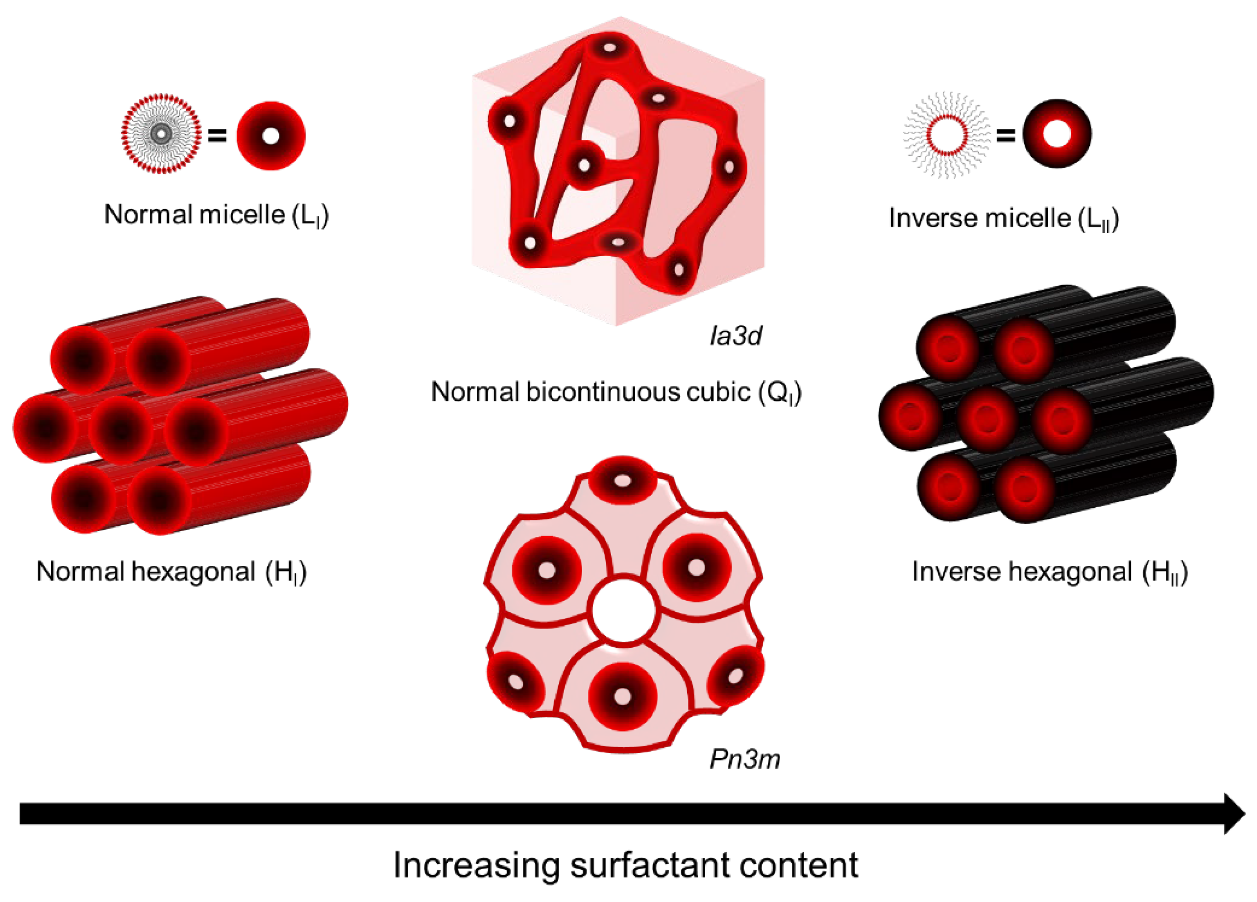
Figure 1.
LLC phases used as template for fabricating top layer.
2.1.2. LLC Phase Behavior
A lipid monolayer possessing a spontaneous curvature can be bent with a concave surface to form cylinders, which is the basis of the LLC phase transition. The free energy of bending a thin surfactant layer can be calculated by [48]:where lower free energy of bending a thin layer corresponds to a higher spontaneous
. However, this theory cannot explain the energy changes during the phase transition between the lamellar and hexagonal phases since the
is zero for the lamellar phase. In this case, the hydrocarbon packing energy theory was introduced [49][50][51]. The lamellar phase possesses a low hydrocarbon packing energy and a high bending energy, which means that the lower hydrocarbon packing energy drives the phase transition from the lamellar to the hexagonal phase when increasing the
of the flat layer. Therefore, the competition between the curvature on the interface of the mesophases and hydrocarbon packing mainly determines the structure of the LLC phase [48]. The temperature [52], pressure [53][54], pH value [55], and introducing agents such as inorganic salts [56][57] and alkanes [58] have been found to modulate the packing and bending energies of the LLC system. For instance, the decrease in temperature was found to increase the radius of the water core of the H
, which increases the hydrocarbon packing energy and forms a cylinder with a lower spontaneous curvature of the system. In this case, the introduction of a long-chain alkane can decrease the packing energy and increase the spontaneous curvature of the system, which stabilizes the LLC phase [48]. Efforts to control the LLC phase structure, LLC unit cell size, and diameter of the water phase in LLC have been motivated by many applications, including drug release and protein loading [59][60][61].
2.1.3. Polar Solvent
Water is the most typical polar solvent used in LLC mesophase. However, the inevitable evaporation of water limits the retention of LLC phase structures. This problem can be addressed by replacing the water with other polar organic solvents with lower volatility, such as glycerol, ionic liquids, ethylene glycol, N-methylsydone, formamide and its derivatives, and propylene carbonate [62,63,64][62][63][64]. These solvents have been studied to form LLC phases with alternative surfactants.2.2. Ultrathin LLC Film Formation on Porous Substrates
2.2.1. LLC Templating
LLC mesophases suffer from poor mechanical and thermal properties, which limit their applications. Therefore, they are often used as templates to be polymerized into polyLLCs to overcome these limitations. Two common routes can be implemented to achieve robust polyLLCs: synergistic and transcriptive templating. The synergistic method is more direct since it cures the polymerizable surfactant directly, while the latter one cures the introduced monomers or crosslinkers in the confined area in the LLC template. Generally, self-assembly is a process by which molecules move to minimize their free energy. When transferring the LLC parent template to the polymer, the entropy of the system decreases, while the enthalpy of the isolated system commonly undergoes almost no change during the polymerization. Therefore, an increase in the free energy of the system will inevitably occur, leading to the collapse of the template structure. Two strategies can be used to avoid the loss of the parent structure [65]:-
Establishing strong enough thermodynamic interactions between the surfactant template and polymer;
-
Increasing the system viscosity and chain entanglement by forming covalent and limiting species diffusion.
2.2.2. Fabrication Process
Roll-casting, hot or cold pressing, and spin-coating were used to fabricate LLC-based TFC membranes, as shown in Figure 2A. To fabricate a robust LLC-based TFC membrane, the inverse hexagonal (HII) phase was first roll-cast onto the commercial microporous polysulfone (Psf) support. Although this fabrication method is facile, the inevitable evaporation of water causes limited retention of HII phase structures.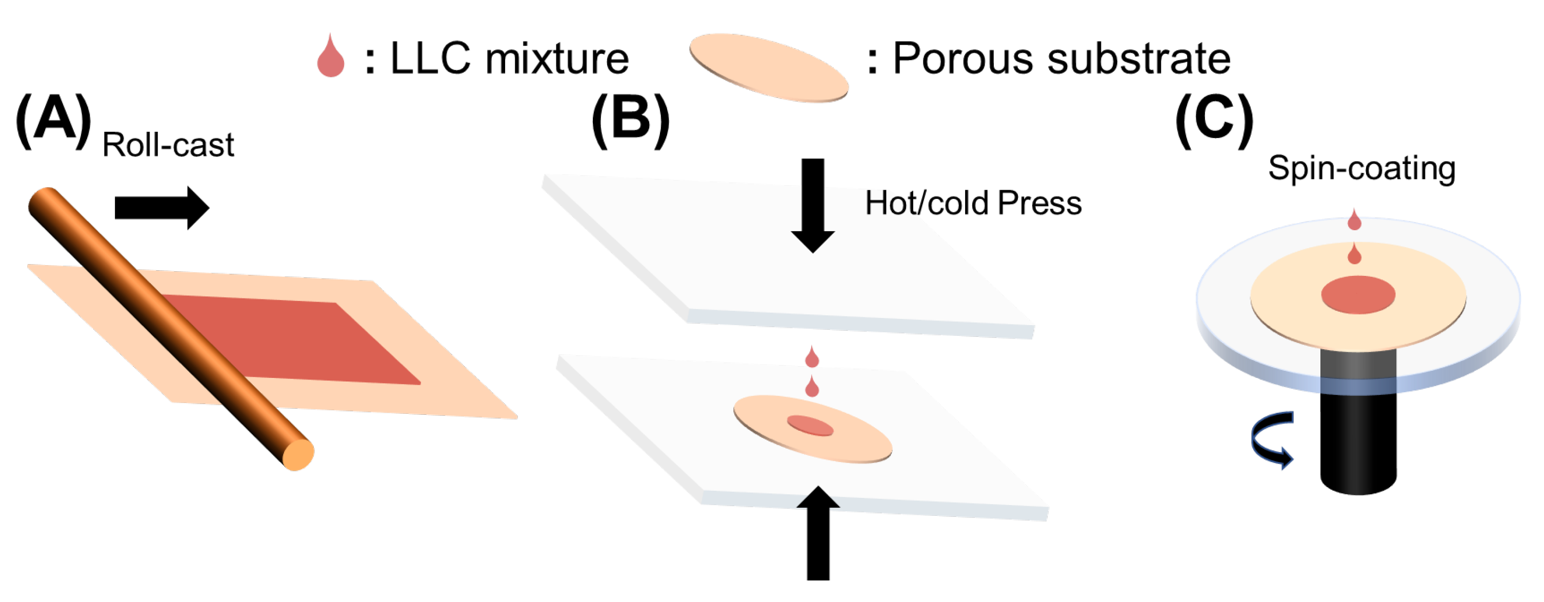
Figure 2.
Methods to fabricate LLC-based TFC membranes. (
A
) Roll-casting; (
B
) hot or cold pressing; (
C
) Spin-coating.
2.3. Performance of TFC Membranes with LLC as the Active Layer
Many LLC template membranes currently outperform the previous ones limited by trade-off, and their performances are comparable to commercial membranes (Table 1). Studies have mainly focused on building the outperformed TFCs with LLC active layers using hexagonal columnar LLC and cubic LLC. Gin and his coworkers reported a TFC with an inverted hexagonal (HII) phase as the active layer and polysulfone (Psf) UF as the substrate [34]. This HII active layer with 0.6 μm possesses a molecular separation pore size of about 1.2 nm. However, the isotropic cylindrical nanochannels without alignment presented a very low pure water flux of 0.053 Lm−2 h−1 bar−1 μm. Osuji et al. [10] reported a TFC membrane with a parallel aligned hexagonal (HI) phase active layer. In this study, a spin-coated ultrathin (200 nm) active layer provided a relatively high water flux of 2 Lm−2 h−1 bar−1 μm. The molecular weight cutoff (MWCO) of this TFC membrane is 300 Da for charged organic solutes and 600 Da for neutral organic solutes (1.2 nm PEG). The salt (MgCl2 and CaCl2) rejection of this membranes is more than 80%.Table 1.
Summary of the reported results for TFC membranes based on LLC template active layer.
| Ref. | LLC Phase | Porous Substrate | Fabrication Process | Solvent | Reactive Temp (°C) | Pore Size in Diameter (nm) | Thickness | Pure Water Flux | Rejection (%) |
|---|---|---|---|---|---|---|---|---|---|
| [34] | HII | PSf MF | Roll-casting | H2O | RT | 1.2 | 0.6 μm | 0.053 Lm−2 h−1 bar−1 μm | Na-TSO (60) Na-NpSO (73) Na-AnSO (89) Na-PySO (94) PEG600 (25.7) PEG5000 (96.1) PEG20000 (99.6) |
| [16] | QI | PE MF | Hot-pressing | H2O | 65 | 0.75 | 40 μm | 0.086 Lm−2 h−1 bar−1 μm | Ethidium Red (99.9) PEG-600 (99.9) Sucrose (99.9) Glucose (96) Glycerol (53) EG (38) NaCl (95) MgCl2 (99.3) CaCl2 (99.3) |
| [35] | QI | PE MF | Hot-pressing | H2O | 60 | 0.86 | 40 μm | 0.054 Lm−2 h−1 bar−1 μm | NaCl (94) KCl (92) MgCl2 (95) CaCl2 (96.9) Sucrose (97.9) Glucose (95) Glycerol (45) Ethylene glycol (38) |
| [9] | QI | PE MF | Hot-pressing | H2O | 65 | 0.75 | 40 μm | Using Ref. [16]’s LLC membrane. Water filtration performances in between that of commercial RO membranes and NF membranes | |
| [63] | QI | PES UF | Rod-coating | Glycerol | 70 | 0.96 | 3 μm | 0.054 Lm−2 h−1 bar−1 μm | Sucrose (97) Glucose (87) Glycerol (45) EG (24) NaCl (98) MgCl2(99) |
| [74] | QI | PES UF | Rod-coating | Glycerol | 70 | ≈1 | 3 μm | Using Ref. [63]’s LLC membrane. Anion exchange in the pores can adjust the flux with little change in rejection performance | |
| [75] | QI | PES UF | Rod-coating | Glycerol | 70 | ≈1 | 3 μm | Using Ref. [63]’s LLC membrane. TFC QI possesses a similar performance as commercial RO and NF membranes in treating hydraulic fracturing flowback water. Controllable DOC recovery can be adjusted by pH | |
| [76] | QI | PES UF | Rod-coating | Glycerol | 70 | ≈1 | 3 μm | Using Ref. [63]’s LLC membrane. The 66 h cross-flow filtration of hydraulic fracturing produced water was conducted. Better performance than NF90 in portion of organic compounds, water flux, and fouling resistance | |
| [68] | HII Lα |
PE MF (recovered) |
Hot-pressing | H2O | RT (UV-curing) + 70 (thermal-curing) |
4 nm (HII) 3 nm (Lα) |
10 μm | These LLC membranes possess better permeability and antifouling performances than commercially UF membranes. BSA rejection higher than 95% | |
| [12] | HI | PAN UF | Pressing | H2O | RT | 1–2 nm | 3–30 μm | 10 Lm−2 h−1 bar−1 μm | Methylene blue (90) Crystal violet (90) Alcian blue (90) Charged solutes (~350 Da) Neutral solutes (~4 kDa) |
| [10] | HI | PAN UF and PVDF UF | Spin-coating | Glycerol | RT | ~1 nm | ~200 nm | 2 Lm−2 h−1 bar−1 μm | PEG600(>94) Methyl orange (91) Methylene blue (95) CaCl2 and MgCl2 (>80) LiCl, NaCl, and KCl (>40) |
| [72] | HI | PVDF UF | Spin-coating | Glycerol | RT | 0.6–1.5 nm | 170–200 nm | 10–30 Lm−2 h−1 bar in water 2–8 Lm−2 h−1 bar−1 μm in methanol |
4 HI membranes possess various performances. Only list the maximum performances here. PEG 600 (100%) Acid Fuchsin 585 Da (> 95%) Methyl Orange 327 Da (100%) |
References
- Yang, Z.; Zhou, Y.; Feng, Z.; Rui, X.; Zhang, T.; Zhang, Z. A Review on Reverse Osmosis and Nanofiltration Membranes for Water Purification. Polymers 2019, 11, 1252.
- Wang, G.; Garvey, C.J.; Zhao, H.; Huang, K.; Kong, L. Toward the fabrication of advanced nanofiltration membranes by controlling morphologies and mesochannel orientations of hexagonal lyotropic liquid crystals. Membranes 2017, 7, 37.
- Voutchkov, N. Energy use for membrane seawater desalination—Current status and trends. Desalination 2018, 431, 2–14.
- Lim, Y.J.; Goh, K.; Kurihara, M.; Wang, R. Seawater desalination by reverse osmosis: Current development and future challenges in membrane fabrication—A review. J. Membr. Sci. 2021, 629, 119292.
- Gin, D.L.; Bara, J.E.; Noble, R.D.; Elliott, B.J. Polymerized lyotropic liquid crystal assemblies for membrane applications. Macromol. Rapid Commun. 2008, 29, 367–389.
- Ahmad, N.A.; Goh, P.S.; Abdul Karim, Z.; Ismail, A.F. Thin film composite membrane for oily waste water treatment: Recent advances and challenges. Membranes 2018, 8, 86.
- Werber, J.R.; Osuji, C.O.; Elimelech, M. Materials for next-generation desalination and water purification membranes. Nat. Rev. Mater. 2016, 1, 16018.
- Karki, S.; Ingole, P.G. Development of polymer-based new high performance thin-film nanocomposite nanofiltration membranes by vapor phase interfacial polymerization for the removal of heavy metal ions. Chem. Eng. J. 2022, 446, 137303.
- Hatakeyama, E.S.; Gabriel, C.J.; Wiesenauer, B.R.; Lohr, J.L.; Zhou, M.; Noble, R.D.; Gin, D.L. Water filtration performance of a lyotropic liquid crystal polymer membrane with uniform, sub-1-nm pores. J. Membr. Sci. 2011, 366, 62–72.
- Zhang, Y.; Dong, R.; Gabinet, U.R.; Poling-Skutvik, R.; Kim, N.K.; Lee, C.; Imran, O.Q.; Feng, X.; Osuji, C.O. Rapid Fabrication by Lyotropic Self-Assembly of Thin Nanofiltration Membranes with Uniform 1 Nanometer Pores. ACS Nano 2021, 15, 8192–8203.
- Liang, Y.; Zhu, Y.; Liu, C.; Lee, K.-R.; Hung, W.-S.; Wang, Z.; Li, Y.; Elimelech, M.; Jin, J.; Lin, S. Polyamide nanofiltration membrane with highly uniform sub-nanometre pores for sub-1 Å precision separation. Nat. Commun. 2020, 11, 2015.
- Feng, X.; Imran, Q.; Zhang, Y.; Sixdenier, L.; Lu, X.; Kaufman, G.; Gabinet, U.; Kawabata, K.; Elimelech, M.; Osuji, C.O. Precise nanofiltration in a fouling-resistant self-assembled membrane with water-continuous transport pathways. Sci. Adv. 2019, 5, eaav9308.
- Feng, X.; Kawabata, K.; Kaufman, G.; Elimelech, M.; Osuji, C.O. Highly selective vertically aligned nanopores in sustainably derived polymer membranes by molecular templating. ACS Nano 2017, 11, 3911–3921.
- Feng, X.; Tousley, M.E.; Cowan, M.G.; Wiesenauer, B.R.; Osuji, C.O. Scalable Fabrication of Polymer Membranes with Vertically Aligned 1 nm Pores by Magnetic Field Directed Self-Assembly. ACS Nano 2014, 8, 11977–11986.
- Marets, N.; Kuo, D.; Torrey, J.R.; Sakamoto, T.; Kato, T. Highly Efficient Virus Rejection with Self-Organized Membranes Based on a Crosslinked Bicontinuous Cubic Liquid Crystal. Adv. Healthc. Mater. 2017, 6, 1700252.
- Zhou, M.; Nemade, P.R.; Lu, X.; Zeng, X.; Hatakeyama, E.S.; Noble, R.D.; Gin, D.L. New type of membrane material for water desalination based on a cross-linked bicontinuous cubic lyotropic liquid crystal assembly. J. Am. Chem. Soc. 2007, 129, 9574–9575.
- Saadat, Y.; Imran, O.Q.; Osuji, C.O.; Foudazi, R. Lyotropic liquid crystals as templates for advanced materials. J. Mater. Chem. A 2021, 9, 21607–21658.
- Striolo, A.; Grady, B.P. Surfactant assemblies on selected nanostructured surfaces: Evidence, driving forces, and applications. Langmuir 2017, 33, 8099–8113.
- Peng, L.E.; Yang, Z.; Long, L.; Zhou, S.; Guo, H.; Tang, C.Y. A critical review on porous substrates of TFC polyamide membranes: Mechanisms, membrane performances, and future perspectives. J. Membr. Sci. 2022, 641, 119871.
- Karan, S.; Jiang, Z.; Livingston, A.G. Sub–10 nm polyamide nanofilms with ultrafast solvent transport for molecular separation. Science 2015, 348, 1347–1351.
- Li, X.; Li, Q.; Fang, W.; Wang, R.; Krantz, W.B. Effects of the support on the characteristics and permselectivity of thin film composite membranes. J. Membr. Sci. 2019, 580, 12–23.
- Ghosh, A.K.; Hoek, E.M. Impacts of support membrane structure and chemistry on polyamide–polysulfone interfacial composite membranes. J. Membr. Sci. 2009, 336, 140–148.
- Peng, L.E.; Yao, Z.; Yang, Z.; Guo, H.; Tang, C.Y. Dissecting the role of substrate on the morphology and separation properties of thin film composite polyamide membranes: Seeing is believing. Environ. Sci. Technol. 2020, 54, 6978–6986.
- Song, X.; Gan, B.; Yang, Z.; Tang, C.Y.; Gao, C. Confined nanobubbles shape the surface roughness structures of thin film composite polyamide desalination membranes. J. Membr. Sci. 2019, 582, 342–349.
- Park, S.-J.; Choi, W.; Nam, S.-E.; Hong, S.; Lee, J.S.; Lee, J.-H. Fabrication of polyamide thin film composite reverse osmosis membranes via support-free interfacial polymerization. J. Membr. Sci. 2017, 526, 52–59.
- Yang, Z.; Wang, F.; Guo, H.; Peng, L.E.; Ma, X.-H.; Song, X.-X.; Wang, Z.; Tang, C.Y. Mechanistic insights into the role of polydopamine interlayer toward improved separation performance of polyamide nanofiltration membranes. Environ. Sci. Technol. 2020, 54, 11611–11621.
- Zhang, R.; Yu, S.; Shi, W.; Zhu, J.; Van der Bruggen, B. Support membrane pore blockage (SMPB): An important phenomenon during the fabrication of thin film composite membrane via interfacial polymerization. Sep. Purif. Technol. 2019, 215, 670–680.
- Dai, R.; Li, J.; Wang, Z. Constructing interlayer to tailor structure and performance of thin-film composite polyamide membranes: A review. Adv. Colloid Interface Sci. 2020, 282, 102204.
- Ma, Z.-Y.; Xue, Y.-R.; Yang, H.-C.; Wu, J.; Xu, Z.-K. Surface and Interface Engineering of Polymer Membranes: Where We Are and Where to Go. Macromolecules 2022, 55, 3363–3383.
- Yang, Z.; Sun, P.-F.; Li, X.; Gan, B.; Wang, L.; Song, X.; Park, H.-D.; Tang, C.Y. A critical review on thin-film nanocomposite membranes with interlayered structure: Mechanisms, recent developments, and environmental applications. Environ. Sci. Technol. 2020, 54, 15563–15583.
- Zhang, X.; Lv, Y.; Yang, H.-C.; Du, Y.; Xu, Z.-K. Polyphenol coating as an interlayer for thin-film composite membranes with enhanced nanofiltration performance. ACS Appl. Mater. Interfaces 2016, 8, 32512–32519.
- Müller-Buschbaum, P. GISAXS and GISANS as metrology technique for understanding the 3D morphology of block copolymer thin films. Eur. Polym. J. 2016, 81, 470–493.
- Schindler, M.; Moulin, J.-F.; Müller-Buschbaum, P. Adhesive–adherent interfaces probed with grazing-incidence small-angle neutron scattering. J. Appl. Crystallogr. 2015, 48, 1047–1054.
- Zhou, M.; Kidd, T.J.; Noble, R.D.; Gin, D.L. Supported lyotropic liquid-crystal polymer membranes: Promising materials for molecular-size-selective aqueous nanofiltration. Adv. Mater. 2005, 17, 1850–1853.
- Hatakeyama, E.S.; Wiesenauer, B.R.; Gabriel, C.J.; Noble, R.D.; Gin, D.L. Nanoporous, bicontinuous cubic lyotropic liquid crystal networks via polymerizable gemini ammonium surfactants. Chem. Mater. 2010, 22, 4525–4527.
- Firouzi, A.; Atef, F.; Oertli, A.; Stucky, G.; Chmelka, B. Alkaline lyotropic silicate—Surfactant liquid crystals. J. Am. Chem. Soc. 1997, 119, 3596–3610.
- Vallooran, J.J.; Bolisetty, S.; Mezzenga, R. Macroscopic Alignment of Lyotropic Liquid Crystals Using Magnetic Nanoparticles. Adv. Mater. 2011, 23, 3932–3937.
- Vallooran, J.J.; Negrini, R.; Mezzenga, R. Controlling anisotropic drug diffusion in lipid-Fe3O4 nanoparticle hybrid mesophases by magnetic alignment. Langmuir 2013, 29, 999–1004.
- Shen, C.; Matsubara, M.; Yabushita, M.; Maki, S.; Muramatsu, A.; Kanie, K. Magnetic field induced uniaxial alignment of the lyotropic liquid-crystalline PMMA-grafted Fe3O4 nanoplates with controllable interparticle interaction. Nanoscale Adv. 2020, 2, 814–822.
- Ku, A.Y.; Saville, D.A.; Aksay, I.A. Electric-field-induced orientation of surfactant-templated nanoscopic silica. Langmuir 2007, 23, 8156–8162.
- Trau, M.; Yao, N.; Kim, E.; Xia, Y.; Whitesides, G.; Aksay, I.A. Microscopic patterning of orientated mesoscopic silica through guided growth. Nature 1997, 390, 674–676.
- Paineau, E.; Krapf, M.-E.M.; Amara, M.-S.; Matskova, N.V.; Dozov, I.; Rouzière, S.; Thill, A.; Launois, P.; Davidson, P. A liquid-crystalline hexagonal columnar phase in highly-dilute suspensions of imogolite nanotubes. Nat. Commun. 2016, 7, 10271.
- Shan, F.; Lu, X.; Zhang, Q.; Wu, J.; Wang, Y.; Bian, F.; Lu, Q.; Fei, Z.; Dyson, P.J. A facile approach for controlling the orientation of one-dimensional mesochannels in mesoporous titania films. J. Am. Chem. Soc. 2012, 134, 20238–20241.
- Su, B.; Lu, X.; Lu, Q. A facile method to prepare macroscopically oriented mesostructured silica film: Controlling the orientation of mesochannels in multilayer films by air flow. J. Am. Chem. Soc. 2008, 130, 14356–14357.
- Hillhouse, H.W.; Okubo, T.; Van Egmond, J.W.; Tsapatsis, M. Preparation of supported mesoporous silica layers in a continuous flow cell. Chem. Mater. 1997, 9, 1505–1507.
- Hillhouse, H.W.; Van Egmond, J.W.; Tsapatsis, M. Highly oriented mesostructured thin films: Shear-induced deposition of optically anisotropic coatings of tungsten oxide/surfactant composites. Langmuir 1999, 15, 4544–4550.
- Feng, X.; Nejati, S.; Cowan, M.G.; Tousley, M.E.; Wiesenauer, B.R.; Noble, R.D.; Elimelech, M.; Gin, D.L.; Osuji, C.O. Thin polymer films with continuous vertically aligned 1 nm pores fabricated by soft confinement. ACS Nano 2016, 10, 150–158.
- Gruner, S.M. Stability of lyotropic phases with curved interfaces. J. Phys. Chem. 1989, 93, 7562–7570.
- Kirk, G.L.; Gruner, S.M.; Stein, D. A thermodynamic model of the lamellar to inverse hexagonal phase transition of lipid membrane-water systems. Biochemistry 1984, 23, 1093–1102.
- Mezzenga, R.; Seddon, J.M.; Drummond, C.J.; Boyd, B.J.; Schröder-Turk, G.E.; Sagalowicz, L. Nature-Inspired design and application of lipidic lyotropic liquid crystals. Adv. Mater. 2019, 31, 1900818.
- Yaghmur, A.; Kriechbaum, M.; Amenitsch, H.; Steinhart, M.; Laggner, P.; Rappolt, M. Effects of Pressure and Temperature on the Self-Assembled Fully Hydrated Nanostructures of Monoolein−Oil Systems. Langmuir 2010, 26, 1177–1185.
- De Campo, L.; Yaghmur, A.; Sagalowicz, L.; Leser, M.E.; Watzke, H.; Glatter, O. Reversible phase transitions in emulsified nanostructured lipid systems. Langmuir 2004, 20, 5254–5261.
- Templer, R.; Seddon, J.; Warrender, N. Inverse bicontinuous cubic phases in fatty acid/phosphatidylcholine mixtures: The effects of pressure and lipid composition. Phys. Chem. Chem. Phys. 1999, 1, 887–893.
- Winter, R. Effects of hydrostatic pressure on lipid and surfactant phases. Curr. Opin. Colloid Interface Sci. 2001, 6, 303–312.
- Okamoto, Y.; Masum, S.M.; Miyazawa, H.; Yamazaki, M. Low-pH-induced transformation of bilayer membrane into bicontinuous cubic phase in dioleoylphosphatidylserine/monoolein membranes. Langmuir 2008, 24, 3400–3406.
- Awad, T.S.; Okamoto, Y.; Masum, S.M.; Yamazaki, M. Formation of cubic phases from large unilamellar vesicles of dioleoylphosphatidylglycerol/monoolein membranes induced by low concentrations of Ca2+. Langmuir 2005, 21, 11556–11561.
- Hartnett, T.E.; Ladewig, K.; O’Connor, A.J.; Hartley, P.G.; McLean, K.M. Size and phase control of cubic lyotropic liquid crystal nanoparticles. J. Phys. Chem. B 2014, 118, 7430–7439.
- Yaghmur, A.; De Campo, L.; Salentinig, S.; Sagalowicz, L.; Leser, M.E.; Glatter, O. Oil-loaded monolinolein-based particles with confined inverse discontinuous cubic structure (Fd 3 m). Langmuir 2006, 22, 517–521.
- Fong, W.-K.; Negrini, R.; Vallooran, J.J.; Mezzenga, R.; Boyd, B.J. Responsive self-assembled nanostructured lipid systems for drug delivery and diagnostics. J. Colloid Interface Sci. 2016, 484, 320–339.
- Iskandar, W.F.N.W.; Salim, M.; Hashim, R.; Zahid, N.I. Stability of cubic phase and curvature tuning in the lyotropic system of branched chain galactose-based glycolipid by amphiphilic additives. Colloids Surf. A Physicochem. Eng. Asp. 2021, 623, 126697.
- Negrini, R.; Mezzenga, R. Diffusion, molecular separation, and drug delivery from lipid mesophases with tunable water channels. Langmuir 2012, 28, 16455–16462.
- Auvray, X.; Perche, T.; Petipas, C.; Anthore, R.; Marti, M.; Rico, I.; Lattes, A. Influence of solvent-headgroup interactions on the formation of lyotropic liquid crystal phases of surfactants in water and nonaqueous protic and aprotic solvents. Langmuir 1992, 8, 2671–2679.
- Carter, B.M.; Wiesenauer, B.R.; Hatakeyama, E.S.; Barton, J.L.; Noble, R.D.; Gin, D.L. Glycerol-based bicontinuous cubic lyotropic liquid crystal monomer system for the fabrication of thin-film membranes with uniform nanopores. Chem. Mater. 2012, 24, 4005–4007.
- Greaves, T.L.; Weerawardena, A.; Fong, C.; Drummond, C.J. Many protic ionic liquids mediate hydrocarbon-solvent interactions and promote amphiphile self-assembly. Langmuir 2007, 23, 402–404.
- Worthington, K.S.; Baguenard, C.; Forney, B.S.; Guymon, C.A. Photopolymerization kinetics in and of self-assembling lyotropic liquid crystal templates. J. Polym. Sci. Part B Polym. Phys. 2017, 55, 471–489.
- Forney, B.S.; Baguenard, C.; Guymon, C.A. Effects of controlling polymer nanostructure using photopolymerization within lyotropic liquid crystalline templates. Chem. Mater. 2013, 25, 2950–2960.
- Zhang, J.; Xie, Z.; Hill, A.J.; Cong, W.; She, F.H.; Gao, W.; Hoang, M.; Kong, L.X. Effects of a volatile solvent with low surface tension combining with the silica network reinforcement on retention of LLC structure in polymer matrix. Polym. Bull. 2018, 75, 581–595.
- Qavi, S.; Lindsay, A.P.; Firestone, M.A.; Foudazi, R. Ultrafiltration membranes from polymerization of self-assembled Pluronic block copolymer mesophases. J. Membr. Sci. 2019, 580, 125–133.
- Henmi, M.; Nakatsuji, K.; Ichikawa, T.; Tomioka, H.; Sakamoto, T.; Yoshio, M.; Kato, T. Self-organized liquid-crystalline nanostructured membranes for water treatment: Selective permeation of ions. Adv. Mater. 2012, 24, 2238–2241.
- Vendamme, R.; Onoue, S.-Y.; Nakao, A.; Kunitake, T. Robust free-standing nanomembranes of organic/inorganic interpenetrating networks. Nat. Mater. 2006, 5, 494–501.
- Hall, D.B.; Underhill, P.; Torkelson, J.M. Spin coating of thin and ultrathin polymer films. Polym. Eng. Sci. 1998, 38, 2039–2045.
- Zhang, Y.; Kim, D.; Dong, R.; Feng, X.; Osuji, C.O. Tunable organic solvent nanofiltration in self-assembled membranes at the sub–1 nm scale. Sci. Adv. 2022, 8, eabm5899.
- Tsui, T.-H.; Zhang, L.; Zhang, J.; Dai, Y.; Tong, Y.W. Engineering interface between bioenergy recovery and biogas desulfurization: Sustainability interplays of biochar application. Renew. Sustain. Energy Rev. 2022, 157, 112053.
- Carter, B.M.; Wiesenauer, B.R.; Noble, R.D.; Gin, D.L. Thin-film composite bicontinuous cubic lyotropic liquid crystal polymer membranes: Effects of anion-exchange on water filtration performance. J. Membr. Sci. 2014, 455, 143–151.
- Dischinger, S.M.; Rosenblum, J.; Noble, R.D.; Gin, D.L.; Linden, K.G. Application of a lyotropic liquid crystal nanofiltration membrane for hydraulic fracturing flowback water: Selectivity and implications for treatment. J. Membr. Sci. 2017, 543, 319–327.
- Dischinger, S.M.; Rosenblum, J.; Noble, R.D.; Gin, D.L. Evaluation of a nanoporous lyotropic liquid crystal polymer membrane for the treatment of hydraulic fracturing produced water via cross-flow filtration. J. Membr. Sci. 2019, 592, 117313.
- Thomas, M.; Corry, B. A computational assessment of the permeability and salt rejection of carbon nanotube membranes and their application to water desalination. Philos. Trans. R. Soc. A Math. Phys. Eng. Sci. 2016, 374, 20150020.
- Tanganov, B. About sizes of the hydrated salt ions—The components of sea water. Eur. J. Nat. Hist. 2013, 1, 36–37.
More