Your browser does not fully support modern features. Please upgrade for a smoother experience.
Please note this is a comparison between Version 2 by Camila Xu and Version 1 by Aimin Wang.
Feed-rate scheduling is also known as feed-rate optimization. It is a machining program modification process that does not change the machining track of the part but adjusts the feed rate at different positions as required.
- feed-rate scheduling
- machining deformation constraints
- Ti–Al alloy
1. Introduction
The machining process is very time-consuming for Ti–Al alloy thin-walled parts, such as blades, because of the large amount of material removed. Moreover, because there are regions with low local rigidity in thin-walled parts, large machining deformations are easily produced, resulting in a high scrap rate and difficult machining. Therefore, workers typically choose relatively conservative machining parameters to ensure machining accuracy. This results in time-consuming machining. Scheduling the feed rate in the machining process and using variable feed-rate machining instead of a fixed feed rate can significantly improve machining efficiency.
Feed-rate scheduling is also known as feed-rate optimization. It is a machining program modification process that does not change the machining track of the part but adjusts the feed rate at different positions as required. Several researchers have studied feed-rate scheduling methods [1]. Feed-rate scheduling methods can be divided into two categories according to their execution in real time: online and offline feed-rate scheduling methods.
2. Online Feed-Rate Scheduling Method
The online feed-rate scheduling method requires the use of sensors to monitor the machining status and simultaneously adjusts the feed rate online in real time through the actuator according to the optimization algorithm. Adams et al. [2] proposed a feed-rate closed-loop control strategy based on online monitoring of the milling force. Han et al. [3] determined the relationship between feed rate, cutting force, and workpiece deformation through a simulation. During the experiment, the cutting process was monitored in real time using a cutting-force sensor. Based on their proposed blade deformation prediction model and real-time feed-rate optimization algorithm, blade deformation could be controlled within the tolerance range. However, these online methods required the use of cutting-force sensors and open CNC controllers. This generally leads to high application costs for the online method, and its application is not widespread.
3. Offline Feed-Rate Scheduling Method
The offline feed-rate scheduling method optimizes the offline machining program by establishing a simulation model of the machining state before the actual machining. This is an active optimization system. It is not limited by the type of machine tool, structure of parts, etc. Compared with the online method, it is more flexible and has a wider range of applications. According to the different control parameters used, offline feed-rate scheduling methods can be divided into methods based on the material removal rate (MRR), cutting force, cutting power, and geometric and kinematic constraints.
3.1. MRR-Based Feed-Rate Optimization
The MRR-based method assumes that the work performed by removing the material is proportional to its volume. Therefore, in cases in which other machining parameters except the feed rate are constant, the feed rate is proportional to the instantaneous cutting rate. Jang et al. [4] developed a voxel-based multi-axis CNC machining simulator. They used the number of removed voxels to calculate the MRR and adaptively adjusted the feed rate to improve the machining efficiency. Similarly, Layegh et al. [5] used the commercial solid modeler Parasolid to establish a meshing model of the tool and part and used it for estimating the cutting force. They proposed a feed-rate scheduling method based on an improved force model. This method maintains the predicted cutting force below a predetermined threshold by controlling the feed rate. The MRR can be easily calculated using Boolean operations of the tool and part models. Therefore, this method has been applied to some commercial CAM software. Woo et al. [6] used the VericutForce function in the Vericut software to create variable feed rates to reduce machining time. The objective functions in the software included a constant chip thickness and cutting force. By selecting the optimal feed rate on the tool path and increasing the feed rate of the machining section with less cutting volume, the processing quality can be improved, tool wear can be reduced, and the machining cycle can be shortened. Käsemodel et al. [7] proposed a new free-form surface-machining method by adjusting the feed speed and spindle frequency to improve machining. This method maintains the actual cutting speed and feed per tooth by adapting the spindle frequency and feed-speed parameters according to the surface shape. Their experiments showed that a constant cutting speed can make the machining process more precise, improve surface quality, and reduce milling time. Ghosh et al. [8] proposed a proxy-assisted optimization method for modeling and optimizing the machining parameters of an aluminum alloy end-milling process. To achieve this, they considered the MRR, surface roughness (Ra), and cutting force as functions of tool diameter, spindle speed, feed rate, and depth of cut. In their proposed method, a Bayesian regularized neural network (surrogate model) and a beetle antenna search algorithm (optimizer) were used to perform process optimization, and the relationship between the process responses was studied using Kohonen self-organizing maps.
3.2. Feed-Speed Optimization Based on Cutting Force
In the actual machining process, researchers have found that even if the MRR is consistent, the cutting force may still vary significantly [1]. This may be because the machining state is also affected by many factors besides the MRR.
To achieve more accurate feed-rate scheduling, researchers have proposed many offline feed-rate optimization methods based on cutting-force models. Park et al. [9] simulated and analyzed the machining process in a virtual machining framework and extracted the contact area between the tool and workpiece. The cutting force along the cutting path was calculated based on the mechanical laws of the milling process. In the simulation, the maximum acceptable feed rate was selected as the optimization strategy to maximize the cutting force during the milling process. Wang et al. [10] established an explicit analytical expression for peak cutting force at each cutting point, with the feed angle and feed rate of the cutting teeth as variables. It was used to rapidly determine the appropriate feed rate under a constant peak cutting force. The effects of the workpiece surface curvature variation and tool runout were considered in their proposed method. Zhang et al. [11] proposed an offline feed-rate optimization method based on the cutting-force data measured in the previous section. They established an analytical force model for estimating the actual axial depth of the cut from the instantaneous milling force and optimized the feed rate based on this model. In addition, Osorio-Pinzon et al. [12] proposed an intelligent optimization method for cutting parameters based on numerical simulations and particle swarm optimization. First, they modeled the relationship between inputs and outputs, as well as the parameters within the process, using response surface methodology (RSM) and artificial neural networks (ANN). They formulated the process objective function with the objective of minimizing the cutting force, maximizing the microstructure refinement, and maximizing the MRR. Subsequently, based on a multi-objective particle swarm optimization algorithm, an optimal or near-optimal solution was provided for the global optimization problem. The results showed that a balance can be found between a low cutting force, high tissue refinement, and high MRR.
3.3. Power-Based Feed-Rate Optimization
The change in power signal of the spindle during the machining process can macroscopically reflect the stability of the machining state better than the cutting force. Therefore, many researchers have proposed power-based feed-rate scheduling methods. Compared with the traditional feed-rate optimization method based on the cutting force, this method has the advantage of more convenient and economic data acquisition. Xu and Chen et al. [13] aimed to improve the machining efficiency and reduce spindle power fluctuations and proposed a multi-objective optimization method for the end-milling feed rate based on controlled NSGA-II. This method mainly utilizes the internal data of the numerical control system, that is, the spindle power, program block, and combined speed of the feed axis. In addition, to determine the objective function of the optimization process and its constraints, they established a spindle-power prediction model that considered different milling operations. Xie et al. [14] established an ANN model of spindle power based on control system data such as spindle power and machining instruction data. On this basis, the feed rate is optimized by applying a multi-objective evolutionary algorithm (MOEA/D) based on decomposition. Wu et al. [15] proposed a feed-rate optimization method that effectively combined machining allowance analysis with constant power constraints. Before machining, they conducted noncontact measurements of the parts and analyzed the machining allowance at each point of the tool position along the machining path. When optimizing the feed rate offline, the influence of the allowance change on the cutting power was considered. Accordingly, a feed-rate optimization method and quadratic fine optimization strategy under a constant spindle-power constraint were proposed.
3.4. Feed-Rate Schedule Based on Geometric and Kinematic Constraints
Machining efficiency and trajectory accuracy are affected by machine tool performance parameters, such as jerk, acceleration, and speed. Based on the open motion controller, researchers have proposed several feed-rate scheduling methods to optimize dynamic trajectory accuracy and improve machining efficiency. Among them, the spline interpolator is superior to traditional linear/circular interpolators in terms of machining efficiency and smoothness [16]. Therefore, most current research is aimed at optimizing the path smoothening and contour error of spline interpolators. Li et al. [17] proposed a sigmoid-function-based feed-rate scheduling method with chordal error and motion constraints. This method is more convenient to apply than the polynomial method and is more efficient than the sinusoidal method. Song et al. [18] proposed a spline tool path interpolation algorithm based on finite impulse response (FIR) filtering, which can realize real-time feed-rate optimization without the need for time-consuming processes such as look-ahead or pre-processing. Using only the radius of curvature at the current interpolation point on the spline tool path, the proposed method generates the planned feed rate in only one step. Zhang et al. [19] proposed a dynamic feed-rate optimization method based on a motion-profile error prediction model. They established a relationship between machining accuracy and feed rate. They introduced a feed-speed optimization method based on the dynamic performance and tracking error of each axis to obtain the fastest machining efficiency.
4. Suppression of Deformation Error in the Machining of Thin-Walled Parts
The aforementioned offline feed-speed optimization method can be applied in the rough machining stage of fabrication of thin-walled parts. This is because in the rough machining stage, the rigidity of the parts is relatively high, and machining deformation errors cannot be easily produced. Feed-speed optimization at this stage is mainly concerned with improving the processing efficiency and stability. However, these optimization strategies cannot be applied in the finishing stage of fabrication of thin-walled parts. This is because the thin-walled parts in the finishing stage have areas of weak rigidity, and the machining deformation error increases. The reduction in machining deformation errors is the main factor to be considered at this stage. However, the abovementioned feed-speed optimization methods rarely consider the influence of process deformation factors.
Cutting force is an important factor affecting the machining accuracy of parts. Lamikiz et al. [20] proposed a method for estimating cutting forces of ball-end milling cutters in machining, and established a semi-mechanical model, which can calculate cutting forces based on the coefficients of cutting conditions, machining direction, and surface slope. Calleja et al. [21] developed a prediction model of cutting force in blade machining. It can predict the cutting force of the points of interest in the machining trajectory. This can help programmers decide on the best milling strategy based on minimum cutting force. A method of five-axis side milling with conical cutter has been put forward [22]. It can plan the side milling path of the tapered cutter according to the tolerance requirements to reduce the execution time and the conical cutter milling error. This method has advantages in ruled surface machining. Salgado and Lopez de Lacalle et al. [23] studied the stiffness of the system formed by the machine tool and toolholder and analyzed the deformation of the tool system caused by the cutting force. On this basis, Lopez de Lacalle et al. [24] proposed a method for selecting the machining path of complex curved surfaces to minimize the dimensional error caused by cutter defects. The above methods are mainly used to restrain the machining error caused by tool defects, without considering the influence of cutting deformation of thin-walled parts.
To reduce the machining deformation of thin-walled parts, Hou et al. [25] proposed a path-generation method for thin-walled blade finishing with a variable radial depth of cut based on the steady-state deformation field. It uses the relationship between the cutting parameters and machining deformation of parts and proposes an optimization algorithm for the radial cutting depth. Through the optimization algorithm, the cutting layer depth distribution scheme suitable for the milling process of thin-walled parts can be calculated, and the deformation control of the milling process of thin-walled parts can be realized. Similarly, Wang et al. [26] proposed a cutting-sequence optimization algorithm to reduce the machining deformation of thin-walled parts. The algorithm optimizes the block removal sequence during the cutting operation, which can minimize workpiece deformation at the cutting point. The above two methods require replanning of the machining path according to the machining deformation prediction model. The implementation of this method is relatively complicated, and attention must be paid to avoid risks such as collisions and interference between the tool and workpiece on the machining path. Campa et al. [27] established a 3D dynamic model for low stiffness parts and used it to predict flutter during the fine milling of thin plate parts. Based on the established model, the axial cutting depth and spindle speed were optimized to suppress the error caused by the part chatter.
FEM simulation can be used to analyze and predict the state of parts under load [28,29][28][29]. Moreover, acceptable cutting parameter combinations can be conveniently selected by FEM simulation to suppress machining errors. Ma et al. [30] established a finite element model for milling thin-walled titanium alloy parts and simulated the milling process. Based on the simulation results, they determined the maximum deformation point of the workpiece during the milling process, optimized the cutting parameters through orthogonal experiments, and determined the cutting parameter combination that minimized the deformation. With this optimization method, the machining efficiency is limited owing to the use of constant cutting parameters.
The innovation of the proposed optimization method is reflected in the following aspects: It establishes a model that can quickly estimate the local stiffness. In the optimization process, the influence of machining errors caused by local stiffness changes of thin-wall parts is taken into account, and the feed speed can be adjusted according to the local stiffness changes to achieve the purpose of efficient and high-precision machining. This method improves the machining efficiency of parts while ensuring their precision. Moreover, this method does not need to change the machining trajectory of the part and avoids the risk of collision interference caused by replanning the trajectory. The implementation of this method is illustrated in Figure 1. First, a discrete local stiffness estimation model is proposed for fast machining deformation prediction. Simultaneously, through cutting-force experiments, an empirical model of the cutting force is established, including information regarding the inclination angle between the tool and workpiece surface. After constructing the above model, the machining deformation in the machining area can be easily predicted. Based on the aforementioned machining deformation prediction model, a feed scheduling method based on the machining deformation error constraints is proposed. Furthermore, an optimization constraint during the feed-rate optimization to improve the stability of the milling process is added. Finally, using the proposed feed-rate scheduling method, the actual machining experiment for feed-rate optimization is conducted by considering the Ti–Al alloy blade-finishing process as an example.
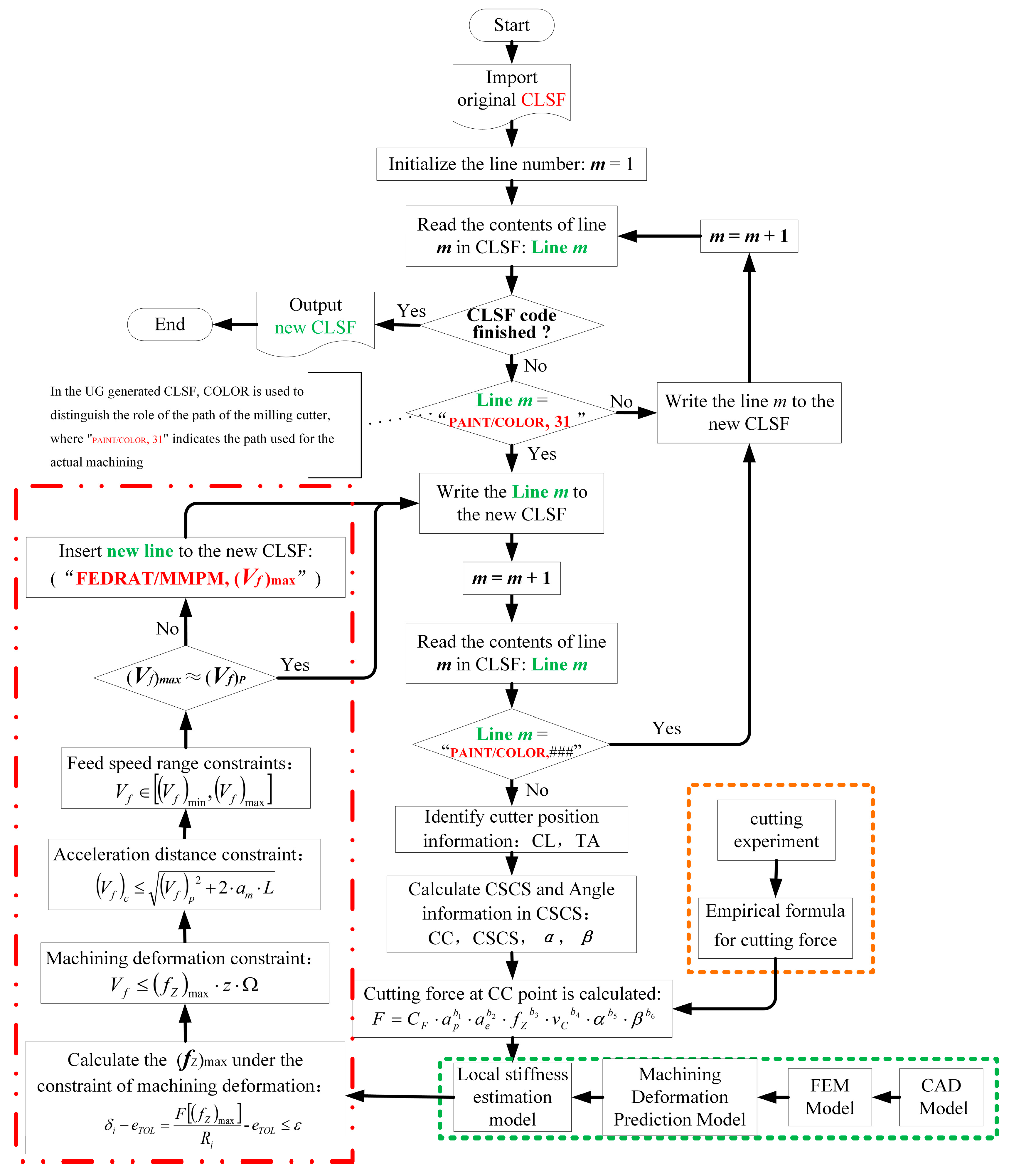
Figure 1.
Offline Feed-rate Scheduling Method for the Thin-wall Finishing Process.
References
- Kurt, M.; Bagci, E. Feedrate optimisation/scheduling on sculptured surface machining: A comprehensive review, applications and future directions. Int. J. Adv. Manuf. Technol. 2011, 55, 1037–1067.
- Adams, O.; Klocke, F.; Schwenzer, M.; Stemmler, S.; Abel, D. Model-based predictive force control in milling—System identification. Procedia Technol. 2016, 26, 214–220.
- Han, Z.; Jin, H.; Fu, Y.; Fu, H. Cutting deflection control of the blade based on real-time feedrate scheduling in open modular architecture CNC system. Int. J. Adv. Manuf. Technol. 2017, 90, 2567–2579.
- Jang, D.; Kim, K.; Jung, J. Voxel-based virtual multi-axis machining. Int. J. Adv. Manuf. Technol. 2000, 16, 709–713.
- Layegh, K.S.E.; Erdim, H.; Lazoglu, I. Offline force control and feedrate scheduling for complex free form surfaces in 5-axis milling. Procedia CIRP 2012, 1, 96–101.
- Woo, W.-S.; Curtis, D.; Bagni, C.; Lee, C.-M.; Lee, J.-H.; Kim, D.-H. Productivity enhancement of aircraft turbine disk using a two-step strategy based on tool-path planning and NC-code optimization. Metals 2022, 12, 567.
- Käsemodel, R.B.; de Souza, A.F.; Voigt, R.; Basso, I.; Rodrigues, A.R. CAD/CAM interfaced algorithm reduces cutting force, roughness, and machining time in free-form milling. Int. J. Adv. Manuf. Technol. 2020, 107, 1883–1900.
- Ghosh, T.; Wang, Y.; Martinsen, K.; Wang, K. A surrogate-assisted optimization approach for multi-response end milling of aluminum alloy AA3105. Int. J. Adv. Manuf. Technol. 2020, 111, 2419–2439.
- Park, H.; Qi, B.; Dang, D.; Park, D.Y. Development of smart machining system for optimizing feedrates to minimize machining time. J. Comp. Des. Eng. 2018, 5, 299–304.
- Wang, L.P.; Yuan, X.; Si, H.; Duan, F.Y. Feedrate scheduling method for constant peak cutting force in five-axis flank milling process. Chin. J. Aeronaut. 2020, 33, 2055–2069.
- Zhang, Z.; Luo, M.; Zhang, D.; Wu, B. A force-measuring-based approach for feed rate optimization considering the stochasticity of machining allowance. Int. J. Adv. Manuf. Technol. 2018, 97, 2545–2556.
- Osorio-Pinzon, J.C.; Abolghasem, S.; Marañon, A.; Casas-Rodriguez, J.P. Cutting parameter optimization of Al-6063-O using numerical simulations and particle swarm optimization. Int. J. Adv. Manuf. Technol. 2020, 111, 2507–2532.
- Xu, G.; Chen, J.; Zhou, H.; Yang, J.; Hu, P.; Dai, W. Multi-objective feedrate optimization method of end milling using the internal data of the CNC system. Int. J. Adv. Manuf. Technol. 2019, 101, 715–731.
- Xie, J.; Zhao, P.; Hu, P.; Yin, Y.; Zhou, H.; Chen, J.; Yang, J. Multi-objective feed rate optimization of three-axis rough milling based on artificial neural network. Int. J. Adv. Manuf. Technol. 2021, 114, 1323–1339.
- Wu, B.; Zhang, Y.; Liu, G.; Zhang, Y. Feedrate optimization method based on machining allowance optimization and constant power constraint. Int. J. Adv. Manuf. Technol. 2021, 115, 3345–3360.
- Du, X.; Huang, J.; Zhu, L.-M.; Ding, H. An error-bounded B-spline curve approximation scheme using dominant points for CNC interpolation of micro-line toolpath. Robot. Comput. Integr. Manuf. 2020, 64, 101930.
- Li, H.; Jiang, X.; Huo, G.; Su, C.; Wang, B.; Hu, Y.; Zheng, Z. A novel feedrate scheduling method based on Sigmoid function with chord error and kinematic constraints. Int. J. Adv. Manuf. Technol. 2022, 119, 1531–1552.
- Song, D.N.; Ma, J.W.; Zhong, Y.G.; Xiao, D.; Yao, J.J.; Zhou, C. A fully real-time spline interpolation algorithm with axial jerk constraint based on FIR filtering. Int. J. Adv. Manuf. Technol. 2021, 113, 1873–1886.
- Zhang, Y.; Ye, P.; Zhao, M.; Zhang, H. Dynamic feedrate optimization for parametric toolpath with data-based tracking error prediction. Mech. Syst. Signal Process. 2019, 120, 221–233.
- Lamikiz, A.; López de Lacalle, L.N.; Sánchez, J.A.; Salgado, M.A. Cutting force estimation in sculptured surface milling. Int. J. Mach. Tools Manuf. 2004, 44, 1511–1526.
- Calleja, A.; Alonso, M.A.; Fernández, A.; Tabernero, I.; Ayesta, I.; Lamikiz, A.; López de Lacalle, L.N. Flank milling model for tool path programming of turbine blisks and compressors. Int. J. Prod. Res. 2014, 53, 3354–3369.
- Calleja, A.; Bo, P.; González, H.; Bartoň, M.; López de Lacalle, L.N. Highly accurate 5-axis flank CNC machining with conical tools. Int. J. Adv. Manuf. Technol. 2018, 97, 1605–1615.
- Salgado, M.A.; López de Lacalle, L.N.; Lamikiz, A.; Muñoa, J.; Sánchez, J.A. Evaluation of the stiffness chain on the deflection of end-mills under cutting forces. Int. J. Mach. Tools Manuf. 2005, 45, 727–739.
- López de Lacalle, L.N.; Lamikiz, A.; Sánchez, J.A.; Salgado, M.A. Toolpath selection based on the minimum deflection cutting forces in the programming of complex surfaces milling. Int. J. Mach. Tools Manuf. 2007, 47, 388–400.
- Hou, Y.; Zhang, D.; Zhang, Y.; Wu, B. The variable radial depth of cut in finishing machining of thin-walled blade based on the stable-state deformation field. Int. J. Adv. Manuf. Technol. 2021, 113, 141–158.
- Wang, J.; Ibaraki, S.; Matsubara, A. A cutting sequence optimization algorithm to reduce the workpiece deformation in thin-wall machining. Precis. Eng. 2017, 50, 506–514.
- Campa, F.J.; Lopez de Lacalle, L.N.; Celaya, A. Chatter avoidance in the milling of thin floors with bull-nose end mills: Model and stability diagrams. Int. J. Mach. Tools Manuf. 2011, 51, 43–53.
- Rozylo, P.; Debski, H. Effect of eccentric loading on the stability and load-carrying capacity of thin-walled composite profiles with top-hat section. Compos. Struct. 2020, 245, 112388.
- Wysmulski, P.; Debski, H.; Falkowicz, K.; Rozylo, P. The influence of load eccentricity on the behavior of thin-walled compressed composite structures. Compos. Struct. 2019, 213, 98–107.
- Hailong, M.; Aijun, T.; Shubo, X.; Tong, L. Finite element simulation of bending thin-walled parts and optimization of cutting parameters. Metals 2023, 13, 115.
More