Your browser does not fully support modern features. Please upgrade for a smoother experience.
Please note this is a comparison between Version 2 by Jessie Wu and Version 1 by Mohammad Abu Hasan Khondoker.
Copper, due to its high thermal and electrical conductivity, is used extensively in many industries such as electronics, aerospace, etc.
- : pure copper
- material extrusion
- additive manufacturing
- process
- Extrusion 3D printing
- pure copper
1. 3D Printing Processes
1.1. PFellet-fed SPcrew-Based Printing Process
Singh et al. [22,37][1][2] used a screw-based extrusion 3D printer, (model: ExAM 255, AIM3D GmbH, Rostock, Germany), that uses a pneumatically powdered piston with a hopper to continuously push the pellets into the extruder. The material was extruded from a hardened steel nozzle with a 0.4 mm diameter at an extrusion temperature of 196 °C. The other printing parameters were a layer thickness of 0.05 mm, extrusion width of 0.51 mm, 65% overlap, bed temperature of 60 °C, nozzle movement speed of 20 mm/s, 100% infill density, and extrusion flow rate of 120% of the usual value. Figure 1a depicts the schematic diagram for the process.
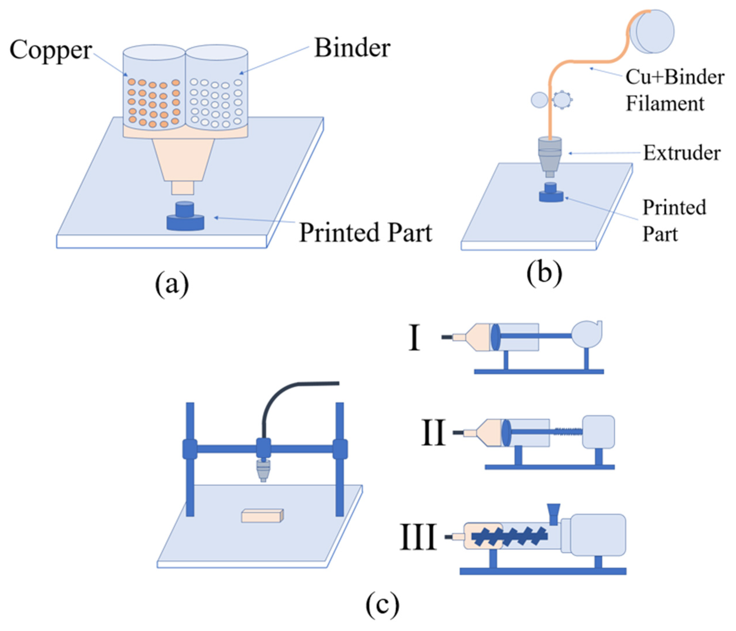
Figure 1.
Schematic diagrams for (
a) PFSP, (
) pellet-fed screw-based printing (PFSP), (
b) FFRP, and (
) filament-fed roller-based printing (FFRP), and (
c)-(I) DIWP with pneumatic dispenser (
)-(I) direct-ink write-based printing (DIWP) with pneumatic dispenser (
c
)-(II), piston-based DIWP (
c
)-(III) and screw-based DI.WP.
1.2. FFRP Process
1.2. Filament-Fed Roller-Based Printing Process
Rodriguez et al. [9][3] and Cañadilla et al. [5][4] used a commercially available system (model: Metal X, Markforged, Watertown, MA, USA) with proprietary materials. Markforged’s atomic diffusion additive manufacturing (ADAM) is an FFRP technique, that was used to print pure copper parts [9][3]. This system uses a proprietary binder system and utilizes separate units for chemical de-binding and thermal de-binding/sintering [5,9][3][4]. When using this technique, two different filaments are employed: the copper filament is used to print the parts, and a ceramic filament is utilized to print support structures [5][4].
Gonzalez-Gutierrez et al. [47][5] used a different system, (model: X1000, German RepRap GmbH, Feldkirchen, Germany) with different print settings such as a nozzle diameter of 0.6 mm, printing speed of 30 mm/s, layer height of 0.3 mm, bed temperature of 90 °C and extrusion temperature of 240 °C. To produce a high-quality filament, a single-screw extruder system with copper and binder feeding in different temperature zones was used.
Figure 1b shows a general schematic diagram for the process.
1.3. DIWP Process
1.3. Direct-Ink Write-Based Printing Process
Zhao et al. loaded the paste in a syringe tube of a pneumatic dispenser, and printed using Teflon sheets for easy demolding. Once the solvent evaporation from a prior printed layer was complete, the next layer was printed atop the previous layer. Yan et al. [49][6] developed a custom paste-injection 3D printing system consisting of a 3D platform and a 0.3 mm diameter syringe-based dispensing system.
Hong et al. [51][7] developed a screw-based paste extruder that was integrated with a typical desktop 3D printer using a hose and syringe-based deposition head. This system allows the feeding of a highly viscous metal paste and the printing of 3D copper parts.
Ren et al. [50][8] also developed a custom piston-based extrusion 3D printer that has a heated syringe to maintain the rheology of the slurry-like molten feedstock during printing. First, copper powder mixed with an organic binder is heated and crushed to prepare the feedstock which is then used to 3D-print green parts using the the following parameters: extrusion temperature: 160 °C; extrusion head speed: 360 mm/min; piston speed: 0.047 mm/s; nozzle diameter: 2 mm. Then, thermal de-binding was performed at 450 °C followed by sintering at 1083 °C.
Figure 31c shows a general schematic diagram for the processes.
2. De-Binding and Sintering
2.1. For Parts Printed by PFSP
2.1. For Parts Printed by Pellet-Fed Screw-Based Printing
Singh et al. [22][1] performed solvent de-binding by submerging the printed green parts under water for 14 h to dissolve PEG, followed by drying at 100 °C for 2 h in an oven. After that, the parts were subjected to thermal de-binding using a vertical dilatometer by heating them to 500 °C at a rate of 1 °C/min and holding them at that temperature for 1 h to remove wax. The parts were sintered by continuing heating to 950 °C at the a rate of 4 °C/min, holding them at that temperature for 3 h, then again heating them to 1030 °C at the a rate of 4 °C/min, holding them again for 3 h, and finally cooling them down at a rate of 6 °C/min. Both thermal de-binding and sintering were performed in the presence of a gas flow containing 96% He and 4% H2. Figure 2a shows the thermal profile observed during the de-binding and sintering process [22][1]. While in this restudyearch, Singh et al. used the same heating cycle for thermal de-binding and sintering, in another study [37][2], the same researchers used two separate heating cycles for both thermal de-binding and sintering, as shown in Figure 2b.
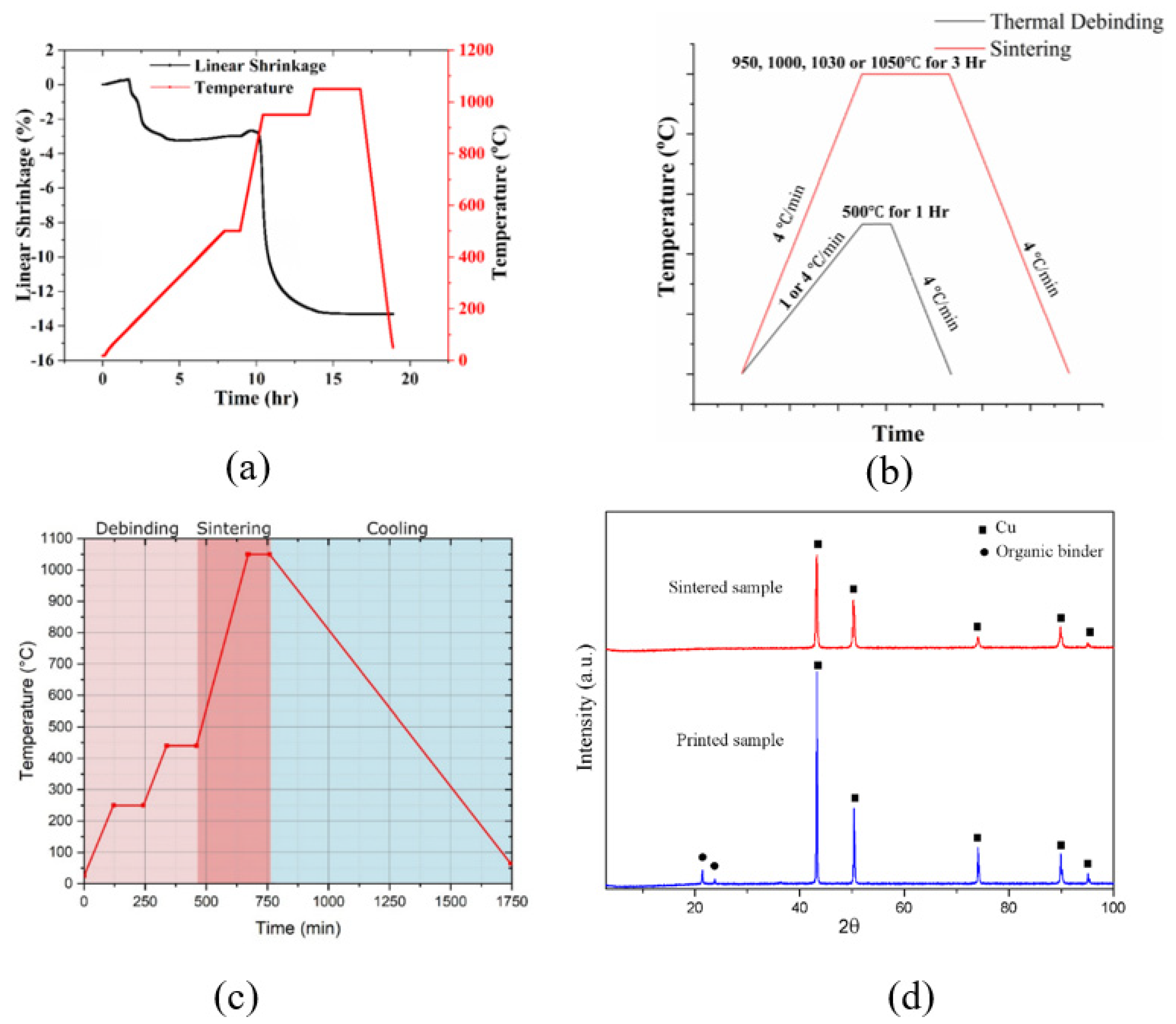
Figure 2. Thermal profiles of the de-binding and sintering processes (a) [22][1] © Elsevier, used with permission (b) [37][2] © Springer, used under CC-BY (c) [47][5] © MDPI, and used under CC-BY (d). Comparison of the XRD patterns of the printed specimen and the sintered specimen [50][8] © MDPI. Used under CC-BY.
The binder system of Gonzalez-Gutierrez et al. [47][5] comprised a soluble cyclohexane TPE and a grafted polyolefin (gPO) as an insoluble backbone. Solvent de-binding was conducted by submerging the parts in cyclohexane at 60 °C to remove the TPE, followed by drying for around 4 h in a fume hood at ambient temperature. After that, the specimens went through thermal de-binding and sintering in a hydrogen-filled furnace. As Figure 42c depicts, the temperature was raised to 250 °C (with holding for 1 h) and 450 °C (with holding for 1 h) for two-stage de-binding process. For sintering, the parts were heated to 1050 °C and held for 1 h, followed by being cooled. All heating cycles were performed at a rate of 2 °C/min.
2.2. For Parts Printed by FFRP
2.2. For Parts Printed by Filament-Fed Roller-Based Printing
Both Rodriguez et al. [9][3] and Cañadilla et al. [5][4] used Markforged’s Wash-1 unit for solvent de-binding to remove Markforged’s proprietary solvent (Opteon SF-79) from the printed green parts. For thermal de-binding and sintering in the same cycle, both groups used Markforged’s Sinter-1 unit that [9][3] can heat up to 1300 °C. First, it was heated up to a certain de-binding temperature and then maintained at that temperature for a specific amount of time to ensure the complete removal of the high-molecular-weight (HMW) polymer binder. Then, the temperature was increased to the sintering temperature followed by being held for the holding time. Lastly, it was cooled down to the room temperature. The entire thermal cycle took place under protective atmospheric conditions and lasted 30 h in total. The thermal de-binding stage involved a 2.8% H2 and 97.8% Ar atmosphere, and the sintering and cooling steps were carried out in a pure Argon environment. After the full heating cycle, the final metallic pure copper components were produced [5][4].
2.3. For Parts Printed by DIWP
2.3. For Parts Printed by Direct-Ink Write-Based Printing
The organic solvent used in DIWP does not require a solvent de-binding step, as the volatile solvent evaporates during and after printing in ambient temperature. While some researchers conducted simultaneous thermal de-binding and sintering processes in one single step, others performed two different but sequential steps for thermal de-binding and sintering. For example, Zhao et al. [48][9] used a furnace flooded with 95% N2 and 5% H2 to heat the printed green parts to 1000 °C and cooled them at a rate of 5 °C/min after holding them at the peak temperature for 2 h. Yan et al. [49][6] performed sintering of copper green parts at various temperatures (750 °C, 800 °C, 850 °C, 900 °C, 950 °C, 1000 °C, and 1050 °C) where the temperature was raised at a rate of 10 °C/min. They found that a minimum temperature of 950 °C with a holding period of 120 min was necessary to realize fully sintered copper parts. Similarly, Hong et al. [51][7] dried printed copper green parts in air at ambient temperature, then subjected them to a heat treatment with charcoal in a box furnace at 950 °C for two hours.
While Ren et al. [50][8] also did not require a solvent de-binding step, they applied a two-stage post-processing step in a furnace under a vacuum. First, the copper green parts were heated to 500 °C at a rate of 2 °C/min, held at that temperature for 2.5 h, then heated again to 1083 °C at a rate of 3 °C/min and held at that temperature for 3 h. The X-ray diffraction (XRD) analysis, shown in Figure 2d, exhibits the disappearance of peaks associated with the organic binder after sintering.
References
- Singh, G.; Missiaen, J.M.; Bouvard, D.; Chaix, J.M. Copper Extrusion 3D Printing Using Metal Injection Moulding Feedstock: Analysis of Process Parameters for Green Density and Surface Roughness Optimization. Addit. Manuf. 2021, 38, 1778.
- Singh, G.; Missiaen, J.-M.; Bouvard, D.; Chaix, J.-M. Copper Additive Manufacturing Using MIM Feedstock: Adjustment of Printing, Debinding, and Sintering Parameters for Processing Dense and Defectless Parts. Int. J. Adv. Manuf. Technol. 2021, 115, 449–462.
- Rodriguez, J.; Vicente, J.I.; Ezeiza, J.C.; Zuriarrain, A.; Arrazola, P.J.; Badiola, X.; Dominguez, E.; Soler, D. Mechanical and Electrical Properties of Additively Manufactured Copper. IOP Conf. Ser. Mater. Sci. Eng. 2021, 1193, 012034.
- Cañadilla, A.; Romero, A.; Rodríguez, G.P.; Caminero, M.Á.; Dura, Ó.J. Mechanical, Electrical, and Thermal Characterization of Pure Copper Parts Manufactured via Material Extrusion Additive Manufacturing. Materials 2022, 15, 4644.
- Gonzalez-Gutierrez, J.; Cano, S.; Ecker, J.V.; Kitzmantel, M.; Arbeiter, F.; Kukla, C.; Holzer, C. Bending Properties of Lightweight Copper Specimens with Different Infill Patterns Produced by Material Extrusion Additive Manufacturing, Solvent Debinding and Sintering. Appl. Sci. 2021, 11, 7262.
- Yan, X.; Hao, L.; Xiong, W.; Tang, D. Research on Influencing Factors and Its Optimization of Metal Powder Injection Molding without Mold via an Innovative 3D Printing Method. RSC Adv. 2017, 7, 55232–55239.
- Hong, S.; Sanchez, C.; Du, H.; Kim, N. Fabrication of 3D Printed Metal Structures by Use of High-Viscosity Cu Paste and a Screw Extruder. J. Electron. Mater. 2015, 44, 836–841.
- Ren, L.; Zhou, X.; Song, Z.; Zhao, C.; Liu, Q.; Xue, J.; Li, X. Process Parameter Optimization of Extrusion-Based 3D Metal Printing Utilizing PW-LDPE-SA Binder System. Materials 2017, 10, 305.
- Zhao, Y.; Gao, W.; Xi, J.; Li, H.; Ren, F. Development of Copper Powder Paste for Direct Printing and Soft Mold Casting. Addit. Manuf. 2020, 31, 992.
More