Your browser does not fully support modern features. Please upgrade for a smoother experience.
Please note this is a comparison between Version 2 by Catherine Yang and Version 1 by Petr Korba.
Many researchers have focused on two-stage converter control (TSCC) and single-stage converter (SSC) control for FCS stability enhancement, and suggested that SSC architectures are superior in performance, unlike the TSCC methods. SSC control techniques provide more accuracy in grid stability improvement via the provision of inertial support through virtual synchronous machine (VSM) control of the rectifier converter.
- electric vehicle
- fast charging station
- grid stability
- virtual synchronous machine
1. Alternating-Current-Based Control (ACBC) Technique
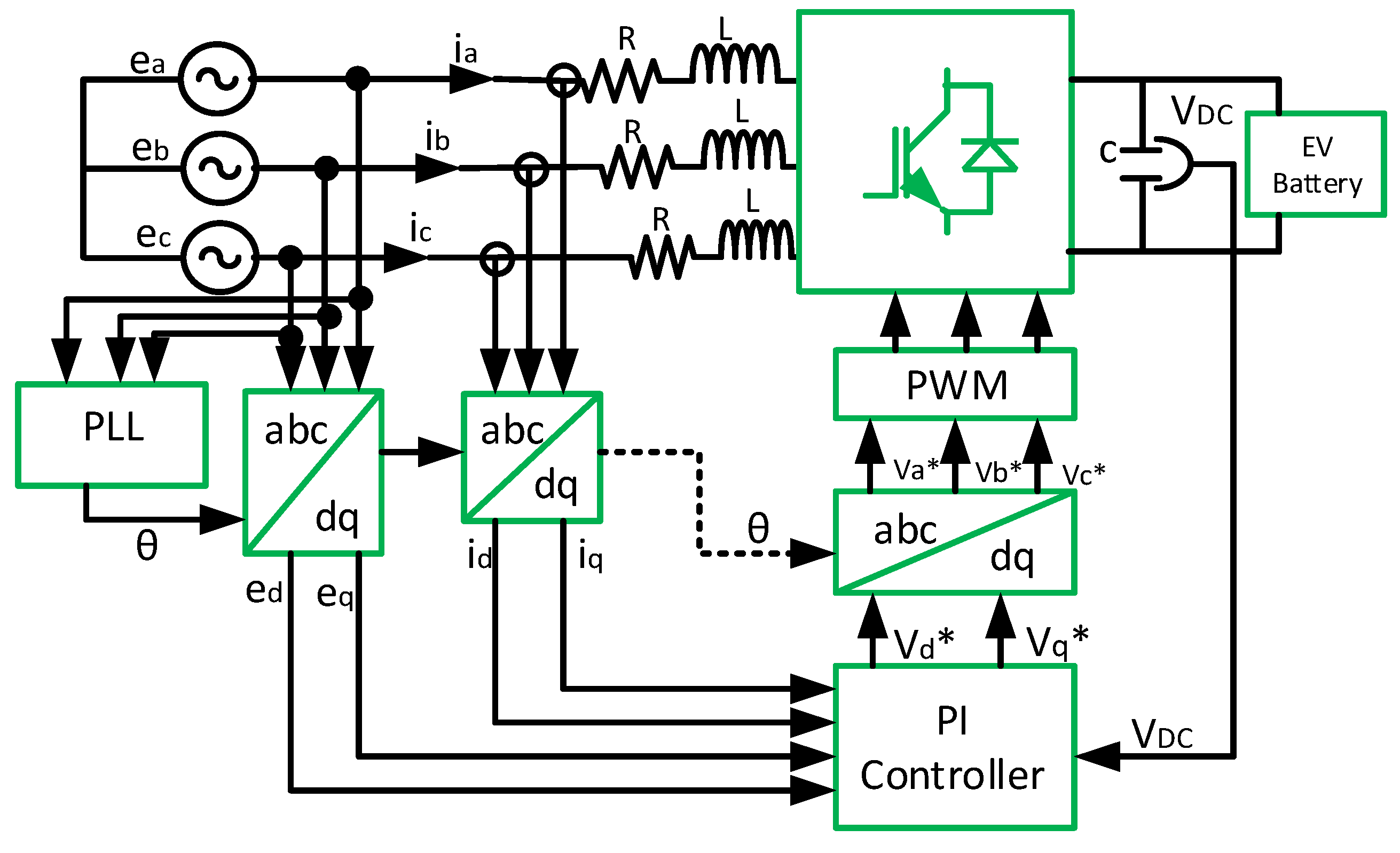
One of the examples of SSC control techniques is shown in Figure 11. This technique consists of a rectifying converter [74][1] that is implemented to mimic the virtual synchronous machine’s (VSM) behavior [76][2]. However, the report in [77][3] proposed an interleaved switching strategy for rectifier control using the PI controller for current control to ensure the reduction in the magnitude of the ripple current injection. This strategy achieved a harmonic distortion reduction in grid-side currents and had a ripple-free DC-side current without sacrificing the efficiency of the FCS [77,78][3][4]. Conversely, the report in [22][5] proposed the DC-side voltage integration with time filtering of the instantaneous value of current control for grid-side harmonic cancellation at the PCC. The report in [20][6] proposed an independent single control variable of the grid sinusoidal current waveforms for injected power and voltage regulation at the PCC. This was achieved by extracting the grid phase angle using the dq transformation of input voltages and the output DC voltage tracking control strategy [79][7].
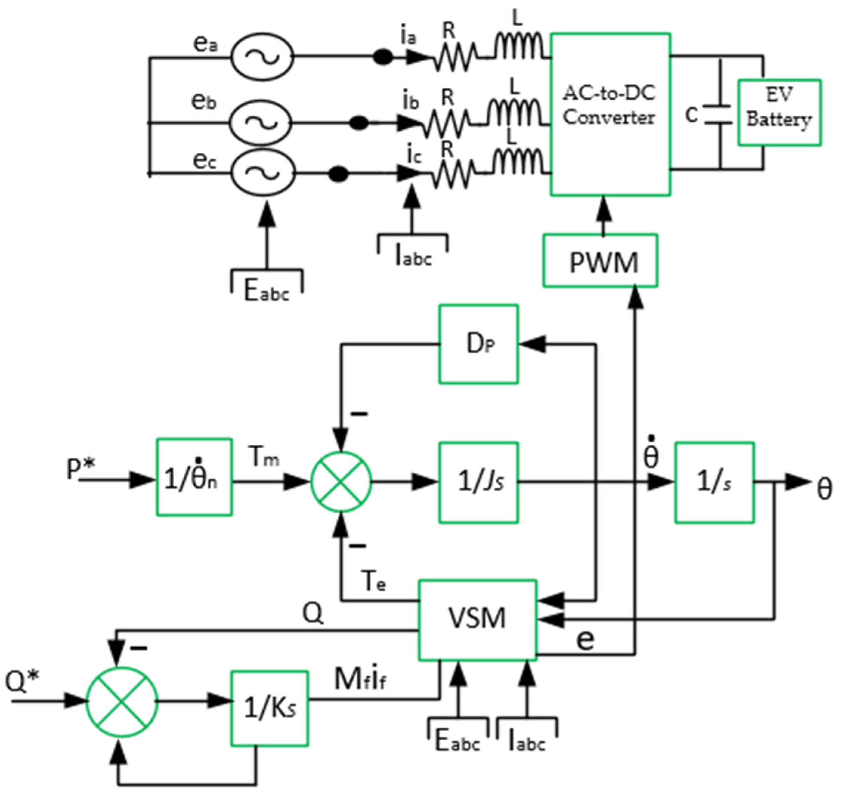
In a related development, the authors in [78][4] presented a different control approach for DC-link voltage and ripple current cancellation for the rectifier DC output. This control strategy was able to maintain the soft switching of both AC-side and DC-side switches across the voltage grid cycle at the PCC for different load conditions [75,78][4][9]. However, a major drawback of a slow response was observed in [74,78][1][4] under increased EV loads, but this shortcoming was suggested to be due to the PI controller [74,75,76][1][2][9]. In the case of VSM, as shown in Figure 12, where it is deployed to mimic a VSM’s performance, it offers a controlled power factor and stabilized supply frequency irrespective of changes at the PCC [80][10]. This control strategy ensures frequency and power control by using the virtual amplitude compensator (VAC) [81][11]. This approach is often deployed with a PI controller to achieve a margin of stability in a weak grid scenario via the virtual shaft angle with frequency adaptation, and to update the filter coefficient of synchronous frequency for frequency regulation at the PCC [82][12].
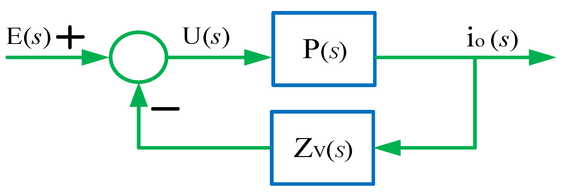
The VSM control strategy can also be implemented through other approaches, such as the line impedance approach [83][13]. The line impedance approach helps to reshape the quadrature axis with positive resistance in the lower frequency band to ensure regulated frequency at the PCC [82,84][12][14]. However, it must be applied by feedforwarding both the direct and quadrature axes’ grid voltages with respect to the reference current [84][14]. Additionally, the tracking of zero steady-state errors and the damping of the torsion oscillation of the system must be achieved at a predetermined frequency [83,84][13][14]. In addition, the virtual flux control (VFC) strategy was used in [85][15] for direct power control and input voltage source estimation for a three-phase-based FCS to regulate line current harmonics, the DC-link voltage output, and the power factor through the control of the instantaneous active power and the reactive power at the input [85][15]. Additionally, the authors in [86][16] presented the virtual harmonic impedance (VHI) strategy to mitigate spikes in switching harmonics and voltage. This strategy implements a current controller in the rectification stage of the FCS to avoid power losses, while exhibiting the behavior of a real impedance, as shown in Figure 13 [87][17]. It creates an equal output impedance to resistance and inductance [88,89][18][19]. In this case, the virtual harmonic impedance, (ZV(s)ZVs), is the sum of virtual harmonic resistance and virtual inductance [89][19]: E(s)Es is the input and io(s)io(s) is the output current parameter, while P(s)Ps is the transfer function and ZVZV is virtual harmonic impedance [87][17]. Despite the power factor improvement, direct power, and frequency control in this SSC strategy, it presents some very serious issues related to power losses and frequency fluctuation, as reported in [77[3][17],87], during multiple FCS operations at the PCC, and this call for further research. Some of the most recent achievements and contributions in SSC control techniques are summarized in the next subsection.
2. Summary of the Most Recent State-of-the-Art Achievements in SSC Strategy
The most recent approaches in the ACBC strategy were presented in [80,90][10][20]. This strategy allows for virtual amplitude compensation (VAC) at the rectification stage of the FSC [91,92][21][22]. In this case, the voltage amplitude was maintained within a standard of allowable margin by the VSM controller to fast-track power control of the EV battery charging process [93,94][23][24]. It ensured that reactive power flowed towards the grid in such a way that the amplitude of the reference current vector was adaptable to the FCS’ power rating regardless of the grid condition [80,95][10][25]. Similarly, [86,89][16][19] presented the concept of virtually varying the effective line impedance at the harmonic frequency in such a way that the influence of mismatched line impedance on nonlinear FCS load distribution was reduced [96,97][26][27]. This strategy avoids losses, while mimicking the behavior of real impedance [87,88][17][18]. Additionally, the latest approach in [98][28] proposed the implementation of the flux compensation strategy at the rectification stage of the FCS through direct power control [98,99][28][29]. This approach helps to regulate line current harmonics, power factor and DC-link voltage by controlling instantaneous active power and reactive power input [85,100][15][30]. This strategy also allows for the synchronization of the voltage of the FCS rectifier with the voltage condition at the PCC [101][31].
A comparison of the various contributions for and drawbacks of SSC control techniques from the literature is shown in Table 21.
Table 21.
Comparison of the most recent trends in SSC techniques for FCS.
| No. | Ref. | VSM Technique | Strategy | Contribution | Drawbacks | Control Complexity |
|---|---|---|---|---|---|---|
| 1 | [90][20] | Synchronous generator (SG)-based model | VAC-PI | Accurately simulates electromagnetic characteristics of SG and requires no frequency derivative synchronization. | Possesses weak resistance to interference due to voltage open-loop control and numerical instability issues. | Very high |
| 2 | [80,91][10][21] | Swing equation-based | VAC-PI | Provides frequency adaptability to sudden changes in load profile. | Excitation control issues; prone to synchronous resonance; weak stability during multiple FCS operations. | Simple |
| 3 | [86,89][16][19] | Droop-based technique | VHI-PI | Adaptable to changes in single FCS load and enhances stability of system. | Power sharing accuracy depends on rectifier output and line impedance. | Simple |
| 4 | [88][18] | Frequency–power response-based | VHI-PI | Provides configurable output impedance and highly suitable for weak grid operation. |
Stability margins are reduced with higher values of virtual resistance and it is hard to regulate dynamics. | High |
| 5 | [98,99][28][29] | Frequency–power response-based | VFC-PI | Provides fast response and frequency support in single FCS load. | Drift and saturation effect due to DC offset in the integrated signals lag voltage by 90° phase shift. |
Simple |
| 6 | Proposed | Droop-based SOC technique |
VSM-SOC | Adaptability to EV battery SOC. Fast transient response. Active and reactive power decoupling. Frequency and voltage regulation at PCC. Adaptable to SOC charge and discharge limit condition. It allows current limiting capability. |
NIL | Simple |
References
- Blahnik, V.; Stepanek, J.; Jara, M.; Talla, J. Ultra-fast charging station for public transport vehicles. In Proceedings of the 2017 43rd Annual Conference of the IEEE Industrial Electronics Society, Beijing, China, 29 October–1 November 2017.
- Ma, Z.; Zhong, Q.C.; Yan, J.D. Synchronverter-based control strategies for three-phase PWM rectifiers. In Proceedings of the 2012 7th IEEE Conference on Industrial Electronics and Applications, Singapore, 18–20 July 2012; pp. 225–230.
- Ahmed, M.A.; Dasika, J.D.; Saeedifard, M.; Wasynczuk, O. Interleaved Swiss Rectifiers for Fast EV/PHEV Battery Chargers. In Proceedings of the 2014 IEEE Applied Power Electronics Conference and Exposition, Fort Worth, TX, USA, 16–20 March 2014.
- Kumar, M.; Pramanick, S.; Panigrahi, B.K. Reduction in Circulating Current With Improved Secondary Side Modulation, Isolated Current-Fed Half Bridge AC–DC Converter. IEEE Trans. Power Electron. 2021, 37, 5625–5636.
- Zhang, D.; Lin, H.; Zhang, Q.; Kang, S.; Lu, Z. Analysis, Design, and Implementation of a Single-Stage Multipulse Flexible-Topology Thyristor Rectifier for Battery Charging in Electric Vehicles. IEEE Trans. Energy Convers. 2019, 34, 47–57.
- Blinov, A.; Zinchenko, D.; Rabkowski, J.; Wrona, G.; Vinnikov, D. Quasi Single-Stage Three-Phase Filterless Converter for EV Charging Applications. IEEE Open J. Power Electron. 2021, 3, 51–60.
- Ehsani, M.; Singh, K.V.; Bansal, H.O.; Mehrjardi, R.T. State of the Art and Trends in Electric and Hybrid Electric Vehicles. Proc. IEEE 2021, 109, 967–984.
- Cortes, P.; Vancu, M.F.; Kolar, J.W. Swiss Rectifier Output Voltage Control with Inner Loop Power Flow Programming (PFP). In Proceedings of the 2013 IEEE 14th Workshop on Control and Modeling for Power Electronics, Salt Lake City, UT, USA, 23–26 June 2013.
- Collin, R.; Miao, Y.; Yokochi, A.; Enjeti, P.; Von Jouanne, A. Advanced electric Vehicle Fast-Charging Technologies. Energies 2019, 12, 1839.
- Mandrile, F.; Cittanti, D.; Mallemaci, V.; Bojoi, R. Electric vehicle ultra-fast battery chargers: A boost for power system stability? World Electr. Veh. J. 2021, 12, 16.
- Dong, W.; Liu, K.; Chen, L. A novel frequency-changer control strategy based on a virtual synchronous motor. CSEE J. Power Energy Syst. 2019, 5, 199–205.
- Cheema, K.M.; Chaudyhary, N.I.; Tahir, M.F.; Mehmood, K.; Mudassir, M.; Kamran, M.; Milyani, A.H.; Elbarbary, Z.M.S. Virtual synchronous generator: Modifications, stability assessment and future applications. Energy Rep. 2022, 8, 1704–1717.
- Fang, J.; Li, X.; Li, H.; Tang, Y. Stability Improvement for Three-Phase Grid-Connected Converters Through Impedance Reshaping in Quadrature-Axis. IEEE Trans. Power Electron. 2018, 33, 8365–8375.
- Guan, Y.; Guerrero, J.M.; Zhao, X.; Vasquez, J.C.; Guo, X. A New Way of Controlling Parallel-Connected Inverters by Using Synchronous-Reference-Frame Virtual Impedance Loop—Part I: Control Principle. IEEE Trans. Power Electron. 2016, 31, 4576–4593.
- Roslan, N.F. Control Strategy of Grid Connected Power Converter based on Virtual Flux Approach. Ph.D. Thesis, Universitat Politècnica de Catalunya, Barcelona, Spain, 2021.
- Roldán-Pérez, J.; Rodríguez-Cabero, A.; Prodanovic, M. Harmonic virtual impedance design for a synchronverter-based battery interface converter. In Proceedings of the 2017 6th International Conference on Renewable Energy Research and Applications, San Diego, CA, USA, 5–8 November 2017.
- Mohammed, O.O.; Otuoze, A.O.; Salisu, S.; Ibrahim, O.; Rufa’i, N.A. Virtual synchronous generator: An overview. Niger. J. Technol. 2019, 38, 153–164.
- Shin, D.; Lee, J.P.; Yoo, D.W.; Kim, H.J. Stability Improvement of Interleaved Voltage Source Inverters Employing Coupled Inductors for Grid-Connected Applications. IEEE Trans. Ind. Electron. 2015, 62, 6014–6023.
- Bai, S.; Lukic, S.M. Unified active filter and energy storage system for an MW electric vehicle charging station. IEEE Trans. Power Electron. 2013, 28, 5793–5803.
- Sang, W.; Guo, W.; Dai, S.; Tian, C.; Yu, S.; Teng, Y. Virtual Synchronous Generator, a Comprehensive Overview. Energies 2022, 15, 6148.
- Muftau, B.; Fazeli, M. The Role of Virtual Synchronous Machines in Future Power Systems: A Review and Future Trends. Electr. Power Syst. Res. 2022, 206, 107775.
- Mallemaci, V.; Mandrile, F.; Rubino, S.; Mazza, A.; Carpaneto, E.; Bojoi, R. A comprehensive comparison of Virtual Synchronous Generators with focus on virtual inertia and frequency regulation. Electr. Power Syst. Res. 2021, 201, 107516.
- Yang, Z.; Mei, C.; Cheng, S.; Zhan, M. Comparison of Impedance Model and Amplitude-Phase Model for Power-Electronics-Based Power System. IEEE J. Emerg. Sel. Top. Power Electron. 2020, 8, 2546–2558.
- Amorim, T.S.; Carletti, D.; Encarnacao, L.F. Enhanced Virtual Synchronous Generator with Harmonic Current Filtering Capability. In Proceedings of the Industrial Electron Conference, Vitória, Brazil, 4–7 October 2019.
- Yan, X.; Qin, F.; Jia, J.; Zhang, Z.; Li, X.; Sun, Y. Virtual synchronous motor based-control of Vienna rectifier. Energy Rep. 2020, 6, 953–963.
- Sreekumar, P.; Khadkikar, V. A New Virtual Harmonic Impedance Scheme for Harmonic Power Sharing in an Islanded Microgrid. IEEE Trans. Power Deliv. 2016, 31, 936–945.
- Ding, D.; Zhang, G.; Wang, G.; Mijatoviv, Z.N.; Gragicevic, T.; Xu, D. Impedance Reshaping for Inherent Harmonics in PMSM Drives With Small DC-Link Capacitor. IEEE Trans. Power Electron. 2022, 37, 14265–14279.
- He, P.; Li, Z.; Jin, H.; Zhao, C.; Fan, J.; Wu, X. An adaptive VSG control strategy of battery energy storage system for power system frequency stability enhancement. Int. J. Electr. Power Energy Syst. 2023, 149, 109039.
- Yusoff, N.A.; Razali, A.M.; Karim, K.A.; Sutikno, T.; Jidin, A. A concept of Virtual-Flux Direct Power Control of three-phase AC-DC converter. Int. J. Power Electron. Drive Syst. 2017, 8, 1776–1784.
- Wang, A.; Zhang, J. An accurate active power sharing study in virtual flux angle droop method. In Proceedings of the 2017 43rd Annual Conference of the IEEE Industrial Electronics Society, Beijing, China, 29 December–1 January 2017.
- Bi, K.; Xu, Y.; Zeng, P.; Chen, W.; Li, X. Virtual Flux Voltage-Oriented Vector Control Method of Wide Frequency Active Rectifiers Based on Dual Low-Pass Filter. World Electr. Veh. J. 2022, 13, 35.
More