Introduction
Rationale for 3D Printing in Orthopaedics
| Factor | 3D Printing | Conventional Manufacturing |
|---|---|---|
| Advantages |
|
|
| Disadvantages |
|
|
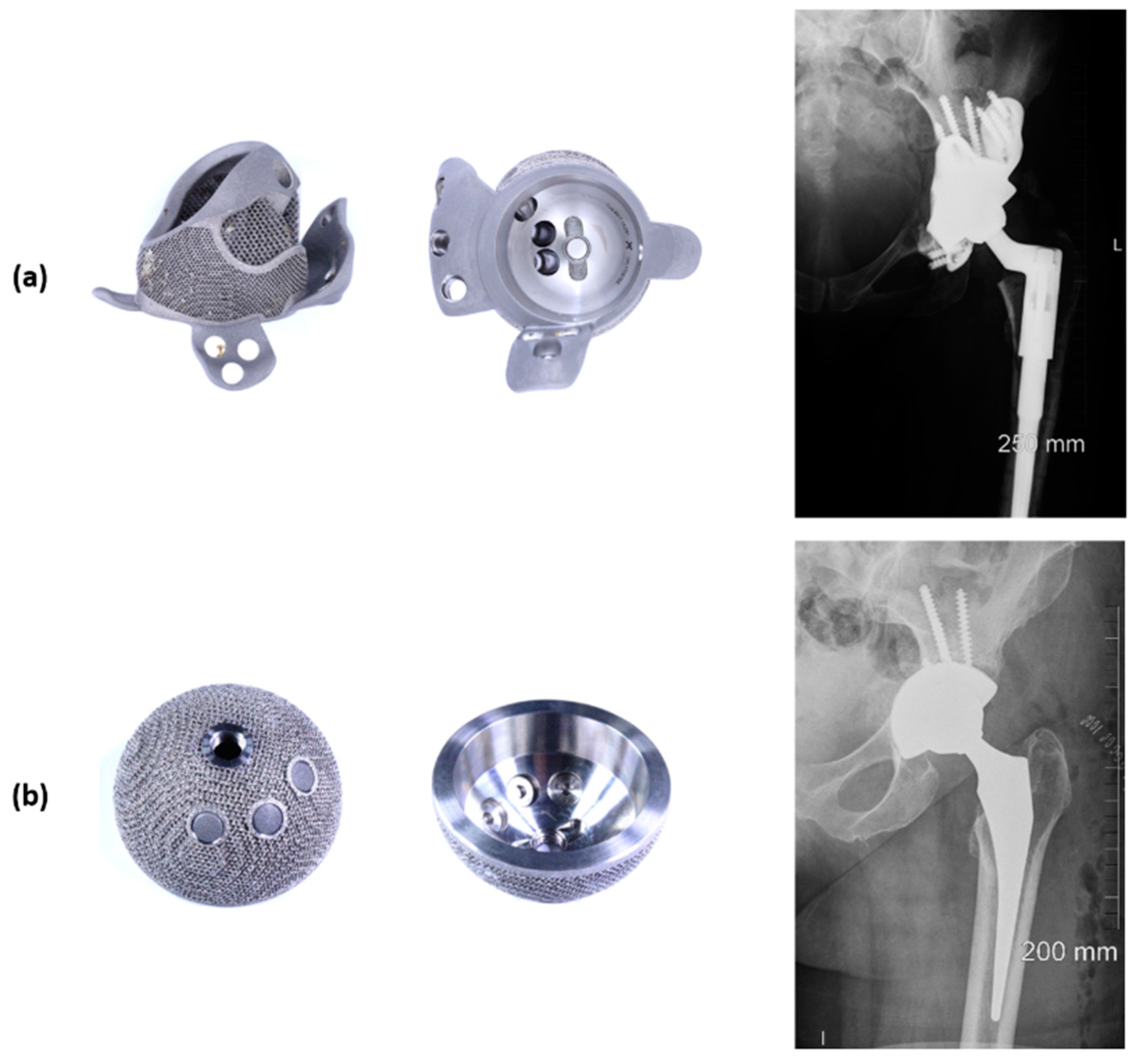
Clinical Rationale for 3D Printed Cups
Engineering Rationale for 3D Printed Cups
3D Printing Manufacturing Process, Limitations and Risks
Manufacturing Process
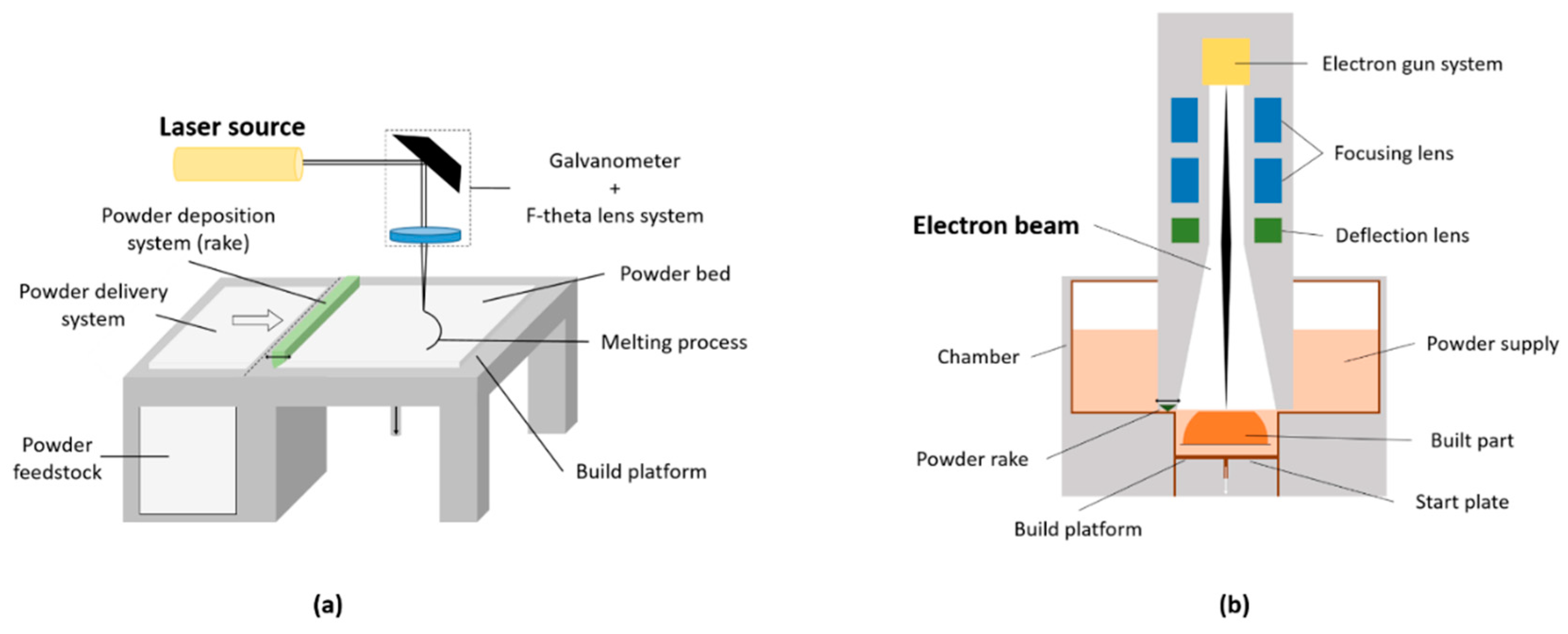
| Features | SLM | EBM |
|---|---|---|
| Heat source | Laser beam (up to 1 kW) | Electron beam (60 kW) |
| Scan speed | Limited by galvanometer inertia | Fast, magnetically driven |
| Powder size | 10–45 µm | 45–106 µm |
| Minimum beam size | 50 mm | 140 mm |
| Beam/melt pool dimension | 0.5–1.5 µm | 2–3 µm |
| Layer thickness | 20–100 µm | 50–200 µm |
| Chamber atmosphere | Argon or nitrogen | Vacuum (+helium) |
| Environment temperature | Build platform at 100–200 °C | Chamber at 400–1000 °C |
| Powder pre-heating | Using infrared or resistive heaters | Using electron beam |
| Surface finish | Excellent to moderate (~20 µm) | Moderate to poor (~35 µm) |
| Residual stresses | Yes | No |
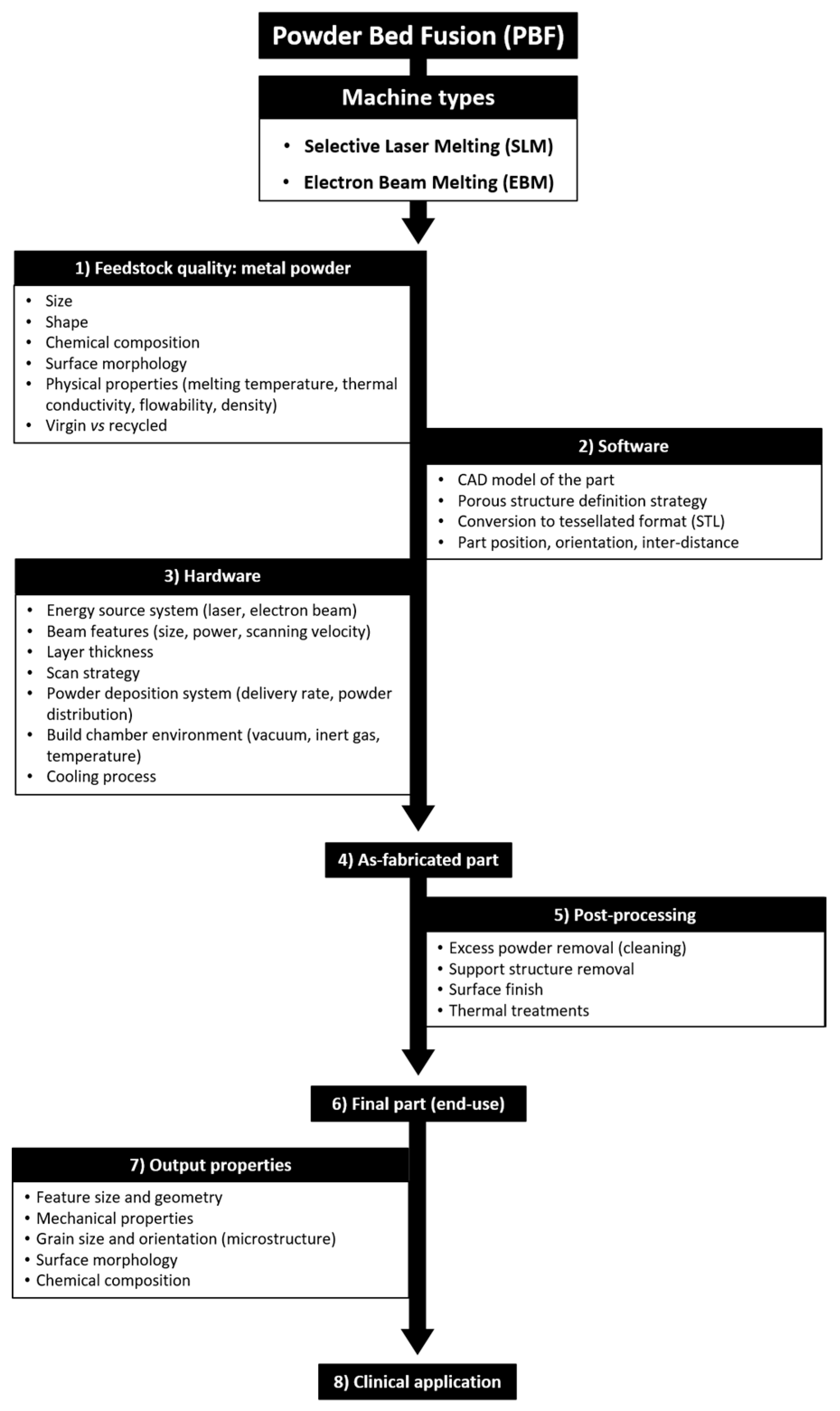
At the end of the building process, the part is considered “as-fabricated” and requires post-processing steps. Excess powder and support structures must be removed; thermal treatment can be applied to reduce residual stresses in the structure and enhance the overall mechanical properties. Machining can also be used to modify the surface finish, influencing the actual part tolerance, minimum feature size and surface roughness of the end-use component. As example, surface roughness is influenced by the layering effect (‘stair-step effect’), by the actual roughness of the powder particles (finer powder means smaller satellites formation) and by post-processing steps. Similarly, the geometrical accuracy depends on the setup of the machine and post-processing treatments [43,44]; it has been suggested that EBM tolerance capability is about ±250/300 µm [53,54].
Limitations and Potential Risks of 3D Printing
References
- Abdel Jaber, S.; Affatato, S. An overview of in vitro mechanical and structural characterization of hip prosthesis components. Clin. Pract. Adv. Clin. Res. Med. Devices 2017, 585–599, doi:10.1007/978-3-319-68025-5_22.
- Bozic, K.J.; Kurtz, S.M.; Lau, E.; Ong, K.; Vail, T.P.; Berry, D.J. The Epidemiology of Revision Total Hip Arthroplasty in the United States. Bone Jt. Surg. Am. Vol. 2009, 91, 128–133, doi:10.2106/JBJS.H.00155.
- Patel, A.; Pavlou, G.; Mújica-Mota, R.E.; Toms, A.D. The epidemiology of revision total knee and hip arthroplasty in England and Wales: A comparative analysis with projections for the United States. A study using the national joint registry dataset. Bone Jt. J. 2015, 97-B, 1076–1081, doi:10.1302/0301-620X.97B8.35170.
- Banerjee, S.; Kulesha, G.; Kester, M.; Mont, M.A. Emerging technologies in arthroplasty: Additive manufacturing. Knee Surg. 2014, 27, 185–191, doi:10.1055/s-0034-1374810.
- Mumith, A.; Thomas, M.; Shah, Z.; Coathup, M.; Blunn, G. Additive manufacturing. Bone Jt. J. 2018, 100-B, 455–460, doi:10.1302/0301-620X.100B4.BJJ-2017-0662.R2.
- Frazier, W.E. Metal additive manufacturing: A review. Mater. Eng. Perform. 2014, 23, 1917–1928, doi:10.1007/s11665-014-0958-z.
- Murr, L.E.; Gaytan, S.M.; Martinez, E.; Medina, F.; Wicker, R.B. Next generation orthopaedic implants by additive manufacturing using electron beam melting. J. Biomater. 2012, 2012, 1–14.
- Morrison, R.J.; Kashlan, K.N.; Flanangan, C.L.; Wright, J.K.; Green, G.E.; Hollister, S.J.; Weatherwax, K.J. Regulatory considerations in the design and manufacturing of implantable 3D-printed medical devices. Transl. Sci. 2015, 8, 594–600, doi:10.1111/cts.12315.
- Orthopaedic Data Evaluation Panel (ODEP). Available online: http://www.odep.org.uk/products.aspx (accessed on 1 April 2019).
- Hothi, H.S.; Berber, R.; Panagiotopoulos, A.C.; Whittaker, R.K.; Rhead, C.; Skinner, J.A.; Hart, A.J. Clinical significance of corrosion of cemented femoral stems in metal-on-metal hips: A retrieval study. Orthop. 2016, 40, 2247–2254, doi:10.1007/s00264-016-3116-4.
- Hothi, H.S.; Berber, R.; Whittaker, R.K.; Blunn, G.W.; Skinner, J.A.; Hart, A.J. The relationship between cobalt/chromium ratios and the high prevalence of head-stem junction corrosion in metal-on-metal total hip arthroplasty. Arthroplasty 2016, 31, 1123–1127, doi:10.1016/j.arth.2015.11.014.
- National Joint Registry for England, Wales, Northern Ireland and the Isle of Man: 15th Annual Report. 2018. Available online: www.njrreports.org.uk (accessed on 1 April 2019)
- Murr, L.E.; Gaytan, S.M.; Medina, F.; Lopez, H.; Martinez, E.; MacHado, B.I.; Hernandez, D.H.; Martinez, L.; Lopez, M.I.; Wicker, R.B.; et al. Next-generation biomedical implants using additive manufacturing of complex cellular and functional mesh arrays. Trans. R. Soc. A Math. Phys. Eng. Sci. 2010, 368, 1999–2032, doi:10.1098/rsta.2010.0010.
- Dennis, D.A. Management of massive acetabular defects in revision total hip arthroplasty. Arthropl. 2003, 18, 121–125, doi:10.1054/arth.2003.50105.
- Jain, S.; Grogan, R.J.; Giannoudis, P.V. Options for managing severe acetabular bone loss in revision hip arthroplasty. A systematic review. Hip Int. 2014, 24, 109–122, doi:10.5301/hipint.5000101.
- Moore, K.D.; McClenny, M.D.; Wills, W.B. Custom Triflange acetabular components for large acetabular defects: Minimum 10-year follow-up. Orthopedics 2018, 16, 1–5, doi:10.3928/01477447-20180213-11.
- Hart, A.J.; Hart, A.; Panagiotopoulou, V.; Henckel, J. Orthopaedic Products News 2017, 178, 22–26.
- Sheth, N.P.; Nelson, C.L.; Springer, B.D.; Fehring, T.K.; Paprosky, W.G. Acetabular bone loss in revision total hip arthroplasty: Evaluation and management. Am. Acad. Orthop. Surg. 2013, 21, 128–139, doi:10.5435/JAAOS-21-03-128.
- Learmonth, I.D.; Young, C.; Rorabeck, C. The operation of the century: total hip replacement. Lancet 2007, 370, 1508–1519, doi:10.1016/S0140-6736(07)60457-7.
- Paprosky, W.G.; Perona, P.G.; Lawrence, J.M. Acetabular defect classification and surgical reconstruction in revision arthroplasty. A 6-year follow-up evaluation. Arthropl. 1994, 9, 33–44, doi:10.1016/0883-5403(94)90135-X.
- Citak, M.; Kochsiek, L.; Gehrke, T.; Haasper, C.; Suero, E.M.; Mau, H. Preliminary results of a 3D-printed acetabular component in the management of extensive defects. Hip Int. 2017, 28, 266–271, doi:10.5301/hipint.5000561.
- Frank, R.M.; Fabi, D.; Levine, B.R. Modern porous coatings in orthopaedic applications. In Thin Films and Coatings in Biology; Springer: Cham, Switzerland, 2013; pp. 69–103, ISBN 978-94-007-2591-1.
- Burroughs, B.R.; Hallstrom, B.; Golladay, G.J.; Hoeffel, D.; Harris, W.H. Range of motion and stability in total hip arthroplasty with 28-, 32-, 38-, and 44-mm femoral head sizes: An in vitro study. Arthropl. 2005, 20, 11–19, doi:10.1016/j.arth.2004.07.008.
- Berry, D.J.; Von Knoch, M.; Schleck, C.D.; Harmsen, W.S.; Knoch, M. Von dislocation after primary total hip arthroplasty effect of femoral head diameter and operative approach on risk of effect of femoral head diameter and operative approach on risk of dislocation after primary total hip arthroplasty. Bone Jt. Surg. 2005, 2456–2463, doi:10.2106/JBJS.D.02860.
- ASTM 52900:2015(E): American Society for Testing and Materials (ASTM). Standard Terminology for Additive Manufacturing—General Principles—Terminology; ASTM: West Conshohocken, PA, USA, 2015.
- Zhai, Y.; Lados, D.A.; Lagoy, J.L. Additive manufacturing: Making imagination the major limitation. Jom 2014, 66, 808–816, doi:10.1007/s11837-014-0886-2.
- McTighe, T.; Brazil, D.; Bruce, W. Metallic Alloys in Total Hip Arthroplasty. In The Hip: Preservation, Replacement and Revision; Parvizi, J., Goyal, N., Cashman, J., Eds.; Data Trace Publishing Company: Brooklandville, MD, USA, 2015; pp. 1–12, ISBN 9781574001495.
- Long, M.; Rack, H.J. Titanium alloys in total joint replacement—A materials science perspective. Biomaterials 1998, 19, 1621–1639, doi:10.1016/S0142-9612(97)00146-4.
- International Organization for Standardization. Implants for Surgery—Metallic Materials-Part 3: Wrought Titanium 6-Aluminium 4-Vanadium Alloy; ISO 5832-3; International Organization for Standardization: Geneva, Switzerland, 2016.
- ASTM F1472-14: American Society for Testing and Materials (ASTM). Standard Specification for Wrought Titanium-6Aluminum-4Vanadium Alloy for Surgical Implant Applications; ASTM: West Conshohocken, PA, USA, 2014.
- ASTM F2924-14: American Society for Testing and Materials (ASTM). Standard Specification for Additive Manufacturing Titanium-6 Aluminum-4 Vanadium with Powder Bed Fusion; ASTM: West Conshohocken, PA, USA, 2014.
- Murr, L.E.; Quinones, S.A.; Gaytan, S.M.; Lopez, M.I.; Rodela, A.; Martinez, E.Y.; Hernandez, D.H.; Martinez, E.; Medina, F.; Wicker, R.B. Microstructure and mechanical behavior of Ti-6Al-4V produced by rapid-layer manufacturing, for biomedical applications. Mech. Behav. Biomed. Mater. 2009, 2, 20–32, doi:10.1016/j.jmbbm.2008.05.004.
- Ryan, G.; Pandit, A.; Apatsidis, D.P. Fabrication methods of porous metals for use in orthopaedic applications. Biomaterials 2006, 27, 2651–2670, doi:10.1016/j.biomaterials.2005.12.002.
- Wang, X.; Xu, S.; Zhou, S.; Xu, W.; Leary, M.; Choong, P.; Qian, M.; Brandt, M.; Xie, Y.M. Topological design and additive manufacturing of porous metals for bone scaffolds and orthopaedic implants: A review. Biomaterials 2016, 83, 127–141, doi:10.1016/j.biomaterials.2016.01.012.
- Muth, J.; Poggie, M.; Kulesha, G.; Meneghini, R.M. Novel highly porous metal technology in artificial hip and knee replacement: Processing methodologies and clinical applications. Jom 2013, 65, 318–325, doi:10.1007/s11837-012-0528-5.
- Vaithilingam, J.; Prina, E.; Goodridge, R.D.; Hague, R.J.M.; Edmondson, S.; Rose, F.R.A.J.; Christie, S.D.R. Surface chemistry of Ti6Al4V components fabricated using selective laser melting for biomedical applications. Sci. Eng. C 2016, 67, 294–303, doi:10.1016/j.msec.2016.05.054.
- Sing, S.L.; An, J.; Yeong, W.Y.; Wiria, F.E. Laser and electron-beam powder-bed additive manufacturing of metallic implants: A review on processes, materials and designs. Orthop. Res. 2016, 34, 369–385, doi:10.1002/jor.23075.
- Heinl, P.; Rottmair, A.; Körner, C.; Singer, R.F. Cellular titanium by selective electron beam melting. Eng. Mater. 2007, 9, 360–364, doi:10.1002/adem.200700025.
- Murr, L.E. Additive manufacturing of biomedical devices: An overview. Technol. 2018, 33, 57–70, doi:10.1080/10667857.2017.1389052.
- Parthasarathy, J.; Starly, B.; Raman, S.; Christensen, A. Mechanical evaluation of porous titanium (Ti6Al4V) structures with electron beam melting (EBM). Mech. Behav. Biomed. Mater. 2010, 3, 249–259, doi:10.1016/j.jmbbm.2009.10.006.
- Heinl, P.; Müller, L.; Körner, C.; Singer, R.F.; Müller, F.A. Cellular Ti-6Al-4V structures with interconnected macro porosity for bone implants fabricated by selective electron beam melting. Acta Biomater. 2008, 4, 1536–1544, doi:10.1016/j.actbio.2008.03.013.
- Arcam EBM a GE Additive Company.vailable online: www.arcam.com (accessed on 1 April 2019).
- Sames, W.J.; List, F.A.; Pannala, S.; Dehoff, R.R.; Babu, S.S. The metallurgy and processing science of metal additive manufacturing. Mater. Rev. 2016, 61, 315–360, doi:10.1080/09506608.2015.1116649.
- Gibson, I.; Rosen, D.; Stucker, B. Powder bed fusion processes. In Additive Manufacturing Technologies; Springer: Cham, Switzerland, 2015; pp. 107–145, ISBN 978-1-4939-2112-6.
- DebRoy, T.; Wei, H.L.; Zuback, J.S.; Mukherjee, T.; Elmer, J.W.; Milewski, J.O.; Beese, A.M.; Wilson-Heid, A.; De, A.; Zhang, W. Additive manufacturing of metallic components—Process, structure and properties. Mater. Sci. 2018, 92, 112–224, doi:10.1016/j.pmatsci.2017.10.001.
- O’Regan, P.; Prickett, P.; Setchi, R.; Hankins, G.; Jones, N. Metal based additive layer manufacturing: Variations, correlations and process control. Procedia Comput. Sci. 2016, 96, 216–224, doi:10.1016/j.procs.2016.08.134.
- Leary, M. Design of titanium implants for additive manufacturing. In Titanium in Medical and Dental Applications; Elsevier Inc.: Amsterdam, The Netherlands, 2018; pp. 203–224, ISBN 9780128124567.
- Tang, H.P.; Qian, M.; Liu, N.; Zhang, X.Z.; Yang, G.Y.; Wang, J. Effect of powder reuse times on additive manufacturing of ti-6al-4v by selective electron beam melting. Jom 2015, 67, 555–563, doi:10.1007/s11837-015-1300-4.
- Donachie, M. Titanium—A Technical Guide, 2nd ed.; ASM International: Russell Township, OH, USA, 2000.
- Huotilainen, E.; Jaanimets, R.; Valášek, J.; Marcián, P.; Salmi, M.; Tuomi, J.; Mäkitie, A.; Wolff, J. Inaccuracies in additive manufactured medical skull models caused by the DICOM to STL conversion process. Cranio-Maxillofacial Surg. 2014, 42, 259–265, doi:10.1016/j.jcms.2013.10.001.
- Lieneke, T.; Adam, G.A.O.; Leuders, S.; Knoop, F.; Josupeit, S.; Delfs, P.; Funke, N.; Zimmer, D. Systematical determination of tolerances for additive manufacturing by measuring linear dimensions. In Proceedings of the Annual International Solid Freeform Fabrication Symposium, Austin, TX, USA, 8–12 May 2015; pp. 371–384.
- Murr, L.E.; Gaytan, S.M.; Ramirez, D.A.; Martinez, E.; Hernandez, J.; Amato, K.N.; Shindo, P.W.; Medina, F.R.; Wicker, R.B. Metal fabrication by additive manufacturing using laser and electron beam melting technologies. Mater. Sci. Technol. 2012, 28, 1–14, doi:10.1016/S1005-0302(12)60016-4.
- Marin, E.; Fusi, S.; Pressacco, M.; Paussa, L.; Fedrizzi, L. Characterization of cellular solids in Ti6Al4V for orthopaedic implant applications: Trabecular titanium. Mech. Behav. Biomed. Mater. 2010, 3, 373–381, doi:10.1016/j.jmbbm.2010.02.001.
- Regis, M.; Marin, E.; Fusi, S.; Pressacco, M.; Fedrizzi, L. Preparation and characterization of newly developed trabecular structures in titanium alloy to optimize osteointegration. J. Med. Health Pharm. Biomed. Eng. 2014, 8, 279–284.
- Zhao, X.; Li, S.; Zhang, M.; Liu, Y.; Sercombe, T.B.; Wang, S.; Hao, Y.; Yang, R.; Murr, L.E. Comparison of the microstructures and mechanical properties of Ti-6Al-4V fabricated by selective laser melting and electron beam melting. Des. 2016, 95, 21–31, doi:10.1016/j.matdes.2015.12.135.
- Hrabe, N.; Quinn, T. Effects of processing on microstructure and mechanical properties of a titanium alloy (Ti-6Al-4V) fabricated using electron beam melting (EBM), Part 2: Energy input, orientation, and location. Sci. Eng. A 2013, 573, 271–277, doi:10.1016/j.msea.2013.02.065.
- Galarraga, H.; Lados, D.A.; Dehoff, R.R.; Kirka, M.M.; Nandwana, P. Effects of the microstructure and porosity on properties of Ti-6Al-4V ELI alloy fabricated by electron beam melting (EBM). Manuf. 2016, 10, 47–57, doi:10.1016/j.addma.2016.02.003.
- Concept Laser a GE Additive Company. Available online: www.conceptlaserinc.com (accessed on 1 April 2019).
- Murr, L.E.; Martinez, E.; Amato, K.N.; Gaytan, S.M.; Hernandez, J.; Ramirez, D.A.; Shindo, P.W.; Medina, F.; Wicker, R.B. Fabrication of metal and alloy components by additive manufacturing: Examples of 3D materials science. Mater. Res. Technol. 2012, 1, 42–54, doi:10.1016/S2238-7854(12)70009-1.
- Wang, P.; Sin, W.J.; Nai, M.L.S.; Wei, J. Effects of processing parameters on surface roughness of additive manufactured Ti-6Al-4V via electron beam melting. Materials 2017, 10, 8–14, doi:10.3390/ma10101121.
- Gong, H.; Rafi, K.; Gu, H.; Starr, T.; Stucker, B. Analysis of defect generation in Ti-6Al-4V parts made using powder bed fusion additive manufacturing processes. Manuf. 2014, 1, 87–98, doi:10.1016/j.addma.2014.08.002.
- King, W.E.; Barth, H.D.; Castillo, V.M.; Gallegos, G.F.; Gibbs, J.W.; Hahn, D.E.; Kamath, C.; Rubenchik, A. M. Observation of keyhole-mode laser melting in laser powder-bed fusion additive manufacturing. Mater. Process. Technol. 2014, 214, 2915–2925, doi:10.1016/j.jmatprotec.2014.06.005.
- Kasperovich, G.; Haubrich, J.; Gussone, J.; Requena, G. Correlation between porosity and processing parameters in TiAl6V4 produced by selective laser melting. Des. 2016, 105, 160–170, doi:10.1016/j.matdes.2016.05.070.
- Mukherjee, T.; Zuback, J. S.; De, A.; DebRoy, T. Printability of alloys for additive manufacturing. Rep. 2016, 6, 19717, doi:10.1038/srep19717.
- Wong, K.-C.; Scheinemann, P. Additive manufactured metallic implants for orthopaedic applications. China Mater. 2018, 61, 440–454, doi:10.1007/s40843-917-9243-9.
- Culmone, C.; Smit, G.; Breedveld, P. Additive manufacturing of medical instruments: A state-of-the-art review. Manuf. 2019, 27, 461–473, doi:10.1016/j.addma.2019.03.015.
- Du Plessis, A.; le Roux, S.G.; Booysen, G.; Els, J. Quality control of a laser additive manufactured medical implant by X-Ray tomography. 3D Print. Addit. Manuf. 2016, 3, 175–182, doi:10.1089/3dp.2016.0012.
- Martelli, N.; Serrano, C.; Van Den Brink, H.; Pineau, J.; Prognon, P.; Borget, I.; El Batti, S. Advantages and disadvantages of 3-dimensional printing in surgery: A systematic review. Surgery 2016, 159, 1485–1500, doi:10.1016/j.surg.2015.12.017.
- Di Prima, M.; Coburn, J.; Hwang, D.; Kelly, J.; Khairuzzaman, A.; Ricles, L. Additively manufactured medical products—The FDA perspective. 3D Print. Med. 2015, 2, 1–6, doi:10.1186/s41205-016-0005-9.
- Adler Ortho. Available online: www.adlerortho.com (accessed on 1 April 2019).