Your browser does not fully support modern features. Please upgrade for a smoother experience.
Please note this is a comparison between Version 1 by Zhiwei Zeng and Version 2 by Camila Xu.
The discrete element method (DEM) is a promising numerical method that can simulate dynamic behaviors of particle systems at micro levels of individual particles and at macro levels of bulk material.
- DEM
- soil–plant–machine interactions
- soil dynamics
1. Discrete Element Method
1.1. Principles
DEM is an explicit numerical method of modeling dynamic behaviors of distinct particles moving independently. The domain of interest in a physical system is modeled as an assemblage of particles that interact at contact. Forces arise at the contact points between particles, either homogenous or heterogenous, causing displacement of the particles. The magnitude of the contact force is determined by the particle properties (such as stiffness) and the overlap between particles in contact. Certain contact laws based on particle kinematics govern particle displacement. Different contact laws can be chosen to reflect the dynamic behavior of the material to be modeled.
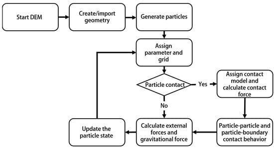
From a technological perspective, DEM can be defined as a technique that comprises finite-sized bodies having the capability of relative displacement, and therefore the contact topology and force system can be updated during the computer simulation. Modeling requires input of parameters of particles and accurate incorporation of the contact model. DEM estimates forces acting on the particles through contact mechanics and a contact detection algorithm, and thereby, acceleration, velocity, and displacement are computed using Newton’s law of motion. Different contact detection techniques are employed in algorithms to reduce the computational load. In the body-based search technique, which is a hyperlinear contact detection algorithm, each particle is considered separately for the analysis. Most DEM code follows this approach wherein the computational time increases exponentially as the number of particles in the domain increases. In contrast, with the space-based search technique, the whole domain is divided into several windows, and they are analyzed in consequence to gain computational efficiency. Assigning model parameters is a major part of modeling. Some of the particle parameters may be readily available either from the literature or direct measurements. However, in case of nonavailability, those parameters need to be obtained through calibrations. Computational time depends on the algorithm chosen for the domain, and model accuracy highly depends on the selection of proper contact model and associated parameters. A general working flow chart is shown in Figure 12.

Figure 12.
DEM modeling flow chart.
1.2. Calibration Approaches
As discussed, the determination of the appropriate contact model and model parameters in a DEM model plays a vital role in ensuring accurate representations of the physical model. DEM parameters include particle parameters and contact parameters. The selection of particle parameters is a difficult task. The selection of input parameters required for contact models makes the task more challenging. Though there is no standard procedure to calibrate DEM parameters, two approaches are commonly followed. The first method is the direct measurement approach. Although, in most cases, microscopic parameters of DEM are not measurable, attempts have been made to quantify a material’s physical parameters directly measured on a particle. Ease of measurement depends on particle scale and size [1][21]. It was found that the accuracy level of the DEM model may vary even though the input parameters have been measured accurately [2][3][22,23]. This method is generally most suitable where friction among particles is the dominant force, for example, in granular particle systems. The direct measurement approach will be accurate only if the particle size and shape are modeled accurately and if an accurate representation of physical contact behavior is ensured [4][24]. The measurement of particle microscopic parameters is arduous, if not impossible in some cases. Therefore, the second method, calibrating model parameters by measuring and matching macroscopic parameters of bulk materials, has been a more popular method among researchers.
The latter calibration approach compares the macro response of the bulk material with the measured results through an iterative procedure [5][25]. First, a laboratory experiment is typically conducted to measure material properties of interest. Then, the laboratory experiment is replicated numerically with a proper code of conduct. This does not assure alignment of the measured result with the predicted one. In such cases, critical DEM parameters need to be varied until a reasonable match between predicted and measured values is achieved, following the trial-and-error approach. It was noted that a macroscopic property can be matched with different combinations of microscopic particle parameters, which suggested that another macroscopic property should be considered as a second factor to ensure the uniqueness of calibrated parameter sets [6][26].
1.3. Implementation
Several DEM-modeling software, either proprietary or open source, are available for implementing simulations of varieties of problems dealing with particle interface. Common commercial software includes EDEM, PFC, and Rocky DEM; open-source software includes MercuryDPM, LIGGGHTS, and YADE. They are basically developed on the same principles, executing common steps of simulation including particle contact identification, implementation of contact model, and application of laws of motion and mechanics. Major differences among software include contact detection technique, user interface, post-processing capabilities, and computation performance. For example, EDEM has a three-step graphical user interface including pre-processing, simulation, and post-processing; PFC can solve the system with a combination of spheres and polyhedra having variable contact detection algorithms; Rocky DEM offers more accelerated simulation by integrating GPU cards into the computation process; and LIGGGHTS uses command line interface for pre-processing and simulation, while post-processing needs to be performed on another platform such as PARAVIEW.
2. Fundamental Studies of DEM in Soil–Plant–Machine Interactions
2.1. Contact Models
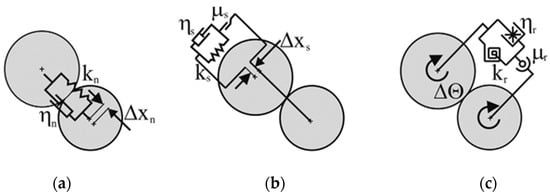
The particle–particle and particle–boundary contact models of DEM have three main components including normal force, tangential force, as well as rolling resistance models (Figure 23). Following the displacement-driven formulation suggested by Cundall and Strack [7][27] for DEM simulations, different methods for calculating normal and tangential displacements can be identified. Generally, elastic, plastic, viscous, cohesive, and adhesive interactions between neighboring particles are considered. The major difference between these interactions is the role of various forms of energy including molecular energy, kinetic energy, body energy, surface energy, boundary work, and their transformation in contact behavior. In the case of elastic contact, it is considered that energy and momentum are conserved. As for the rest of the contact types, the energy is dissipated in various ways through the contact points or affected areas between particles.

Figure 23. Schematic representation of DEM particle contact models: (a) normal (kn: normal stiffness; ηn: normal critical-damping ratio; ΔXn: overlap of two contacting spheres); (b) tangent (ks: tangential stiffness; ηs: shear critical-damping ratio; ΔXs: tangential component of relative displacement; μs: coefficient of friction); and (c) rolling (kr: rotational stiffness; ηr: rolling critical-damping ratio; Δϴ: relative rotation of two contacting particles; μr: coefficient of rolling friction) [8][28].
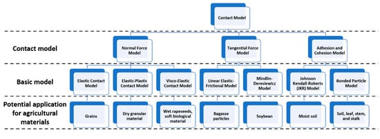
Biological materials in SPMI systems have tremendous variability in terms of properties and applications. As a result, the selection of an appropriate contact model to represent material behaviors in specific applications becomes a challenge. An attempt was made to classify common contact models being studied and used in applications of SPMI systems, as shown in Figure 34. A discussion of different contact models and their common applications is narrated in the following section to guide in determining which contact model is most suited for a specific application.

Figure 34.
Classification of contact models and their potential application for agricultural materials in DEM.
2.1.1. Normal Force Model
The elastic contact model is the most common model used to calculate normal force. The elastic contact model has two types: linear and nonlinear elastic models, where the linear elastic model represents a spring, and the nonlinear normal elastic model is commonly known as the Hertzian model [7][9][10][11][27,29,30,31]. The Hertzian model has demonstrated promising results in the simulation of compression tests and in determining the modulus of elasticity of agricultural grains [8][28]. In this approach of elastic modeling, the energy loss through contact points of particles is not taken into consideration.
The elastic–Plastic contact model contrasts with the elastic model where the plastic component introduces a plastic deformation about the contact area, thereby simulating the energy dissipation [12][32]. An adaptive model of elastic-ideal plastic behavior of particles was introduced by Thornton [13][33] and is a more advanced and realistic extension of the Hertzian elastic model. This model can be applied to dry granular material such as crop seeds with elastic behavior in the normal direction [14][34]. This model is also suitable for the contact mechanics study of soft biological material under high-impact velocity [15][35].
The visco-elastic contact model consists of a spring and a dashpot where the spring represents linear elastic behaviors, and the dashpot reflects nonlinear viscous dissipation behaviors. This model has been validated by the results of impact experiments of seeds [16][17][36,37]. This model provides the best solutions to energy dissipation mechanisms at impact velocities below the critical value for wet rapeseeds and soft biological materials such as apples and tomatoes [18][38]. This model is also found to be suitable in the case of rapeseed, which has considerable hardness [14][34].
2.1.2. Tangential Force Model
The linear elastic-frictional model, also known as the linear spring Coulomb model, combines the linear elastic spring and friction coefficient in describing static and dynamic tangential behaviors [19][39]. This model can determine tangential contact force during particle sliding as well as non sliding. This model was found to be suitable for simulating the pneumatic separation of bagasse particles [20][40].
The Mindlin–Deresiewicz model was developed based on the Mindlin–Deresiewicz contact theory, which calculates the entire past loading history, the initial state of loading, and the instantaneous relative rates of the force change for the tangential force [21][41]. Vu-Quoc and Zhang [12][32] improved and extended the theory by elaborating the tangent force-displacement model for the elastic frictional contact of particles. The model can be applied to many special and complex cases of loading histories, and it has been used for the simulation of soybean-inclined chute interaction [22][42].
2.1.3. Adhesion and Cohesion Model
The Johnson–Kendall–Roberts (JKR) model, a nonlinear model, incorporates the adhesive forces in the Hertzian contact area while considering stored elastic energy and surface energy losses [23][43]. The adhesive inter-particle forces are mainly related to the van der Waals force or electrostatic force. However, other inter-particle forces, such as liquid bridge, a result of surface tension force and capillary pressure, may also be simulated in behavior studies of the particles having a size in the range of millimeters [24][25][44,45]. The model can effectively analyze various situations of adhesion. Anand et al. [26][46] simulated particle discharge from a container with the adhesion resulting from the liquid bridge in the contact model. It is suggested that the cohesive behavior of the particles needs to be accounted for in the case of biological material with a higher level of moisture content. Therefore, this model offers a good solution in the studies of moist soil–tool interaction, plant–root interaction, and grains at high moisture levels.
Cohesive materials are often modeled using the bonded particle model (BPM), which approximates the mechanical behavior of continuum material by representing it as a cemented granular material as proposed by Potyondy and Cundall [27][47]. The bonds of finite stiffness exist at contacts to carry forces and moments. A bond can deform and will break if the threshold of force or moment exceeds the specified strength of the bond. In recent years, this model has shown its ability to simulate biological material such as soil, leaves, stems, and stalks in the applications of tillage [28][48] and harvester [29][49].
2.2. Model Parameters
DEM modeling of SPMI systems mainly involves the study of soil interaction with biological plant materials and machine components. Specifically, soil–machine, soil–plant, and plant–machine interactions are commonly considered. Model parameters are categorized as material parameters and interaction parameters [30][50]. Material parameters deal with the physical and mechanical properties of a particle such as its shape, size, density, elasticity, plasticity, shear modulus, Poisson’s ratio, and yield strength. Interaction parameters deal with the static and dynamic properties of an interaction system such as adhesion, viscous damping, and coefficients of static and rolling friction [17][31][37,51].
DEM has been successfully applied to soil–machine interactions in agriculture (e.g., [32][33][34][52,53,54]). The major challenges of using DEM involve determining the appropriate contact model and associated parameters for agricultural soils so that the model reflects the behaviors of the biological material. Model parameters of the machine component including density, shear modulus, and Poisson’s ratio of various types of metal materials such as steels, cast irons, and alloys are relatively straightforward to measure and implement in DEM simulations. There were a few studies focused on selecting appropriate contact models for agricultural soils (e.g., [35][36][37][38][55,56,57,58]). The sensitivity of model parameters on model behaviors has been studied [39][40][59,60], providing information for determining which model parameters should be calibrated. Numerous methods were used for calibrations with the direct measurement of bulk material being the most-used approach as described above. For example, Asaf et al. [41][61], Ucgul et al. [37][57], and Tamás and Bernon [42][62] simulated the cone penetration test to calibrate the soil shear modulus and soil-to-soil bond stiffness. Zhang et al. [29][49] performed the angle of repose test to calibrate soil–soil contact parameters including the coefficient of static friction and rolling friction coefficient. Similar studies have been carried out to calibrate the contact parameters in grain–grain, soil–residue, and soil–grain interactions [30][43][44][45][50,63,64,65]. Most existing models employed the contact models implemented in DEM software. These contact models may not be the best for modeling agricultural soils. For example, Sadek and Chen [39][59] used an existing contact model and found that their discrete element model underestimated soil movement resulting from a blade, possibly attributable to the contact model used. Researchers are encouraged to explore some user-defined contact models. Inappropriate contact models could be one of the reasons for discrepancies between simulations and measurements reported by many other researchers. In summary, robust contact models need to be developed, and appropriate model parameters need to be determined for successful DEM applications in SPMI system simulations.
