Your browser does not fully support modern features. Please upgrade for a smoother experience.
Submitted Successfully!
 +1 credit
Thank you for your contribution! You can also upload a video entry or images related to this topic.
For video creation, please contact our Academic Video Service.
| Version | Summary | Created by | Modification | Content Size | Created at | Operation |
|---|---|---|---|---|---|---|
| 1 | Julien Cambedouzou | -- | 5450 | 2023-08-23 10:39:23 | | | |
| 2 | Camila Xu | Meta information modification | 5450 | 2023-08-24 02:47:49 | | |
Video Upload Options
We provide professional Academic Video Service to translate complex research into visually appealing presentations. Would you like to try it?
Cite
If you have any further questions, please contact Encyclopedia Editorial Office.
Fromager, B.; Marhuenda, E.; Louis, B.; Bakalara, N.; Cambedouzou, J.; Cornu, D. Electrospinning Process of Electrospun Fibers. Encyclopedia. Available online: https://encyclopedia.pub/entry/48360 (accessed on 01 April 2026).
Fromager B, Marhuenda E, Louis B, Bakalara N, Cambedouzou J, Cornu D. Electrospinning Process of Electrospun Fibers. Encyclopedia. Available at: https://encyclopedia.pub/entry/48360. Accessed April 01, 2026.
Fromager, Bénédicte, Emilie Marhuenda, Benjamin Louis, Norbert Bakalara, Julien Cambedouzou, David Cornu. "Electrospinning Process of Electrospun Fibers" Encyclopedia, https://encyclopedia.pub/entry/48360 (accessed April 01, 2026).
Fromager, B., Marhuenda, E., Louis, B., Bakalara, N., Cambedouzou, J., & Cornu, D. (2023, August 23). Electrospinning Process of Electrospun Fibers. In Encyclopedia. https://encyclopedia.pub/entry/48360
Fromager, Bénédicte, et al. "Electrospinning Process of Electrospun Fibers." Encyclopedia. Web. 23 August, 2023.
Copy Citation
Electrospinning is a simple and versatile method to generate nanofibers. Remarkable progress has been made in the development of the electrospinning process. The production of nanofibers is affected by many parameters, which influence the final material properties. Electrospun fibers have a wide range of applications, such as energy storage devices and biomedical scaffolds.
electrospinning
single needle
multi-needle
nanofibers
parameters
1. Introduction
Fibers, in the form of continuous and elongated filaments, have been used by humans since 2700 BC with the breeding of silkworms for textile production [1]. In Australasia, silk from spiders was used for fishing, while in ancient Greece, spider webs were used as wound dressings to stop bleeding. World War II saw an increase in demand for these fibers, leading to the production of synthetic fibers derived from petroleum, sometimes with better chemical or physical properties than silk, depending on the polymer [2][3]. Nylon fibers, first introduced by DuPont, immediately caught the public’s attention. In 2018, more than 50 million tons of synthetic fibers were produced, with a predominance of polyester filaments. Therefore, many different types of synthetic polymers originating from crude oil, such as polystyrene and polyacrylonitrile (PAN), and natural biopolymers, such as chitosan and polylactic acid, have been developed one after the other for various industries. Compared to synthetic fibers, natural fibers have many advantages thanks to their abundance, availability, and low cost, explaining why the global demand for synthetic fibers has been largely reduced, with synthetic fibers having been replaced by natural biofibers [4]. Nowadays, within the domain of fiber technology, nanofiber mats have a broad range of applications, especially in areas of engineering and science. These include optical and chemical sensors, nanocatalysis, and energy storage [5][6][7], as well as applications in defense, aerospace, transportation, and protective clothing industries [6]. They are also used in air and water filters or for drug delivery for medical and biotechnological purposes [8]. To produce nanofibers, different methods have been developed, such as wet, dry, melt, and gel spinning. During these processes, polymer jets are formed under external mechanical drawing/shearing forces when passing through spinnerets, and fibers are formed due to the solidification of the jets because of drying or precipitation. However, jets are only stretched to a limited extent, corresponding to the formation of fibers with diameters ranging from 10 to 100 μm [9]. However, even with further mechanical drawing after solidification, the resulting fibers still cannot reach the nanoscale. In 1902, a novel technique similar to electrospraying was created, allowing fibers to be created at the nanoscale; this technique is known as electrospinning [10]. Both techniques rely on a high voltage to eject liquid jets, with the major difference being the viscosity and viscoelasticity of the liquid involved and, thus, the behavior of the jet [11]. Electrospinning is a simple and low-cost method to prepare fibers at the nanoscale with an electric field. This method produces non-woven nanofiber mats, where the fiber diameter ranges from ten to a hundred nanometers. Extraordinary properties, such as small diameters or large specific surface areas, can be obtained thanks to this technique. Also, a wide selection of polymers can be electrospun from diverse solvents, including aqueous solutions, making the spinning process itself environmentally friendly. Mostly toxic or corrosive solvents are used for waterproof polymers, while only some can also be electrospun from a low-toxicity solvent such as dimethyl sulfoxide (DMSO) [12][13][14]. The classic electrospinning process uses one needle to draw the polymeric solution out and form fibers. However, this method is very time-consuming, limiting the potential scale-up application of the electrospun nanofibers. Many multi-jet [15] and multi-needle [16] electrospinning methods have been investigated to overcome the productivity problem, increasing the flow rate of the solution. However, the generation of multiple jets creates other problems, such as jet repulsion and lower process controllability [17]. Polyacrylonitrile (PAN) is a synthetic polymer widely used in electrospinning due to its high tensile strength, thermal stability, carbon yield, and chemical resistivity. Electrospun PAN nanofibrous membranes have received particular interest due to their appealing properties, including small fiber diameters, as well as capabilities to control pore sizes among nanofibers and to incorporate molecules, cells, or proteins [14][18][19]. PAN is the primary precursor to prepare high-performance carbon fibers: almost 90% of the carbon nanofibers in the world are produced from PAN-based precursors [20]. Three main processes are involved in carbon fiber preparation: the spinning of PAN precursor, thermal–oxidative stabilization (ToS), and carbonization [21]. Stabilization is a complex, exothermic process and the most important step that influences the properties of the final fibers. During this step, the linear polymer transforms itself into a cyclic-structured polymer, also called a ladder-like structure. Thermal stabilization proceeds mainly at a specific temperature, ranging from 200 to 300 °C, for 1–2 h in the air [22]. Oxygen plays an important role in the physical and chemical structural changes that occur during ToS. It is recognized that oxygen not only affects the oxidative and crosslinking reactions but also makes the cyclization and dehydrogenation reactions (which occur simultaneously during the thermal stabilization process) easier. In addition, the exact reaction mechanism varies depending on the gas atmosphere, heating rate, copolymer used, etc. [23][24]. Thus, having a better understanding of the structural evolution of PAN fibers during stabilization is a major issue in predicting the final structure of the polymer and, therefore, in functionalizing it.
2. Electrospinning Process
2.1. Principle
The simplest form of electrospinning is the single-needle configuration, which has been investigated and reviewed by many researchers [6][9][18][25][26][27]. The simulation of the electric field and modeling of the electrospinning process were also carried out in an effort to provide a better understanding of this approach [28]. Only a few components are required: a syringe containing a polymeric solution, a metallic needle, a high-voltage power supply, and a metallic collector (with variable morphology). The power supply can be either a direct current (DC) or, more rarely, an alternating current (AC) [25]. As illustrated in Figure 1, the basic setup for electrospinning is rather simple, making it accessible to as many researchers as possible.

Figure 1. Schematic diagram of processing steps for the fabrication of nanofibers. The polymeric solution is composed of the solvent, the polymer, and, in some cases, additives such as nanoparticles or carbon nanotubes.
Free charges carried by the liquid interact with the applied electric field. Tensile-force-inducing fiber jetting occurs due to the potential difference between the charged liquid in the spinneret and the grounded collector. Usually, electrospinning unfolds in four steps (Figure 2): (i) the liquid droplet is charged, and the Taylor cone is formed; (ii) the charged jet is extended in a straight line; (iii) the jet is thinned in the presence of an electric field, and electrical bending instability appears and increases; (iv) finally, the solid jet fibers are collected by a grounded collector [17][25].
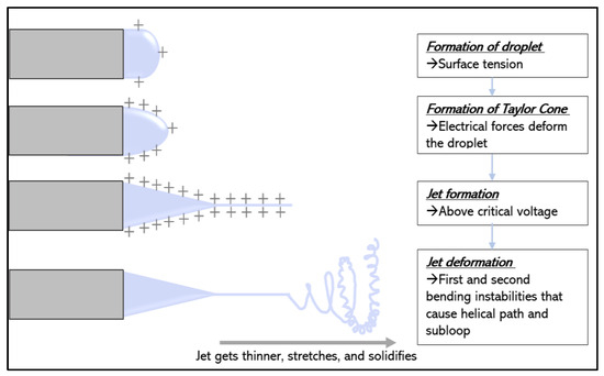
Figure 2. The different steps of the electrospinning process. The ‘+’ illustrate the charges at the surface of the droplet. A droplet is created due to the syringe pump. The surface area of the droplet increases to decrease the electric repulsion. A jet is ejected from the nozzle, and binding instabilities lead to the stretching and thinning of the jet. Finally, the solvent is evaporated, and the fibers are collected by a metallic collector. Inspired by reference [17].
2.2. Formation of Taylor Cone upon Charging a Liquid Droplet
A syringe with a needle is commonly used as the spinneret to feed the solution at a controlled rate using a syringe pump. When there is a potential difference (ranging from 10 to 30 kV) between the spinneret and the collector, negative and positive charges will be separated within the liquid; the charges with the same polarity as the spinneret will migrate toward the droplet’s surface, leading to excess charges. By increasing the voltage, more charges will accumulate at the liquid surface. This increase in the density of surface charges tends to deform the shape of the droplet, leading to an increase in surface area to attenuate the electric repulsion [29], as illustrated in Figure 2.
2.3. Stretching and Thinning of the Charged Jet
At the same time, the reciprocal repulsion of charges produces a force that opposes the surface tension, and ultimately, the polymer solution flows in the direction of the electric field. A further increase in the electric field causes the spherical droplet to deform and assume a conical shape, which is called the Taylor cone. At the same stage, ultrafine fibers emerge from the conical polymer droplet at high speed, accelerated by the electric field. The jet is extended in the direction of the electric field, and then it is collected by the metallic collector kept at an optimized distance [9].
The jet formed initially travels in a straight path due to surface tension and viscoelastic forces, which tend to prevent the jet from moving in other directions. Both the acceleration and the diameter of the jet decrease as the jet is continuously stretched. Solvent evaporation and a jet diameter reduction lead to an increase in the surface charge density of the fiber, which results in increasing repulsive forces in the jet. When the acceleration of the jet is too low, bending instabilities appear [9] and are described as long-wave perturbations to the jet, driven by a lateral electrostatic force in the radial direction relative to the jet, resulting from the electrostatic repulsion among surface charges [29][30].
The mechanism for the binding instability can be explained using Earnshaw’s theorem, illustrated in Figure 3. It states that a charge cannot maintain a stable equilibrium condition by relying only on the interaction between charges. If three adjacent points of equal charges in a straight jet are considered, the forces F and F′ acting on the middle charge are of equal magnitude and in opposite directions following the equation:

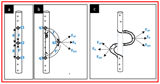
Figure 3. Representation of binding instabilities, also called whipping instability, illustrating Earnshaw’s theorem. (a) First, the jet propagates in a straight line, highly accelerated due to the electric field. (b) As the acceleration and the fiber diameter decrease, the surface charge density increases, leading to an increase in repulsive forces F and F′. A perturbation (represented by dotted lines) begins to grow in response to the repulsive electric forces. The charges carried by the perturbed segment are forced (FDO) downward and outward by the charges above and below the perturbed region, while this perturbed segment is forced (FUO) upward and outward by the charges below the perturbation. The resultant force (FR) is perpendicular to the straight jet and grows exponentially with time. At the same time, the repulsion of adjacent charges moves with the jet, propagating and amplifying the phenomenon. (c) The elongation of the fibers increases more rapidly in the curved segment, creating nanofibers. Inspired by reference [29].
In the straight segment, the flow direction, i.e., the trajectory of a segment of the jet, is parallel to the axis of the jet. When a small perturbation causes the movement of the middle charge out of the straight line, the bending perturbation begins. An angle, θ, is created, resulting in a lateral force FR that leads to the initiation of jet instability given by:

This perturbation grows rapidly under the influence of the charge carried with the jet. It leads to elongation, reducing the diameter of the jet. After the first bending instability, the jet is subjected to subsequent higher-order bending instabilities, leading to the formation of subloops. These loops significantly contribute to the thinning of the jet for the formation of the nanofibers. A succession of three bending instabilities with decreasing diameter is often observed before the jet solidifies, as shown in Figure 4 [17][25].
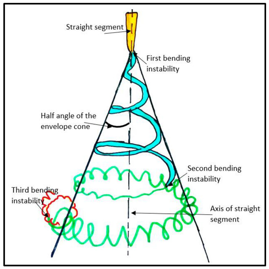
Figure 4. The typical path of an electrospun jet. It starts with a straight segment (in yellow), followed by a coil with decreasing diameter (first binding coil in blue). After several turns are formed, a new electrical instability forms a smaller coil in a turn of the larger coil (second bending instability in green). The turns of the smaller coil transform into an even smaller coil (third bending instability in red). Usually, the solidification of the thin jet helps to stop elongation. Inspired by reference [29].
2.4. Deposition of Solid Fibers
While the jet stretches and becomes thinner as it travels further under the influence of electrostatic forces, it undergoes solidification due to solvent evaporation. After solidification, some can find charges still trapped on the surfaces of the dry fibers, but all instabilities will stop [25].
In general, a grounded collector is used to collect fibers. The morphology of fibers is mainly determined by the whipping instability. After deposition, most charges will be dissipated through the grounded collector. However, due to the low conductivity of most materials used to produce fibers, a residual number of charges can still be found on the surfaces of the collected fibers [31]. Different collectors can be employed to obtain various alignments of fibers. The simplest and most common collector is a flat plate of alumina, leading to a non-woven fibrous mat. Different geometries can be obtained using different shapes, such as rotating drums or parallel electrodes, to obtain aligned fibers. In this case, the optimization of the rotating speed and voltage applied needs to be carried out [17].
2.5. Control of the Electrospinning Process
The formation of electrospun nanofibers is determined by the processing parameters, including the voltage applied, the flow rate of the polymeric solution, the distance between the syringe tip and the collector, and the diameter of the needle (Table 1). Other parameters, such as environmental parameters as well as solution parameters, also play a significant role in the fabrication of nanofibers.
Table 1. Summary of the parameters impacting the electrospinning process.
| Voltage | Flowrate | Distance between Collector and Needle | Needle Diameter | Polymer Concentration | Solution Conductivity | Solvent | Speed Rotation and Morphology of Collector | |
|---|---|---|---|---|---|---|---|---|
| Range | 10–30 kV | 0.1–4.5 mL/h | 5–20 cm | 0.2–1.5 mm | ||||
| Impact | ↗voltage ↘fibre diameter |
↗needle diameter ↗fibre diameter |
↗concentration ↘fibre diameter |
↗conductivity ↘fibre diameter |
Impact the morphology of fibres and pores size and alignment | |||
| Note | Above critical voltage, formation of beads | Above critical flowrate, formation of beads | Above and under critical distance, formation of beads | (1) Under critical diameter, formation of clogging (2) Above it, solidification before jet eject |
Too low leads to formation of beads | (1) Needs to dissolve completely the polymer (2) Evaporation rate neither too low nor too high |
2.5.1. Effects of the Voltage
It can be seen above that a high voltage applied to a solution in a metallic needle will induce the deformation of a spherical droplet into a Taylor cone and the formation of nanofibers when reaching a critical voltage. The latter depends on the polymer used, and it ranges from 10 to 30 kV. It is accepted that the higher the voltage, the smaller the diameter of the fibers due to the correlation between the charge repulsion within the polymer jet and the stretching of the polymer [32]. Nevertheless, Son et al. reported that an increase in the voltage applied beyond the critical voltage will result in the formation of beads or beaded nanofibers [33].
2.5.2. Effects of the Flow Rate
Higher flow rates will undoubtedly increase the production rate of the electrospinning process but can have negative effects on the morphology of the fibers if not properly controlled. Uniform nanofibers can be prepared via an optimal flow rate for a mixture. Flow rates generally range from 0.1 to 4.5 mL/h, depending on the polymer used [17]. When the flow rate is above this critical value, the formation of beads occurs, which is due to incomplete drying of the nanofiber jet during its flight between the needle tip and the metallic collector and a decrease in the surface charge density [26].
2.5.3. Effect of the Distance between Metallic Collector and Needle
The distance between the nozzle tip and the collector is an important parameter in producing excellent-quality nanofibers. The nanofiber morphology can be easily affected by the distance (usually ranging from 5 cm to 20 cm [34]) because it depends on the evaporation rate and the binding instabilities of the polymeric solution. A minimum distance is required to allow sufficient time to complete solvent evaporation to prevent defects like beaded or flattened fibers. Too small a collector–needle distance results in a small circular area with a deep color called a “wet spot”, which can be found in the center of the mat [35]. Like the applied voltage and the flow rate, this minimum distance also varies with the polymer system. However, Zhang et al. observed no significant changes in polyvinyl alcohol (PVA) fiber morphology when varying the needle–collector distance from 8 to 15 cm [36].
2.5.4. Effects of Needle Diameter
Stainless steel needles are the most widely used nozzles in electrospinning, with a typical inner diameter ranging from 0.2 to 1.5 mm. Generally, a large needle diameter will lead to a large fiber diameter. The increase in the fiber diameter results from the fact that with a larger tip, a larger droplet is formed, and thus, a longer length of the straight jet is obtained, which in turn reduces the whipping jet motion. Clogging of the tip can also occur when the needle diameter is too small and the solution is too viscous; when the needle diameter is too large, the solution tends to solidify with increased exposure to air [26].
2.5.5. Effects of Polymer Concentration in Solution
The electrospinning process relies on the phenomenon of the uniaxial stretching of the charged jet. The jet depends on the arrangement of the polymer particles in the solution, which is a direct consequence of the solution concentration. For example, when the concentration of the polymer is too low, the entanglement of polymeric chains is limited, breaking fibers into fragments and leading to beaded fibers. Increasing the concentration will increase the viscosity, which increases the chains’ entanglement among the polymer chains. This overcomes the surface tension and results in the formation of defect-free fibers [25]. The molecular weight of the polymer also plays a key role. Jacobs et al., using poly (ethylene oxide) (PEO) with two different molecular weights (300,000 and 900,000 g/mol), reported that smooth fibers are formed at 6 wt% with a higher molecular weight, while a higher concentration is required for solutions with a lower molecular weight [37].
2.5.6. Effect of Solution Conductivity
Solution conductivity affects both Taylor cone formation and fiber diameter. For a low-conductivity solution, the surface of the droplet has no charge to form a Taylor cone, and then the electrospinning process cannot take place. Increasing the conductivity with the addition of surfactants or salt will increase the charges on the surface of the droplet, leading to the formation of a Taylor cone and a decrease in the fiber diameter. Several types of salts have been used in various amounts (generally up to 2%). Above 2%, the jet becomes unstable, which inhibits the electrospinning process [26]. Son et al. studied the effects of poly (allylamine hydrochloride salts) (PAH) and poly (acrylic acid sodium salt) (PAA) on PEO nanofibers. By adding only 0.1% of each salt (PAH and PAA), the diameter of PEO fibers was reduced by 55%, from 360 nm to 200 nm [33]. This shows that adding a surfactant and salt increases the conductivity of the solution, and the increased electric field force improves the binding instabilities of the jet, which promotes the stretching and thinning of the nanofibers.
2.5.7. Solvent Effects
The selection of the solvent is one key parameter for the formation of homogeneous, smooth, and beadless electrospun nanofibers. First, the polymer needs to be completely soluble in this solvent, as a homogeneous solution is essential for the electrospinning process. However, a solvent with a high-solubility parameter does not necessarily produce a solution suitable for electrospinning [33]. Secondly, the solvent should have a moderate boiling point, which determines the evaporation rate and, thus, the solidification rate of the jet. Extremely high volatility is not desirable because the jet may solidify immediately at the needle tip, blocking the spinneret and stopping the electrospinning process. If the volatility is too low, the fibers will still be wet when they are deposited in the collector, which can lead to the formation of beaded nanofibers [26].
The dielectric constant also plays a significant role because it controls the magnitude of electrostatic repulsion among the surface charges residing in the jet. Increasing the dielectric constant implies increasing the applied voltage to achieve a stable jet. Therefore, water is not a favorable solvent for electrospinning due to its high dielectric constant and, thus, the attenuation of electrostatic repulsion. The commonly used solvents in electrospinning are alcohol, dichloromethane, chloroform, dimethylformamide (DMF), tetrahydrofuran (THF), acetone, dimethyl sulfoxide (DMSO), hexafluoroisopropanol (HFIP), and trifluoroethanol. In some cases, it can be interesting to mix two solvents to achieve an optimal formulation for electrospinning [25]. Nevertheless, the use of two solvents will have an impact on the fiber’s porosity: the different evaporation rates of the solvents will lead to phase separation and hence will result in the fabrication of a porous material [26].
2.5.8. Effect of the Targeted Drum Size and Its Speed of Rotation
The morphology of the fibers is influenced by the nature of the collector. The choice of the collector type will be guided by the desired area of the fibers (a drum collector will give a higher area of aligned fibers than a disc collector, for example). To obtain aligned fibers, a rotating collector, an array of electrodes, or a pair of magnets is required. When the collector is an array of electrodes, the alignment will be tuned by acting on the electric field, whereas alignment will be controlled by the magnetic field when the collector is a pair of magnets. By modifying the rotation speed of a rotator collector, it is the mechanical stretching forces that will influence the alignment of fibers [26][38]. Usually, when the rotation speed is under 1000 rpm, the mesh is randomly organized. Above 500 rpm, the higher the speed is, the better the alignment is because polymer molecular chains will be more aligned according to the fiber axis, and so the crystal orientation of the fibers will be improved [39][40]. For example, the impact of rotation speed was studied for POM (polyoxymethylene) nanofibers, with POM being a highly crystalline polymer. It has been shown that the morphology of the nanofibers changes from a folded chain crystal to an extended chain crystal when the rotation speed of the drum collector increases. [41] In another study, four speeds were tested (500, 1000, 1500, and 2150 rpm) to obtain electrospun nanofibers of PVA. For 500 and 1000 rpm, Andreas et al. obtained a random orientation, while for 1500 and 2150 rpm, the orientation was more organized [42].
2.6. Multiple Needles for Large-Scale Production
One major challenge that electrospinning is facing nowadays is upscaling in response to industry demand. In most published work about electrospinning, authors have used an experimental laboratory setup using a single syringe, as described above, with an inner diameter of 0.2 to 1.5 mm. Depending on the polymeric solution, the flow rate is typically limited to 5 mL per hour. Consequently, nanofibers are obtained at a very low yield, which limits the industrial applications of electrospinning.
The most important parameter for high efficiency in the electrospinning process is the flow rate. However, the flow rate is largely determined by the strength of the electric field. Increasing the flow rate means increasing the voltage, which will lead to the formation of droplets instead of fibers (see Control of the Electrospinning Process, Effects of the Voltage) and an increase in the nanofiber diameter (see Control of the Electrospinning Process, Effects of the Flow Rate). Therefore, it is not feasible to substantially increase the throughput of the single-needle electrospinning process when a compromise must be made between the applied voltage and the flow rate.
Some have tried to use needleless electrospinning to increase production. However, some parameters, such as solvent evaporation, are easily variable, which makes it difficult to obtain accurate and reproducible fabrication in industry-scale production.
To overcome the imperfections of single-needle and needleless electrospinning, multi-needle electrospinning can be an important choice for nanofiber production. The combination of several individual needles as the spinneret of the electrospinning setup is the most direct method to increase productivity. This method is also useful for producing composite fibers of two or more polymers when there is no common solvent.
2.6.1. Multi-Needle Electrospinning Process
-
Principle and Properties
The working mechanism of a multi-needle electrospinning process is very close to that of the conventional single-needle electrospinning process. For a single jet emitted from a single needle, the initial straight path of the jet is driven by forces in the direction of the electric field. For the multi-nozzle setup, multiple jets can be simultaneously ejected from the needles, and all of them then undergo bending instability. The jets are influenced by Coulombic forces Fc exerted by the jets’ neighbors, in addition to the electric field force Fe. The deviation of the jet is the result of these two forces, as shown in Figure 5 [17][43].
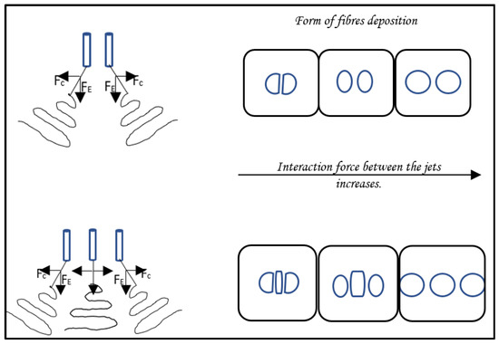
Figure 5. Force analysis in multiple-nozzle electrospinning with typical fiber deposition shapes. In the three-nozzle configuration, the path of the central jet develops in the same way as that in single-jet electrospinning due to the symmetrical arrangement of the side jets, while the paths of the outer jets deviate because of Coulomb forces. In addition to the electric field force FE, Coulomb forces FC are exerted on each jet by their neighbors. The higher the voltage, the further away the patterns will be. Inspired by reference [17].
In the multi-needle electrospinning setup, the inter-nozzle distance is usually set at 10–50 mm, which causes complex effects in the electrospinning process. When the distances between needles are relatively small, the mutual interferences of the electric fields at the tips will be larger, which may cause an uneven electric field, which directly affects fiber quality [27].
Many factors affect the electric field, including the needle configuration, needle number, and needle spacing. The spacing is mainly affected by the diameter of the needles and the properties of the polymeric solution. As shown in Figure 5, increasing the inter-needle distance decreases the repulsion among jets while pushing the jets closer, resulting in the concentration of the fibers created. The number of needles arranged over a certain area is dependent on both the spacing and the layout, and it ultimately determines the throughput of fiber production. The layout of the array controls the distribution of the electric field to obtain the most uniform electric field possible among the jets [25]. The configuration of multiple needles can be divided into two types: linear arrays, by organizing needles in a straight line [28], and two-dimensional arrays, by placing needles in a special layout, including squared [38], circular elliptic [39], hexagonal [43], and triangular patterns.
Several examples of multiple needles in a linear array, the simplest arrangement, have been reported. For instance, a linear multi-needle electrospinning setup with four needles has been designed to produce nanofiber webs.
Zhu et al. showed that the charge density distribution of the needles and the morphology of the jet vary, depending on the number and the placement of nozzles used in space. For a single needle, the charge distribution is uniform and mainly distributed at the end of the tip. Contrarily, in the double-needle layout, when a needle is added next to another one, they share the same voltage, and the same charges will repel each other. Then, an uneven charge density distribution appears, where the charge density outside the tips is higher than that on the adjacent part of the two-needle tip. In the three-needle electrospinning process, the electric field at the middle tip is affected by the electric field on both sides, and this phenomenon results in a uniform charge distribution in the middle tip and a non-uniform charge distribution in the two other needles. Experimental and simulated results showed that the behavior of border jets along the linear array was different from that of the central jet, such as the bending direction and envelope cone. However, every jet in both linear configurations was subject to a characteristic bending instability similar to that in single-jet electrospinning [38].
In addition, the outer jets have longer initial straight regions and larger envelope cones than the central jet due to the progressive weakening of the electrical field from the edge to the center. It is observed that increasing the voltage also increases the straight lengths and the envelope cones of the central jet and the outer jet, as well as the deviation angle of the outer jet. However, if the voltage is too low, the electric force is not strong enough, and the jet cannot eject from the central needle [43].
Most investigations on multi-needle electrospinning have been focused on processes with two-dimensional needle arrays. For example, multi-needle spinning with elliptic and circular arrangements was designed to improve the process stability and production efficiency [39]. Yang et al. used a hexagonal array composed of seven needles, with one needle located in the center. They found that the needle at the center behaved as in the normal electrospinning process, while the jet from the peripheral nozzle was directed outward due to repulsive electric forces [40]. A complex design has been created by Theron et al. with a 3 × 3 needle matrix, and they succeeded in reaching 22.5 L·cm−1 min−1 due to their nine-needle electrospinning preprocess. Moreover, stable and uniform fibers have been obtained [41].
-
Control of fiber formation in multi-needle electrospinning setup.
Several disadvantages of the multi-nozzle system include repulsion by adjacent jets and the non-uniform electrical field at each nozzle tip of the spinneret. Repulsion at the jets leads to difficulties in the collection, while a non-uniform electric field results in processing problems. Some research on electric fields has already been conducted, like the work of Chan et al., which considers the effect of linear-array nozzle configurations (the angle between the nozzles) on the electric field distribution, to solve this problem. Three angles were tested: 180°, 100°, and 90°. Simulations and experiments showed that decreasing the angle between the nozzles increased the electric field strength, and it is well known that increasing the electric field will lead to a decrease in fiber diameter. Therefore, fibers electrospun with an angle of 90° will have a smaller diameter (about 25% reduction) than fibers electrospun with an angle of 180° [28].
In the case of many needles, a decrease in needle spacing increases the deposition rate over a small area. However, it leads to an increase in electric repulsion between jets. Therefore, controlling the distribution and the electromagnetic field in the working space is essential. Both can be manipulated using auxiliary electrodes. In single-needle electrospinning, auxiliary electrodes are used to produce multiple jets [15]. Auxiliary electrodes (also called secondary electrodes) with the same polarity as the needle tend to concentrate the electric field, reducing or neutralizing the repulsion among the jets. Different auxiliary electrode shapes (Figure 6) have been tested to try to control the jets. A hexagonal array (Figure 6A) within a cylindrical auxiliary electrode [17] tends to reduce electric field interferences and stabilize the jet motion. Thicker fibers were obtained due to the secondary electrode, which interferes with the jet and thus the bending instabilities, leading to a decrease in fiber stretching. Contrary to this configuration, an auxiliary ring electrode (Figure 6B) [42] provides a more uniform electric field near the nozzle tips and greater mean electric field strength in the space between the nozzles and the collector. This leads to thinner and more uniform fibers. As depicted in Figure 6C, a flat plate [17] was used as a secondary electrode. By adjusting the position of the flat plate, smaller fiber diameters and more concentrated fibers were observed when the electrode was aligned at the edge of the needle, resembling a flat spinneret with holes.
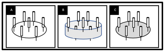
Figure 6. Different types of auxiliary electrodes in multiple-nozzle electrospinning: (A) ring electrode, (B) cylindrical electrode, and (C) plate electrode. Inspired by reference [17].
2.6.2. Other Approaches
Some other strategies have been explored [44]. First, some nozzle technologies apply a critical value, inducing the formation of simultaneous multiple jets. For this method, two spinnerets can be used, namely, either a rotating spinneret, which induces the mechanical rotation of the solution, or a stationary spinneret, which needs an auxiliary force such as a magnetic field. Then, alternating-current electrospinning has been shown to increase the production of nanofibers six-fold. Another method is ultrasound-enhanced electrospinning. It was used to produce PAN nanofibers with an improved production rate.
2.6.3. New Directions for Future Development
Despite many reports on the successful demonstration of electrospinning as a reproducible and versatile method, the main issue is the large amount of solvent used, resulting in both economic and environmental concerns. The solvent represents about 80 to 90% of the solutions involved in traditional electrospinning. During the process, the solvent is lost while the fibers are stretched, and it is generally not collected or recycled. Finally, there is a critical demand to develop an electrospinning process based on “green” solvents or even solvent-free systems.
In general, single-needle electrospinning is only suitable for laboratory use, as it suffers from low productivity. To solve this issue, innovative modifications to the conventional electrospinning setup have been made, including a multi-needle electrospinning process. However, for this process, future efforts should be concentrated on solving the problems related to undesirable interactions, leading to the generation of inhomogeneous fibers or poor fiber distribution in the collected mat.
References
- Cherry, R.H. History of Sericulture. Bull. Entomol. Soc. Am. 1987, 33, 83–85.
- Vollrath, F.; Knight, D.P. Liquid Crystalline Spinning of Spider Silk. Nature 2001, 410, 541–548.
- Heim, M.; Keerl, D.; Scheibel, T. Spider Silk: From Soluble Protein to Extraordinary Fiber. Angew. Chem. Int. Ed. 2009, 48, 3584–3596.
- Thyavihalli Girijappa, Y.G.; Mavinkere Rangappa, S.; Parameswaranpillai, J.; Siengchin, S. Natural Fibers as Sustainable and Renewable Resource for Development of Eco-Friendly Composites: A Comprehensive Review. Front. Mater. 2019, 6, 226.
- Thenmozhi, S.; Dharmaraj, N.; Kadirvelu, K.; Kim, H.Y. Electrospun Nanofibers: New Generation Materials for Advanced Applications. Mater. Sci. Eng. B 2017, 217, 36–48.
- Ramakrishna, S.; Fujihara, K.; Teo, W.-E.; Yong, T.; Ma, Z.; Ramaseshan, R. Electrospun Nanofibers: Solving Global Issues. Mater. Today 2006, 9, 40–50.
- Liu, Q.; Zhu, J.; Zhang, L.; Qiu, Y. Recent Advances in Energy Materials by Electrospinning. Renew. Sustain. Energy Rev. 2018, 81, 1825–1858.
- Hu, X.; Liu, S.; Zhou, G.; Huang, Y.; Xie, Z.; Jing, X. Electrospinning of Polymeric Nanofibers for Drug Delivery Applications. J. Control. Release 2014, 185, 12–21.
- Luo, C.J.; Stoyanov, S.D.; Stride, E.; Pelan, E.; Edirisinghe, M. Electrospinning versus Fibre Production Methods: From Specifics to Technological Convergence. Chem. Soc. Rev. 2012, 41, 4708.
- Cooley, J.F. Apparatus for Electrically Dispersing Fluids. U.S. Patent 692,631, 4 February 1902.
- Von Bailey, A.G. Electrostatic Spraying of Liquids. Research Studies Press LTD: Taunton, Somerset/John Wiley & Sons Inc, New York 1988; 197 Seiten, 24,75$. Phys. Unserer Zeit. 1989, 20, 160.
- Sirelkhatim, N.; LaJeunesse, D.; Kelkar, A.D.; Zhang, L. Antifungal Activity of Amidoxime Surface Functionalized Electrospun Polyacrylonitrile Nanofibers. Mater. Lett. 2015, 141, 217–220.
- Wehlage, D.; Blattner, H.; Mamun, A.; Kutzli, I.; Diestelhorst, E.; Rattenholl, A.; Gudermann, F.; Lütkemeyer, D.; Ehrmann, A. Cell Growth on Electrospun Nanofiber Mats from Polyacrylonitrile (PAN) Blends. AIMS Bioeng. 2020, 7, 43–54.
- Sabantina, L.; Kinzel, F.; Hauser, T.; Többer, A.; Klöcker, M.; Döpke, C.; Böttjer, R.; Wehlage, D.; Rattenholl, A.; Ehrmann, A. Comparative Study of Pleurotus Ostreatus Mushroom Grown on Modified PAN Nanofiber Mats. Nanomaterials 2019, 9, 475.
- Liu, Y.; Zhang, L.; Sun, X.-F.; Liu, J.; Fan, J.; Huang, D.-W. Multi-Jet Electrospinning via Auxiliary Electrode. Mater. Lett. 2015, 141, 153–156.
- Yan, T.; Tian, L.; Pan, Z. Structures and Mechanical Properties of Plied and Twisted Polyacrylonitrile Nanofiber Yarns Fabricated by a Multi-Needle Electrospinning Device. Fibers Polym. 2016, 17, 1627–1633.
- SalehHudin, H.S.; Mohamad, E.N.; Mahadi, W.N.L.; Muhammad Afifi, A. Multiple-Jet Electrospinning Methods for Nanofiber Processing: A Review. Mater. Manuf. Process. 2018, 33, 479–498.
- Gao, H.; Yang, Y.; Akampumuza, O.; Hou, J.; Zhang, H.; Qin, X. A Low Filtration Resistance Three-Dimensional Composite Membrane Fabricated via Free Surface Electrospinning for Effective PM2.5 Capture. Environ. Sci. Nano 2017, 4, 864–875.
- Marhuenda, E.; Fabre, C.; Zhang, C.; Martin-Fernandez, M.; Iskratsch, T.; Saleh, A.; Bauchet, L.; Cambedouzou, J.; Hugnot, J.-P.; Duffau, H.; et al. Glioma Stem Cells Invasive Phenotype at Optimal Stiffness Is Driven by MGAT5 Dependent Mechanosensing. J. Exp. Clin. Cancer Res. 2021, 40, 139.
- Yusof, N.; Ismail, A.F. Post Spinning and Pyrolysis Processes of Polyacrylonitrile (PAN)-Based Carbon Fiber and Activated Carbon Fiber: A Review. J. Anal. Appl. Pyrolysis 2012, 93, 1–13.
- Hameed, N.; Sharp, J.; Nunna, S.; Creighton, C.; Magniez, K.; Jyotishkumar, P.; Salim, N.V.; Fox, B. Structural Transformation of Polyacrylonitrile Fibers during Stabilization and Low Temperature Carbonization. Polym. Degrad. Stab. 2016, 128, 39–45.
- Chen, L.; Shen, Z.; Liu, J.; Liang, J.; Wang, X. Effects of Oxygen on the Structural Evolution of Polyacrylonitrile Fibers during Rapid Thermal Treatment. RSC Adv. 2020, 10, 6356–6361.
- Park, D.U.; Han, N.K.; Ryu, J.H.; Park, W.H.; Jeong, Y.G. Spectroscopic Analyses on Chain Structure and Thermal Stabilization Behavior of Acrylonitrile/Methyl Acrylate/Itaconic Acid-Based Copolymers Synthesized by Aqueous Suspension Polymerization. Fibers Polym. 2018, 19, 2007–2015.
- Dang, W.; Liu, J.; Wang, X.; Yan, K.; Zhang, A.; Yang, J.; Chen, L.; Liang, J. Structural Transformation of Polyacrylonitrile (PAN) Fibers during Rapid Thermal Pretreatment in Nitrogen Atmosphere. Polymers 2020, 12, 63.
- Xue, J.; Wu, T.; Dai, Y.; Xia, Y. Electrospinning and Electrospun Nanofibers: Methods, Materials, and Applications. Chem. Rev. 2019, 119, 5298–5415.
- Haider, A.; Haider, S.; Kang, I.-K. A Comprehensive Review Summarizing the Effect of Electrospinning Parameters and Potential Applications of Nanofibers in Biomedical and Biotechnology. Arab. J. Chem. 2018, 11, 1165–1188.
- Zhou, F.-L.; Gong, R.-H.; Porat, I. Mass Production of Nanofibre Assemblies by Electrostatic Spinning. Polym. Int. 2009, 58, 331–342.
- Park, C.H.; Pant, H.R.; Kim, C.S. Novel Robot-Assisted Angled Multi-Nozzle Electrospinning Set-Up: Computer Simulation with Experimental Observation of Electric Field and Fiber Morphology. Text. Res. J. 2014, 84, 1044–1058.
- Reneker, D.H.; Yarin, A.L. Electrospinning Jets and Polymer Nanofibers. Polymer 2008, 49, 2387–2425.
- He, J.-H.; Wu, Y.; Zuo, W.-W. Critical Length of Straight Jet in Electrospinning. Polymer 2005, 46, 12637–12640.
- Collins, G.; Federici, J.; Imura, Y.; Catalani, L.H. Charge Generation, Charge Transport, and Residual Charge in the Electrospinning of Polymers: A Review of Issues and Complications. J. Appl. Phys. 2012, 111, 044701.
- Song, Z.; Chiang, S.W.; Chu, X.; Du, H.; Li, J.; Gan, L.; Xu, C.; Yao, Y.; He, Y.; Li, B.; et al. Effects of Solvent on Structures and Properties of Electrospun Poly(Ethylene Oxide) Nanofibers: ARTICLE. J. Appl. Polym. Sci. 2018, 135, 45787.
- Son, W.K.; Youk, J.H.; Lee, T.S.; Park, W.H. The Effects of Solution Properties and Polyelectrolyte on Electrospinning of Ultrafine Poly(Ethylene Oxide) Fibers. Polymer 2004, 45, 2959–2966.
- Hekmati, A.H.; Rashidi, A.; Ghazisaeidi, R.; Drean, J.-Y. Effect of Needle Length, Electrospinning Distance, and Solution Concentration on Morphological Properties of Polyamide-6 Electrospun Nanowebs. Text. Res. J. 2013, 83, 1452–1466.
- Xiao, S.; Shen, M.; Ma, H.; Guo, R.; Zhu, M.; Wang, S.; Shi, X. Fabrication of Water-Stable Electrospun Polyacrylic Acid-Based Nanofibrous Mats for Removal of Copper (II) Ions in Aqueous Solution. J. Appl. Polym. Sci. 2010, 116, 2409–2417.
- Zhang, C.; Yuan, X.; Wu, L.; Han, Y.; Sheng, J. Study on Morphology of Electrospun Poly(Vinyl Alcohol) Mats. Eur. Polym. J. 2005, 41, 423–432.
- Jacobs, V.; Anandjiwala, R.D.; Maaza, M. The Influence of Electrospinning Parameters on the Structural Morphology and Diameter of Electrospun Nanofibers. J. Appl. Polym. Sci. 2010, 115, 3130–3136.
- Zhu, Z.; Wu, P.; Wang, Z.; Xu, G.; Wang, H.; Chen, X.; Wang, R.; Huang, W.; Chen, R.; Chen, X.; et al. Optimization of Electric Field Uniformity of Multi-Needle Electrospinning Nozzle. AIP Adv. 2019, 9, 105104.
- Tomaszewski, W.; Szadkowski, M. Investigation of Electrospinning with the Use of a Multi-Jet Electrospinning Head. Fibres Text. East. Eur. 2005, 13, 22.
- Yang, Y.; Jia, Z.; Li, Q.; Hou, L.; Guan, Z. Electrospun Uniform Fibres with a Special Regular Hexagon Distributed Multi-Needles System. J. Phys. Conf. Ser. 2008, 142, 012027.
- Theron, S.A.; Yarin, A.L.; Zussman, E.; Kroll, E. Multiple Jets in Electrospinning: Experiment and Modeling. Polymer 2005, 46, 2889–2899.
- Yang, Y.; Jia, Z.; Li, Q.; Hou, L.; Liu, J.; Wang, L.; Guan, Z.; Zahn, M. A Shield Ring Enhanced Equilateral Hexagon Distributed Multi-Needle Electrospinning Spinneret. IEEE Trans. Dielect. Electr. Insul. 2010, 17, 1592–1601.
- Zheng, Y.; Gong, R.H.; Zeng, Y. Multijet Motion and Deviation in Electrospinning. RSC Adv. 2015, 5, 48533–48540.
- Omer, S.; Forgách, L.; Zelkó, R.; Sebe, I. Scale-up of Electrospinning: Market Overview of Products and Devices for Pharmaceutical and Biomedical Purposes. Pharmaceutics 2021, 13, 286.
More
Information
Subjects:
Materials Science, Biomaterials
Contributors
MDPI registered users' name will be linked to their SciProfiles pages. To register with us, please refer to https://encyclopedia.pub/register
:
View Times:
2.9K
Revisions:
2 times
(View History)
Update Date:
24 Aug 2023
Table of Contents


Notice
You are not a member of the advisory board for this topic. If you want to update advisory board member profile, please contact office@encyclopedia.pub.
OK
Confirm
Only members of the Encyclopedia advisory board for this topic are allowed to note entries. Would you like to become an advisory board member of the Encyclopedia?
Yes
No
${ textCharacter }/${ maxCharacter }
Submit
Cancel
Back
Comments
${ item }
|
${ item.createdUser.fullName }
${ item.createdAt }
${ item.vote }
${ item.reply }
Delete
${ reply.createdUser.fullName }
${ reply.createdAt }
${ reply.vote }
Delete
There is no reply to this comment~
${ item.replyTextCharacter }/${ item.replyMaxCharacter }
Submit
Cancel
More
No more~
There is no comment~
${ textCharacter }/${ maxCharacter }
Submit
Cancel
${ selectedItem.replyTextCharacter }/${ selectedItem.replyMaxCharacter }
Submit
Cancel
Confirm
Are you sure to Delete?
Yes
No