1000/1000
Hot
Most Recent
 +1 point
Fused deposition modeling (FDM) uses thermoplastic materials to print parts layer by layer. Usually, a (or several) continuous filament made of thermoplastic polymer is heated to the point of viscous state and extruded layer by layer on a platform to build the part. The thermo-plasticity properties of the material assist the fusing of layers together as well as the solidification process while the temperature is decreasing. Bonding between the layers will be generated due to the interaction of the molecules when one layer stays in a molten state and bound to the solid layer while solidifying. However, voids might appear between the layers due to the fast freezing of molten fibers or the lack of overlap between the extruded material and the solidified material. Therefore, these bonds exhibit mechanical properties unlike those created by the conventional manufacturing process and therefore it is difficult to predict the mechanical properties of FDM printed parts.
As the FDM part contains partially bonded cylindrical filaments of build materials, this bonding quality, the extent of inter-layer bonding and intralayer bonding play an imperative part in deciding the mechanical properties of the produced part. During solidification, filaments create some sort of bridging via viscous sintering between two subsequent filaments which is known as the neck. As per literature, part strength is regulated by the intra-layer bond, inter-layer bond as well as neck size. Frenkel (1945) [1] proposed a model which takes into consideration the surface tension and viscous flow to explain viscous sintering of polymer spherical crystalline particles. Based on this model, Bellehumeur, et al. (2004) [2] conducted a thermal study of the FDM process providing an estimation of cooling profiles and bond formation. Sun et al. (2008) [3] concluded that surface tension plays a critical role in the partial coalescence of materials due to intra-layer and inter-layer bonding. Rodriguez, et al. (2001) [4] suggested that the presence of void and lack of molecular orientation results in decreased strength as well as decreased elastic modulus. Anna and Guceri (2003) [5] concluded the importance of build direction in determining the extent of neck formation which then influences shrinkage and strength. Pavan, et al. (2014) [6] modified the model of Frenkel (1945) and Pokluda, et al. (1997) [7] for cylindrical filament which ascertains time dependence nature of neck size between two subsequent filaments where effective neck area is derived using a number of neck formation that occurs within the part. Then the strength of the printed part can be estimated by using load carried by this effective neck area. Several mechanisms have been reported to be responsible for this neck development which include viscous sintering and diffusion. Minimization of the free energy seems to be the motive of sintering the adjacent layer which then results into reduced surface area and this gained energy due to surface reduction dissipates via viscous flow. As reported by Frenkel (1945), viscous sintering plays crucial part in neck growth mechanism. In addition, higher processing temperature compared to glass transition temperature is a prerequisite for fusion bonding occurrence between thermoplastic polymers. This bond formation comprises of two subsequent steps such as surface contact and intermolecular diffusion of polymer segments across the wetted surface. Consequently, formation of this wetted interface as well as the degree of inter-molecular diffusion decide the strength of the formed fusion bond between two polymers [8].
In the USA, the testing of the mechanical properties of AM parts is regulated by ASTM standards. Special specimens are manufactured depending on the loading applied on the part. Figure 1 shows standard specimens used for tensile, flexural and impact strength testing of parts. Once the specimens have been manufactured, the testing is conducted according to the standard procedure until the part ruptures and the load–strain relationship is determined for each part. This relationship allows the establishment and further investigation of the part mechanical properties that are required for a specific application.
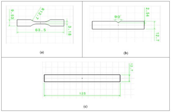
Figure 1. Standard specimens used for: (a) tensile test; (b) impact test; (c) flexural test [9].
In general, the mechanical properties of the FDM printed parts can be improved by using a filament with high strength and by optimizing the process parameters (such as extrusion temperature, printing speed, infill density for example). The two most commonly used materials for the FDM are Polylactic Acid (PLA) and Acrylonitrile Butadiene Styrene (ABS). When comparing the ultimate tensile strength of these two materials, it is PLA that shows the highest UTS [10]. However, it was found that under certain combinations of the process parameters, parts manufactured from PLA can have low mechanical properties and can be even weaker than that parts made from ABS. Therefore, a substantial amount of research investigated the optimization of the process parameters of the FDM with the aim to maximize the mechanical properties.
Additive manufacturing allows manufacturing parts that are either solid or with a partial infill known as “infill density” that can vary from 0% (hollow part) to 100% (solid part). The infill density can have different patterns such as honeycomb or rectilinear for example. The load-bearing capacity of a part should increase when increasing the amount of the material inside the part. This finding was reported by Jatti et al. (2019) [9] during testing of flexural and tensile strengths of parts. A similar trend was observed by Ramkumar (2019) [11] who tested the impact resistance of the specimen using a standard IZOD test. The infill pattern was found to be a rank 1 parameter affecting the strength of the part [10][12][13] (Radhwan et al. (2019), Vicente et al. (2019), Rodriguez-Panes et al. (2018)) when a tensile test is done. Melenka et al. (2015) [14] found that the infill density is the most significant parameter determining the tensile strength and elastic modulus of the printed part.
Similar results were observed on Young’s modulus. Alafaghani et al. (2017) [15] measured the elastic modulus under the tensile loading of the PLA part using 0.02% offset method and found that when the infill percent is increased from 20% to 100%, the tensile stiffness increases gradually from 2 to 2.5 GPa as shown in Figure 2. The same trend was obtained by Vicente et al. (2019) [13], who conducted a tensile test on the ABS parts. When the infill percent was increased from 95 to 105% (negative airgap), the part strength was increased from 700 to 720 MPa. In general, it was found that the PLA filaments were stiffer than ABS.
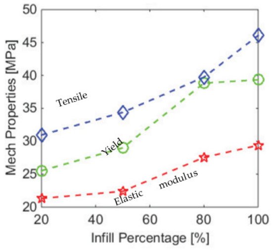
Figure 2. Dependence of the mechanical properties on the infill percent [15] (Alafaghani et al.).
The effect of the infill density may seem to be obvious, however, the abovementioned studies used the whole area of the cross-section to calculate the UTS. In fact, only part of the cross-section (which was infilled) bears the load as the cross-section was not solid (for infill smaller than 100%). Therefore, proper metrics should be developed to account for partial infill. To address this issue, Akhoundi et al. (2019) [16], investigated specific mechanical properties of parts tested and evaluated the mechanical properties of each part that were divided by their mass to account for the infill. Figure 3a,b shows the results for the flexural strengths as well as the corresponding stiffness modulus. It can be seen that the specific flexural mechanical properties (same properties divided by the mass of the part) are similar, which shows that the mechanical properties of the material are marginally affected by the infill density but the reduction of infill density will generate a decrease in the load-bearing capacity of the part. However, considering the tensile testing only, in most cases, the 50% infill is not as efficient as 100% and 20%. The specific tensile and flexural moduli are not affected to the extreme by the variation of the infill as the solid shell will provide the main strength of the part.
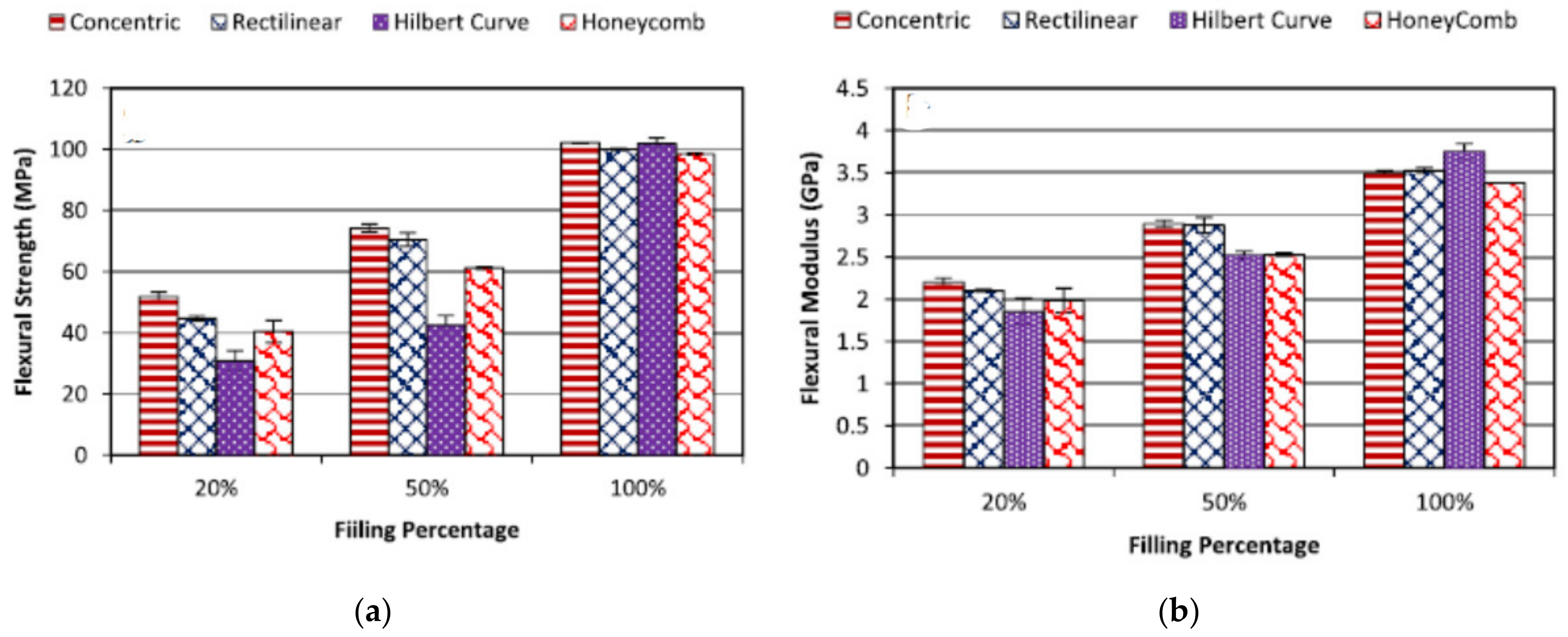
Figure 3. (a,b) Mechanical properties of the parts (Akhoundi, et al. 2019) [16].
Apart from the infill density, the infill pattern also affects the mechanical properties of the part. The infill pattern determines how the infilled filaments interact with each other while subjected to loading.
Alayoldi, et al. (2020) [17] investigated the effect of the infill pattern on the compressive strength of the part. It was found that triangular, grid and hexagonal infilled parts resulted in similar ultimate tensile strength (56–72 MPa), while the quarter cubic infill exhibited a significantly lower strength of 27 MPa. It was also found that the grid pattern had the highest tensile strength due to its special layer arrangement in which the infill layers are crisscrossed one above the other as shown in Figure 4. This was not observed for the case of quarter cubic pattern, in which there is an offset between the layers. When the part was loaded, this offset area was unsupported by the preceding layers and acted as a cantilever in bending. As a result, overall strength drops to 27 MPa.
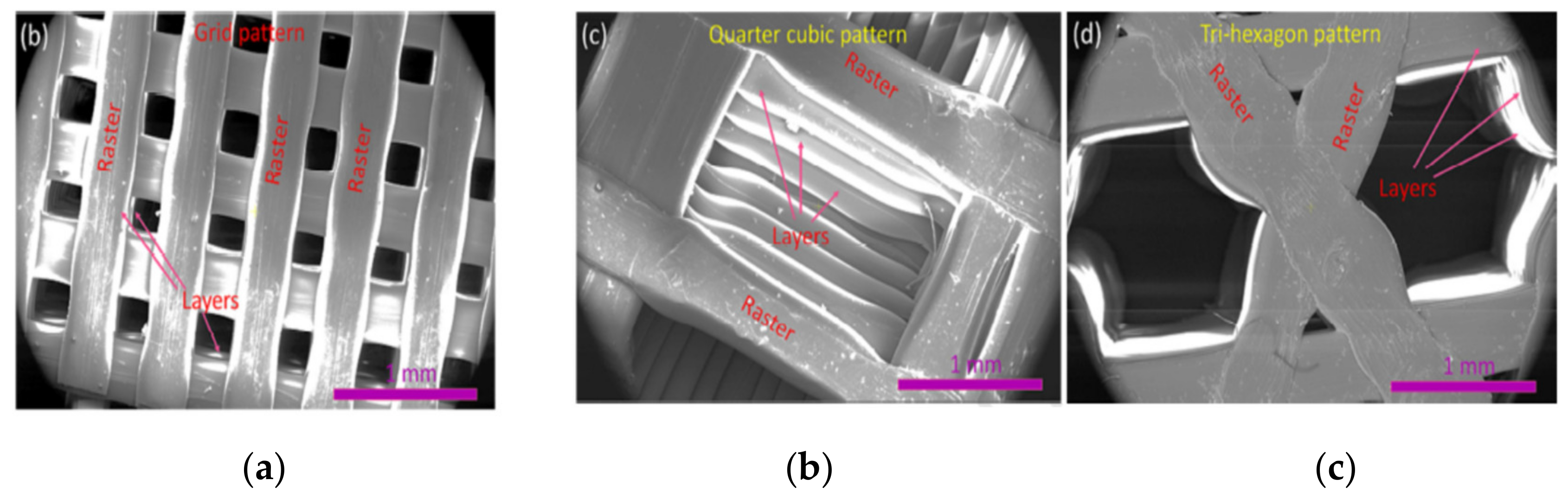
Figure 4. SEM images of various infill patterns: (a) Grid pattern; (b) Quarter cubic pattern; (c) Tri-hexagon pattern [17] (Alayaldi, et al. (2019)).
It was also found that using patterns in which layers are located on one another tends to make the part more brittle and lower its impact strength. A study involving the impact characteristics of the FDM-ed parts showed that a rectilinear pattern in which all layers are aligned has poorer impact resistance compared to the honeycomb infill pattern. This happened because the crack propagation in the honeycomb pattern is problematic due to variant raster orientation at 0, 60 and 120 degrees.
Similar results were reported by Chadha, et al. (2019) [18] who studied how grid, triangular and honeycomb infill patterns perform under the flexural and tensile loadings. It was found that the triangular pattern has the highest strength followed by the grid and finally by honeycomb patterns under both bending and tension. SEM images of the fracture surfaces indicated that in the case of the grid pattern, printed filaments did not change its circular cross-section. This means that those filaments did not experience any necking, which might be the evidence of the brittle fracture. However, honeycomb and triangular patterns failed in a ductile manner and their filaments’ cross-section became oval due to the necking.
Akhoundi, et al. (2019) [16] suggested that in order to increase the tensile strength on the part, either all filaments should be aligned with the load application direction or the fusion between adjutant fibers should be increased. Fusion continues as long as the filament temperature cools down to glass transition temperature (Wool, et al. (1981)) [19]. Hilbert’s curve infill pattern is based on this principle. It can be seen from the results obtained by Akhoundi et al. [16] that the highest increase of the tensile specific strength was observed in the case of Hilbert’s curve infill pattern, which involves short paths. When one of these paths was deposited, it did not have much time to cool down before the other path was deposited next to it. Thus, increasing the infill to 100% yields a dramatic rise in the strength from 28 MPa at 20% infill to 60 MPa at 100%. In this case, the fusion of the adjutant paths has the dominant effect on the overall strength. On the other hand, concentric infill pattern, the one in which load application and filament deposition directions are aligned showed superior results at all infill densities.
The findings by Akhoundi, et al. (2019) regarding the honeycomb pattern contradict the findings of Cwikla, et al. (2017) [20] who investigated that the ABS part filled with honeycomb pattern shows commensurable strength with concentric infill and 40% density. The concentric pattern was not recommended for torsional applications, because due to its symmetrical geometry the torsional stiffness will fall. At the same time, traditional grid and rectilinear patterns have detrimental effects on mechanical properties.
Due to conflicting findings, it appears that further research is needed to evaluate how infill patterns influence the mechanical properties of AM parts. Additionally, as new infill patterns are available, there is a need to investigate their behavior under several loading conditions.
The extrusion temperature, if properly set, can have a positive effect on the mechanical properties of a part. For improved mechanical properties, fusion between the new layer and the existing layers takes place before the extruded filament cools down below its glass transition temperature, and the longer it stays at a higher temperature than its glass transition level, the better the bond becomes. This might explain the reason why the mechanical properties of PLA parts are superior to those of the ABS. PLA with lower glass transition temperature as well as lower heat conduction coefficient fuses better with the adjacent layers and filaments.
The abovementioned correlation was verified by Coogan, et al. (2016) [21] who studied the bonding between extruded filaments. In their work, they printed hollow boxes with a thickness of one raster. Afterward, it was cut by a laser cutter to make test specimens. It was found that the increase in the extrusion temperature yields much stronger bonds. This happened due to increased wetting. At high temperatures, the fluidity of molten PLA increases, which facilitated the adhesion of the newly deposited PLA fiber on the extruded one and thus bond width between extruded raster increased which resulted in an increase in the strength as shown in Figure 5. Their study also concluded that in order to increase the bonding between filaments, wetting should be facilitated, and the diffusion time (time taken by the filaments to cool to glass transition temperature) should be increased. Dependence between diffusion time and process parameters was studied by Zhou, et al. (2017) [22] who used an IR sensor to obtain temperature history. Their study concluded that the increase in the nozzle and platform temperatures prolongs the diffusion time and hence this will result in increased bond strength as well as increased overall mechanical properties. However, temperatures were not as significant as printing speed which is the most dominant parameter.
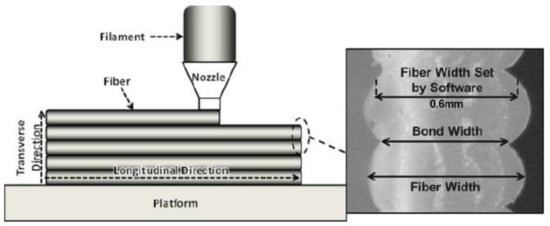
Figure 5. Bond width compared to fiber width [21] (Coogan, et al. (2016)).
Similar conclusions were derived by Jatti et al. (2019) [9] and Alafadgani et al. (2017) [13] as shown in Figure 6. It can be seen that both researchers found that an increase in the extrusion temperature positively influences the mechanical properties of the parts. However, the increase of the UTS with the increase of temperature as overserved by Jatti et al. [9] was not as rapid as in the case of Alafadgani, et al. [13]. This might be explained by the fact that different designs of the experiment were used. The latter work involved L18 Taguchi design, while the former research varied only in the extrusion temperature while keeping all other printing parameters constant. However, by observing the trend, it can be concluded that the strength–extrusion temperature relationship is not linear, and it reaches a maximum at around 200–220 °C, above 220 °C the mechanical properties start to deteriorate. A similar trend was observed in the study undertaken by Benwood, et al. (2018) [23], in which the tensile and flexural strengths increase with the extrusion temperature until they reached a maximum and stabilized at 200 °C. Jatti, et al. (2019) [9] found that an increase in the extrusion temperature can lead to the more brittle part. Similar results were obtained by Huynh, et al. (2019). Investigations using Taguchi’s optimization of the extrusion temperature, speed and layer thickness showed that the extrusion temperature is the most significant parameter (Rank 1) that influences the mechanical properties of the part.
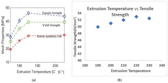
Figure 6. Effect of the extrusion temperature on the mechanical properties of the PLA part. (a) Extrusion temperature versus mechanical properties (Alafadgani, et al. (2017)), (b) Extrusion temperature versus ultimate tensile strenght (Jatti, et al. (2019)).
It should be noted that the following strength–extrusion temperature relationship is not limited to ABS and PLA materials. Ouballouch, et al. (2019) [24] studied the effect of the process parameters on the mechanical properties of the additively manufactured glass and Kelvar reinforced polyamide matrix composite parts. It was found that in both cases, the same trend was observed and the ultimate tensile strength of the parts increases with the temperature up to a certain limit.
The adverse effects of high extrusion temperatures were studied by Ning, et al. (2016) [25]. In their work, they used carbon fiber reinforced polymer (ABS is matrix material) and studied the effect of process parameters on the standard specimen. Fracture surfaces were then analyzed using SEM. It was found that as the extrusion temperature rises, the part becomes stronger, however after it increases above 220 °C, the mechanical properties suddenly drop. Figure 7 shows the SEM images of the fractured surfaces printed at temperatures 200–240 °C in 20 °C increment. As it was expected, the bonding between layers at low temperatures was poor (Figure 7a) and it improved up to 220 °C (Figure 7b). However, a further rise of temperature increased the fluidity of molten plastic, due to which the filaments lose their viscosity and void were constantly produced reducing the mechanical properties of the part (Figure 7c). These results were confirmed by Guessasma, et al. (2019) [26], who studied the effect of the printing temperature on the PLA-PHA plastic. The results showed that with the increase of the temperature up to 240 °C, the tensile strength and strain at break increased. However, as the temperature increased to 250 °C, the mechanical properties started to become poorer.
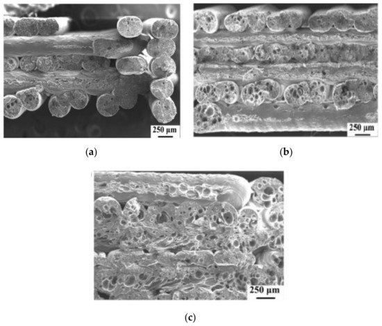
Figure 7. SEM images of the fracture surfaces printed at varying temperatures: (a) 200 °C; (b) 220 °C; (c) 240 °C [25].
The nozzle diameter also affects the mechanical properties of the parts produced by FDM. By controlling the nozzle size and layer thickness together it is possible to control the air gap between adjacent plastic strands. Its effect was studied in several works summarized below.
Kuznetsov, et al. (2018) [27], found that the strength across the printed layers (z-axis) is weaker than along the deposited filaments (x- and y-axis). In the first case, the strength of the bonding between the layers is a more contributing factor than the strength of deposited threads. It was found that at constant layer thickness, an increase of nozzle diameter resulted in higher flexural strength. Additionally, their results suggest that the strength increases with the layer thickness decrease. Hence, when the ratio of nozzle diameter to layer thickness increases, the contact surface between the layers increases as well resulting in higher ultimate flexural strength. This was confirmed by Vicente et al. (2020) [13] (already in the reference list), who also found an increase in the tensile strength and stiffness when the nozzle diameter was changed from 0.4 mm to 0.6 mm. This was explained, by the authors, by the gravitational force that helps to spread the melted plastic and it is more efficient for large nozzle diameters.
Triyono et al. (2020) [28] investigated the effect of nozzle diameter on the ultimate tensile stress (UTS) of 3D-printed PLA parts. The nozzle diameters used in this study varied from 0.3 to 0.6 mm. The layer thickness was set as 20% of the nozzle diameter. It was found that when the nozzle diameter is increased the UTS also increases. Using scanning electron microscope imaging, it was found that the increase in UTS was due to the reduction of the voids (air gaps) between adjusting strands. As the nozzle diameter was increased the raster becomes wider and the overlapping between neighbouring strands occurs and fused together during the solidification. This led to the reinforcement of the specimen. In this study, it was also found that the increase of UTS with the nozzle diameter occurs even if the layer thickness is increased (as the layer thinness is 20% of the nozzle diameter). This finding suggests that the ratio of the nozzle diameter to layer thickness proposed by Kuznetsov et al. is the parameter that influences the tensile strength of the part. Similar conclusions were obtained by Yang et al. (2018) using response surface methodology [29].
Nabipour and Akhoundi (2020) [30] investigated the effect of the nozzle diameter on the UTS of the ABS specimens using Taguchi-based design of experiments. It was found that for ABS material, unlike in their PLA counterparts, there is an inverse correlation between the nozzle diameter and UTS. When compared with other process parameters the contribution of the nozzle diameter to the UTS was the lowest. It must be noted that large nozzles, from 0.5 to 1.5 mm. In this study, the effect of the nozzle diameter to layer ratio was not investigated and the nozzle diameters used were larger than the ones used by Kuznetsov et al. and Triyono et al. This might be one of the possible reasons for the discrepancy between the results.
In conclusion, from the literature, it appears that the ratio of the nozzle diameter to the layer thickness may be a major factor affecting the UTS and Flexural strength of the FDM printed parts. However, it seems there are some limitations that need to be further investigated. In addition, there are currently limited data available on the effect of the nozzle diameter or nozzle diameter/layer thinness ratio, on the impact and compressive strength. Therefore, there is a need for further investigation in this field.
It was shown that the layer thickness also influences the strength of the printed part. On the one hand, it was found in the literature that the tensile strength of both PLA and ABS filaments decreases as the layer thickness increased. On the other hand, the impact resistance and compressive strength of parts were found to have a direct relationship with the layer thickness parameter. This means the compressive strength is improved by using larger layer thickness. This relationship might not be true for the low levels of infill density parameter as the large voids inside the parts may decrease the compressive strength. Therefore, the interaction between various process parameters should be considered depending on the loading of the part as well as specific printing conditions. Moreover, it was found that this parameter has less effect on the strength of ABS parts and is more prominent for PLA filaments.
With increasing the layer thickness for PLA specimen subjected to tensile test, its UTS decreases (Jatti et al. (2019)) [9]. Similar results were found by Randriguez-Panes et al. (2018) [20] and Coogan et al. (2016) [31]. This might be explained by the fact that with the decrease of the layer thickness, the molten plastic extruded from the nozzle is compressed between the nozzle and platform or existing layer. Thus, instead of keeping its cylindrical shape, it deforms plastically and its cross-section becomes oval. This increases the contact area (bonding width) and wetting and therefore a fusion of the filament becomes better as shown in Figure 8 (Coogan et al. (2016)) [31].
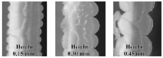
Figure 8. Increase in contact area with the increase in layer thickness (Coogan et al. (2016)) [31].
Similar findings were obtained by Garzon-Hernandez et al. (2019) [32]. They developed coupled simulation first to find the temperature history of the deposited filament and then use this result to predict the void ratio in the cross-section. This numerical parametric investigation suggested that the increase of the layer thickness causes the decline in strength and Young’s modulus.
Alafadgani et al. (2017) [15] suggested that the increase in the layer thickness will increase the mechanical properties due to the fact that a smaller number of layers is needed.
While having a smaller layer thickness in the FDM-ed part subjected to tension is beneficial, this is not a case for compressive and impact loadings. Sharma et al. [33] found that increasing the layer thickness from 0.1 mm to 0.3 mm caused an increase of the compressive stress from 33 to 42 MPa. This was attributed to the fact that during the compression the specimen fails due to shear stress caused on the principal plane. The increased number of layers (lower layer thickness) is more prone to such failure mode. Jatti et al. [9] also found that the impact resistance of the part decreased with the reduction of the layer thickness. This finding is in agreement with the results of Ramkumar (2019) [11].
The dependence of the strength on layer thickness seems to be more difficult to establish than the extrusion temperature previously. Oubalouch et al. (2018) [14][34] investigated the effect of the layer thickness on the mechanical properties of the PLA part for different infill densities. While the combination of lower thickness–higher strength was true for infill densities of 50% and 100%, this was not true for a 10% infill density. The ultimate tensile strength increased from 30 MPa to 40 MPa when the layer height was increased from 0.2 to 0.3 mm. The underlying mechanism behind this was not provided by the authors and therefore further research on the layer thickness effect at low infill density level is needed to confirm and explain these results.
Finally, the effect of the layer height seems to be also dependent on the filament material. It was found that the ABS part was marginally sensitive to the effect of the layer thickness. Randriguez-Panes, et al. (2018) [10] compared this effect on ABS and PLA filaments and found that in the case of ABS material the effect of the layer height is insignificant, while in the case of PLA, the result agrees with the abovementioned findings. Similar results were also obtained by Samykano et al. (2019) [35]. It appears that this due to the inherent properties (chemical and mechanical) of the filament material. However, the causality of this phenomenon is still yet to be explained. Table 1 presents a tabulated summary of the finding of the effect of layer thickness on the mechanical properties of a part.
Table 1. Effect of the layer thickness on the mechanical properties.
| Source | Material | Type of the Test | Remarks |
|---|---|---|---|
| Jatti et al. (2019) [9] | PLA | Tensile and flexural strengths, Impact resistance | Increasing infill density increases tensile and flexural strengths of the specimens, due to more material resists the force. |
| Alafaghani et al. (2017) [13] | PLA | Tensile strength, yield strength, Young’s modulus | Increasing LT increases mechanical properties. |
| Huynh et al. (2019) [36] | PLA | Tensile strength | Decreasing layer height will increase the strength of the part. Layer thickness is the rank 2 parameter |
| Sharma et al. (2019) [33] | ABS | Compressive and tensile strength | Increasing the LT decreases the tensile strength, while increases compressive Strength. |
| Samykano et al. (2019) [24] | ABS | Tensile strength | Layer thickness has no effect and was not a statistically significant parameter |
| Coogan et al. (2016) [31] | ABS | Tensile strength of the bonds | Layer thickness is the most significant parameter affecting bond strength |
| Randriguez-Panes et al. (2018) [10] | ABS and PLA | Tensile strength | In the case of PLA, lower layer thickness was desired as it produces the highest strength. In the case of ABS, LT was not significant. |
Most of the studies primarily investigated the effect of raster angle on tensile, flexural, and impact strength of ABS printed parts. It was reported that the minimum level (0°) of raster angle improves the tensile strength of FDM parts, while the impact strength can be improved using a 45°/−45° (staggered raster) raster angle. Wang et al. (2007) [37] studied the effect of raster angle on the tensile strength of ABS printed parts using the different three levels of raster angle (0°, 45°, and 90°). The experiment was designed according to the Taguchi L18 array. The findings of the author support the previous studies showing the 0° raster angle as an optimal level. In this article, the minimum level raster angle resulted in the maximum tensile strength of 24.36 MPa. Durgun and Ertan (2014) [38] also investigated the effect of raster angle on the tensile and flexural strength of ABS parts using five levels (0°, 35°, 45°, 60°, and 90°) of the parameter. Their conclusions appear to be consistent with the previous literature reporting that the 0° raster improves the mechanical strength of FDM parts because of the larger raster length values. Nidagundi et al. (2015) [39] studied three levels of the raster angle parameter, namely 0°, 30°, and 60° using Taguchi L9 orthogonal array design and ABS resin material. The results of the SN ratio demonstrated that the ultimate tensile strength of parts decreases as the raster angle increases. Therefore, the authors concluded that the 0° raster angle is the optimal level in terms of tensile strength along with 0.1 mm layer thickness and 0° part orientation. The maximum tensile strength of 27.674 MPa was obtained using the minimum levels of three parameters as mentioned earlier.
Similarly, Panda et al. (2009) [40] and Sood et al. (2010) [41] studied the same three levels of the raster angle as Nidagundi et al. (2015). Their experiments were conducted using a central composite design and ABS plastic was used in both studies. However, the optimal level of raster angle in terms of tensile and impact strength was found to be almost 60°. Panda et al. (2009) [40] found that 54.7311° raster angle was optimal for increasing the flexural strength of parts. This was because smaller raster angles result in longer rasters that serve as the stress concentrators. This in turn causes weaker bonding and leads to poor mechanical performance.
Onwubolu and Rayegani (2014) studied the influence of the raster angle on the tensile strength of FDM printed parts using ABS resin. The two levels of the raster angle, 0° and 45°, were selected. The experiment was designed using the full factorial design and the differential evolution method was implemented to identify the optimal levels of process parameters. The main findings show that there is a direct relationship between raster angle and tensile strength of printed parts. For example, the tensile strength of parts using 0° and 45° raster angles were 32.56 MPa and 34.61 MPa, respectively. The other parameters such as layer thickness (0.127 mm), part orientation (0°), raster width (0.2032 mm), and air gap (−0.00254 mm) were kept constant. Nevertheless, it should be noted that with the increase in raster angle value there is an insignificant improvement (2.05 MPa) in the tensile strength property. Moreover, the findings of Zieman et al. (2015) [42] further support the previous literature that found 0° raster angle as the optimal level in improving the tensile behavior of ABS printed parts. The experiment was conducted using four levels of raster angle: 0°, 45°, 90°, and 45°/−45° (the latter represents the crisscross raster). The mean ultimate tensile strength was found to be a maximum of 25.15 MPa using 0° raster angle, whereas this value for 90° raster orientation was 9.16 MPa. This is because tensile strength depends on the alignment between the axis where the stress is applied and the fiber axis of printed parts. Therefore, increasing the raster angle results in a misalignment between two axes causing weaker parts in terms of tensile strength. The fatigue test result for parts printed using different raster angles is shown in Figure 9. It was found that the default setting of the raster angle parameter (45°/−45°) results in the longest mean number of cycles to failure. The second-best level of raster angle was 0° in terms of fatigue strength.

Figure 9. The tension–tension fatigue test results for acrylonitrile butadiene styrene (ABS) parts with different raster orientation: longitudinal (0°), default (+45°/−45°), diagonal (45°), and transverse (90°) [42].
In the case of PLA resin, Liu et al. (2016) [43] found that the raster angle of 0° is optimal and results in the highest tensile and flexural strength. The authors studied three levels of raster angle such as long-raster (0°), long-short-raster (+90°/0°), and staggered-raster (+45°/−45°). The long-short-raster means layer with 90° raster angle is followed by a consecutive layer with 0° raster angle during the printing process. Based on the results of ANOVA analysis that demonstrates the percentage contribution of parameters, it was found that the raster angle parameter mostly affects the impact strength (0.127%) of PLA parts compared to tensile (0.002%) and flexural strength (0.034%). The optimal level in terms of the impact strength was found to be staggered-raster (+45°/−45°).
The build orientation refers to the orientation of the printed parts with respect to the z-axis. Usually, the x-y plane is considered as the build platform area and the z-axis refers to the height of the printed parts. Most research indicates lower levels (0° or 15°) of build orientation to be optimal in terms of the tensile strength of FDM parts, whereas the flexural and impact strength properties show different optimal orientations in different studies. Zhou et al. (2017) also reported on the effect of build orientation as an important parameter to be impacting mechanical properties. Their study reported that the FDM part having the filaments deposited in load direction (mode II) exhibits higher tensile strength compared to the FDM part with fibres oriented in the transverse direction (mode I). The reason behind this was explained as follows. Filaments themselves can resist the load when oriented in the load direction, while filaments oriented in the transverse direction have only the bonding forces between them to resist the load. Mode III combination of mode I and mode II shows intermediate outcome [44]. Nidagundi et al. (2015) [39] reported the effect of build orientation on the ultimate tensile strength of ABS parts. The authors studied this parameter using three levels of control such as 0°, 15°, and 30°. The experimental results showed that the mean SN ratio decreases as the orientation angle increases and the larger SN ratio represented better tensile strength. This means 0° build orientation is considered as optimal in terms of the ultimate tensile strength of FDM printed parts. Apart from that, the influence of the build orientation parameter on the tensile strength of parts was reported to be 37.33% and thus being the most influential parameter compared to layer thickness and fill angle parameters. Raju et al. (2018) [45] also used SN ratio plots to study the effect of build orientation on the mechanical performance of ABS parts. On the contrary to previous studies, among the three levels (30°, 60°, and 90°) of control, 60° build orientation is found to be optimal in terms of both tensile and flexural strength of parts.
Vishwas et al. (2018) [46] studied the build orientation effect using resins such as ABS and Nylon. The main findings show that the ultimate tensile strength was maximum (26.41 MPa) for ABS printed part using 0.1 mm layer thickness, 15° orientation, and 1.2 mm shell thickness. The contribution of the build orientation parameter to the tensile strength of parts was 72.41% among the three process parameters. In the case of Nylon resin, the maximum ultimate tensile strength (25.48 MPa) was attained using 30° build orientation in combination with 0.1 mm layer thickness and 1.2 mm shell thickness. Another comprehensive study of the build orientation parameter found that the lowest build orientation is optimal for the tensile strength of ABS parts (Raut et al., 2014) [47]. The authors studied the three different levels of build orientation (0°, 45°, and 90°) with respect to each of x, y, and z-axes separately. The results demonstrated that the maximum tensile strength can be observed when the build orientation parameter is set to 0°. For example, 35.45 MPa, 22.51 MPa, and 33.00 MPa tensile strength values were reported using 0° build orientation with respect x, y, and z-axes, respectively. In the case of the flexural strength, the higher build orientation levels resulted in better flexural strength values excluding the x-axis. The maximum flexural strength of 45.20 MPa was noted using the 0° build orientation with respect to the x-axis. The illustration of the relationship between the tensile and flexural strength of ABS parts and different build orientation levels with respect to x, y, and z-axes is shown in Figure 10.
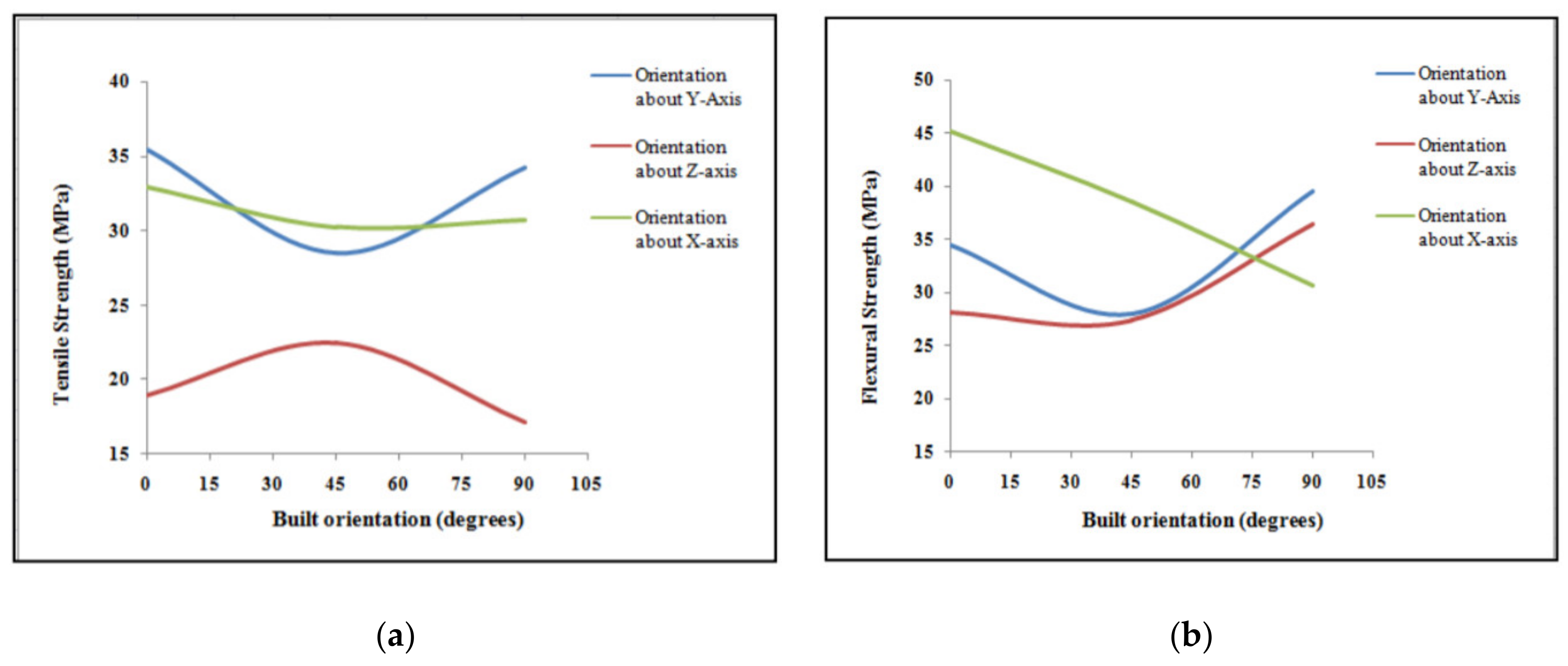
Figure 10. The mechanical strength of ABS printed parts using different build orientation levels: (a) Tensile strength; (b) Flexural strength [47].
Hernandez et al. (2016) [48] selected five different levels of build orientation parameter such as 0°, 45°, 90° in the XY plane and 45°, 90° in the Z plane. The mechanical strength of ABS parts was addressed in terms of tensile, compressive, and flexural strength results. The primary findings showed that the maximum tensile strength of 10.8 MPa was achieved using 90° in the XY plane. Despite this, the minimum tensile strength value was 9.36 MPa using 90° in the Z plane. This implies that the tensile strength of parts is less affected by the build orientation parameter. On the other hand, the compressive and flexural strength of parts were found to be highly dependent on this parameter. The compressive strength increased from 29.4 MPa (using 45° in the XY plane) to 59.3 MPa (using 0° in the XY plane). The maximum flexural strength of 122 MPa was also observed using 0° in the XY plane. Wang et al. (2007) [37] analyzed the effect of the build orientation parameter on the tensile strength of ABS parts using Taguchi L18 orthogonal array design and Gray theory to find an optimal process parameter. The one notable difference of this study is that the authors addressed build orientation as a categorical parameter and used the following three levels: L (the length of the printed part is the lowest in the z-axis), H (the length in the z-axis is the highest), M (the length of the parts in the z-axis is between L and H). Among the investigated six process parameters, only build orientation was found to have a significant impact (77.16% contribution) on the tensile strength of parts according to the ANOVA analysis. The maximum tensile strength of about 24 MPa was noted using M (medium) level of build orientation while L (low) and H (high) levels resulted in nearly 15 MPa and 14 MPa, respectively.
Abdelrhman et al. (2019) [49] investigated the build orientation using PLA resin and five levels of control as follows: X0°Y0°, X90°Y0°, X0°Y90°, X0°Y45°, and X90°Y45°. The tensile strength and maximum fracture load of printed parts were considered as the output of the experiment. Both the maximum average tensile strength of 29.36 MPa and fracture load of 1409.09 N were achieved using X0°Y0° build orientation. It was noted that the mechanical behavior of PLA parts worsens as the Y-component of build orientation increases. For example, the minimum average tensile strength (14.71 MPa) was noted using X0°Y90°. Liu et al. (2016) also studied the effect of build orientation on PLA printed parts using the following levels of control: 0°, 60°, and 90°. The results of the Taguchi L27 design experiment showed that 0° build orientation is the optimal level in terms of tensile, flexural, and impact strength of FDM parts. This was confirmed by implementing grey relation analysis. The maximum tensile (50.34 MPa), flexural (83.51 MPa), and impact (23.07 MPa) strength values were obtained using the following optimal combination of process parameters: 0° build orientation, 0.3 mm layer thickness, 0° raster angle, 0.5 mm raster width, and −0.1 mm raster gap.
Fused deposition modeling (FDM) as any other technologies has limitations such as low structural strength and surface finish (stair-stepping effect) of the parts. Although manipulation of process parameters makes significant differences in the quality and mechanical properties of the printed part, the ideal combination of parameters is almost impossible to achieve (Popescu, 2018) [50]. According to Hongbin Li et al. (2016) [51] infill rate, deposition velocity and layer thickness highly affect the result of the manufacturing process. Enhancing one parameter usually sacrifices the other. For example, to increase interlayer bonding the layer thickness must be decreased, thus resulting in a longer printing time [51] (Li, 2016).
One of the main concerns arising is due to anisotropic behavior of the extruded layers and the part in general. This issue is generally attributed to poor inter-layer bonding. One of the solutions for increasing the mechanical properties of the printed parts without sacrificing the other parameters is preheating of the extruded layer. The principle is to preheat the extruded layer (existing later) before the next layer is deposited. This can be ensured by different kinds of light sources such as laser or infrared light for example. The preheating of the surface of the already extruded layer up to the glass temperature in order to increase the bonding between layers was proposed by Kishore et al. (2017) [52] (Kishore, 2017). Several methods of preheating with various light sources, materials and printing parameters have been investigated. Each method has been studied and analyzed. A comparison table (see Table 2) summarizes the different techniques.
Kishore et al. (2017) developed one of the approaches that has been proposed for enhancing the quality of the printed parts. The methodology of this experiment was applied for big area additive manufacturing systems (build volume 6 m × 2.5 m × 1.8 m) with an infrared lamp as a light source. Material that was used during this experiment—fiber reinforced thermoplastic pellets (acrylonitrile butadiene styrene (ABS) reinforced with 20 wt.% short carbon fiber) instead of filament to optimize the cost [52] (Duty, 2017).
The effect of lamp power was investigated by three different experiments where the position and intensity of Infrared lams varied. For the first condition, print speed was varied (3.8 cm/s, 5.1 cm/s, 7.6 cm/s) and two 50 W IR lamps were arranged at an angle to maintain the printed surface 8 cm away from the lamps. Figure 11a shows the results of the experiment. At 3.8 cm/s the result of the average fracture energy becomes more than doubled after heating the layer. A similar result was achieved at the second speed variation; however, the last run reported a slight decrease in the average fracture energy after preheating compared to the initial value for the non-heated run. For the first two cases, the printing speeds were relatively low, therefore more cooling of the surface was compensated by preheating, nevertheless, the speed was higher for the third case, and hence the plastic did not have time for overcooling, thus improving the “non-heated” results.
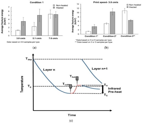
Figure 11. (a) Variation of fracture energy with print speed (b) Variation of fracture energy for various pre-heating conditions (c) Schematic of time–temperature profile. (Kishore, 2017) [52].
At this time, condition 2 had the same IR lamps but placed at a distance of 2.5 cm away whereas condition 3 used 1 kw IR lamp (single 6.35 cm long) placed at a distance of 1 cm above the deposited bead.
The comparison of three conditions with varying heating arrangements but with the same speed setup (3.8 cm/s) was also reported in Figure 11b. Preheating for the first and the second condition increased the average fracture energy more than twice. However, the third condition showed poor results, due to the small distance between the light source and layers which led to the plastic degradation and eventual reduction in tensile strength in the z direction [53]. One of the problems faced during these experimentations was the inability to preheat the extruded layer to the desired glass transition temperature. Figure 11c demonstrates the temperature profile with preheating by IR lamp. Large part usually suffers from long layer time and therefore experiences cooling of the layer below glass transition temperature from the deposition temperature. With the incorporation of IR lamps, substrates temperature can be elevated closer to the glass transition temperature just before the next layer deposition and thus enhances the interlayer bonding strength. However, the competency of the preheating largely depends on the lamp intensity as well as lamp orientation, standoff distance, and printing speed as well. On the other hand cooling rate of substrates depends on ambient temperature, geometry variation, tool path pattern and thermal conductivity of the materials [54].
In order to avoid the excessive heating experienced by some preheating conditions previously, Kishore et al. (2019) [53] also developed an artificial cooling system to cool down the extruded layer before exposing it to the IR light. The temperature was decreased by forced convection down to 40°C, 60°C and 80°C with the variation of the active cooling cycle. The idea was to always start heating the surface from the set temperature in order to achieve 150 °C. This technique prevented plastic from overheating, thus reducing the risk of plastic degradation. The average tensile strength in z-direction was increased by 81% for Tcold = 40°C.
Another approach of enhancing FDM printing was developed by Meng Luo. It was based on “laser assistance”. The CO2 laser device (40 W) was implemented into a traditional FDM printer. The setup required additional mirrors to locate the laser beam on the extrusion path. Control of the mirrors makes the entire system more complex. (Luo, 2018) [55]. Interlayer shear strength was directly affected by the preheating as shown in Figure 12. Preheating results in a small enhancement in interlayer bonding for the temperature of the laser point less than glass transition temperature. However, temperature over glass transition temperature results in significant improvement. Interlayer shear strength polyether ether ketone (PEEK) was improved up to 45% however, other laser power variations resulted in poor outcomes. The optimal laser power should be 15% of the full power. For the complete understanding of the effect of the parameters on the sample’s properties, parameters such as laser power, laser focusing angle and printing speed are needed to be analyzed further.
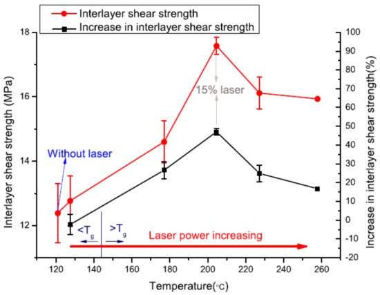
Figure 12. Interlayer shear strength and percentage increase of interlayer shear strength with different interlayer bonding point temperatures (Luo, 2018) [55].
Ravi et.al (2016) also implemented preheating apparatus for obtaining better results in terms of isotropy. Equipment was set up based on the commercial open-source 3D printer (Ravi, 2016) [56]. A combination of the laser and optic system was used as a light source (laser with the power of 2 W). Installation of the mirrors was added on the platform. It was determined that at lower printing speeds, the laser provides an excessive amount of energy to the plastic, thus causing degradation and defects. In order to analyze the effect of preheating on flexural strength, bending tests were performed. The design proposed by these researchers showed a 50% increase in the strength of the interlayer bonding. In addition to that, the ductile behavior of the plastic after preheating was also noted. As can be seen from Figure 13a, a sample without laser preheating experiences brittle fracture at the point where a sharp drop in bending load occurs at the end of the linear load–deflection curve, whereas for preheated sample, failure occurs in a ductile manner at the end of the linear load–deflection curve due to the increased bond potential as raised by increased temperature as well as interpenetrating diffusion. In addition, optical images in Figure 13b show the clear improvement of bonding strength with respect to nonheated FDM printed sample. In the case of the laser-treated sample, a more uniform profile suggests the reflow of substrate material due to heating which promotes the diffusion mechanism and therefore reduces defect between the layers subsequently.
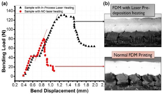
Figure 13. (a) Bending load–deflection plot (b) Optical micrograph of freeze-fractured control samples and those using the in-process laser pre-deposition heating approach (Ravi et al., 2016) [56].
Du et al. (2016) [57] deployed two laser sources for preheating, post-heating (Figure 14) or lateral heating in case of large thin-walled part fabrication. Two-directional heating is the main advantage of this setup. Results of this approach have been generated by simulations based on governing equations. Semi-implicit pressure-linked equation algorithm was implemented to simulate FDM printing. The flow of the melted plastic was taken into account by Navier–Stokes and energy equations (Du, 2016). Laminar incompressible flow assumptions were also made. A 195% increase in the tensile strength was achieved by the lateral laser-assisted heating. For the same printing speed and laser power, lateral heating is reported to be more effective in achieving higher bonding strength compared to pre- and post-heating. Effective bonding width was reported to be increased by 24% using pre- and post-laser heating. The optimal value of speed ratio (wire feed rate vs printing speed) was determined to be 0.75. The optimal value of the layer thickness was found to be 0.25 mm (Du, 2016) [57].
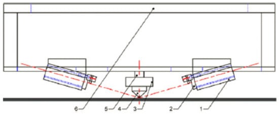
Figure 14. Experimental setup (1) fixing equipment; (2) infrared laser; (3) nozzle heater; (4) nozzle; (5) filament source; (6) frame (Du, 2016) [57].
Sabyrov et al. (2020) also proposed the application of a 5 W diode laser for preheating the surface of the extruded layer due to the waste of power involved in heating big areas of the layers. Their setup does not require additional components such as mirrors as shown in Figure 15a. Additionally, the setup proposed by Kishor et al. (2019) is not applicable to common FDM equipment. Sabyrov et al. (2020) reported a 10.16% increase in ultimate tensile strength at a 2.84 W power laser (Figure 15b). However, the quality of the parts seems to be very poor. Cracks and holes were evident in the part due to intensive laser heating. Since the result associated with 1.66 W and 2.84 W laser are the best and are not very different from each other, Sabyrov et al. (2020) suggested using a 1.66 W laser to reduce energy consumption. In addition, the color of the plastic can also influence the performance as darker material absorbs more energy compared to light color materials. Further investigation is needed in the following areas: printing speed, direction angle, size of the focal point of the laser, laser diode-based heating on the bending parameter [58].
Table 2. Summary of Enhancement techniques.
| Articles | Material | Printing Speed (cm/s) | Deposition Temperature | Light Source | Power of the Light Source | Preheating Temperature |
|---|---|---|---|---|---|---|
| (Kishore et al., 2017) [52] | Acrylonitrile butadiene styrene (ABS) reinforced with 20 wt.% short carbon fiber | 3.8, 5.1, 7.6 | 215 °C | Infrared lamp 500 W for case 1 and 2 1 kW for case 3 |
100% for case 1 and 2 80–90% for case 3 |
N/A |
| (Kishore et al., 2019) [53] | Acrylonitrile butadiene styrene (ABS) reinforced with 20 wt.% short carbon fiber | 5.1 | 215 °C | Strip IR model number 5306B-02-1000-01-00 (the same lamp that was used for case 3 previously) |
80% | 150 °C |
| (Luo et al., 2018) [55] | semicrystalline thermoplastic polymers | 0.6 | 410 °C | 40 W CO2 laser (10.6 μm wavelength) | 5, 10, 15, 20, 25% | Varied with the power of the light source |
| (Ravi, 2016) [56] | black-color ABS filaments | 0.1–1 | 230 °C | 802 nm solid-state laser (2 W) | 0.75 W | Varied with the power of the light source |
| (Du, 2016) [57] | ABS polymers | 1–2 | Not specified | Laser (2 W) | 0–2 W | By 20–30 °C |
| (Sabyrov, 2020) [58] | PLA plastic | 3.5 | 210 °C | Diode laser (5 W) | 1.47, 1.66, 1.96, 2.25, 2.55, 2.84 W | Varied with the power of the light source |
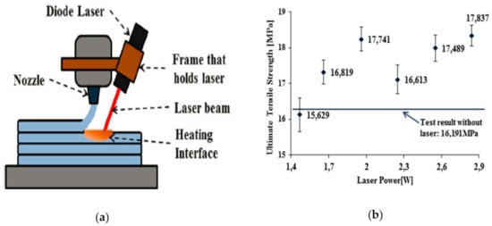
Figure 15. (a) Equipment setup (b) Ultimate stress vs. laser power graph [58].
Since warpage and porosity of printed part are impacted by environmental temperature and humidity, some research suggested to use heated printing chamber to improve the FDM printed part quality. Fang et al. (2020) investigated the impact of environmental temperature and reported that temperatures from 30 °C to 90 °C could potentially improve the mechanical properties along printing direction due to reduced warping defect [59]. Sun et al. additionally experimented with the impact of built chamber temperature on polyether ether ketone (PEEK) polymer and reported profound improvement in the printed part strength [60]. Sproerk et al. (2018) also reported a similar finding and suggested the occurrence of annealing with reduced warpage of printed part as a result of enhanced printing chamber temperature [61][62]. Carneiro et al.(2019) [63] and Armillotta et al. [64] also suggested the reduced structural porosity due to increased chamber temperature close to the glass transition temperature.
It is also evident that mechanical properties are negatively influenced by the presence of pores in the structure which helps crack propagation [65]. Since the percentage and volume of pores increase with the increased water content, the mechanical strength of the printed part decreases in both longitudinal and transverse loading directions in the presence of moisture content, however, some improved ductility may be observed [66]. Moisture content also reduces the glass transition temperature. Fang et al. (2020) in their work suggested not only the prior drying of the filament but also to maintain a dry heated environment during printing (below 30% RH) for better mechanical properties. Their result suggested 30% reduced strength in the longitudinal direction and 70% reduced strength in transverse directions with filament with moisture content with respect to dried filaments [59].


