1000/1000
Hot
Most Recent
 +1 point
Optical fiber current sensor is a kind of smart grid equipment, and its principle utilizes the magnetostrictive effect of magnetostrictive materials.
With the rapid development of intelligent power grid technology, optical fiber current sensors play an important role in power measurement, monitoring, and protection. Optical fiber current sensors have the following inherent characteristics: anti-electromagnetic interference, electrical isolation, small size, and light weigh. At the same time, the measurement object of the optical fiber current sensor is a magnetic field generated by the current, not the current itself, which avoids the danger of high voltage measurement[1].
The proposed sensor is composed of a magnetic circuit sensing system and photoelectric testing system. The magnetic circuit sensing system is composed of magnetostrictive materials (magnetostrictive composite materials), fiber gratings, magnetically permeable materials, and permanent magnets. The photoelectric test system consists of a light source, a circulator, and a spectrum analyzer. The magnetostrictive material is combined with the fiber grating and placed in the magnetic field generated by the current, and the change of the current can be obtained by demodulating the wavelength drift of the fiber grating[2]. This paper studies the magnetostriction phenomenon and its causes, the working principle of fiber grating, and the role of permanent magnets.
Magnetostrictive materials extend (or shorten) in size under the action of external magnetic field, and then return to their original size after the external magnetic field is eliminated. This phenomenon is called magnetostriction. Since this phenomenon was first discovered by Joule in Ni materials, it is also called the Joule phenomenon or Joule effect[3]. Magnetostriction refers to geometric deformation caused by externally applied magnetic field[4]. The magnitude of magnetostriction is expressed by the magnetostriction coefficient l = DL/L, where DL refers to the variation of material length and L refers to the overall length of material, as shown in Figure 1.
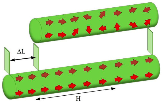
Figure 1. Magnetostriction phenomenon.
The causes of magnetostriction are shown in Figure 2[5]. Magnetic materials can be divided into numerous magnetic domains microscopically. When external magnetic field intensity is 0, the magnetic moment directions of magnetic domains are different, but the vector sum is zero, and the magnetic moment of the whole object is zero, which indicates that the material is not magnetic in the macroscopic view, i.e., the material does not deform. When the magnetic domain is in an applied magnetic field, it will deviate from the original self-magnetization direction and deviate towards the direction of the applied magnetic field. When the magnetic domain deflects in the same direction, a magnetic field force will be generated in this direction, which will cause the ferromagnetic material to be deformed by the force in this direction, resulting in magnetostriction. Within a certain range, magnetostriction of ferromagnetic materials will increase with the increase of the applied magnetic field, but when the applied magnetic field exceeds a certain range, magnetostriction basically remains unchanged, i.e., the deformation (strain) of the material reaches saturation[6].
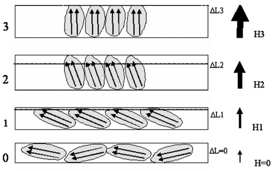
Figure 2. Schematic diagram of magnetostriction.
After cleaning the surface of the magnetostrictive material, the fiber Bragg grating (FBG) was bonded to the magnetostrictive material with cyanoacrylate adhesive. When the current generates a magnetic field, the magnetostrictive material in the magnetic field will be deformed, and the deformation will be transferred to the bonded FBG.
The function of FBG is essentially to form a narrowband (transmission or reflection) filter or mirror in the fiber core, as shown in Figure 3. When a beam of broad-spectrum light passes through the fiber grating, the wavelength meeting the Bragg condition of the FBG will be reflected, and other wavelengths will continue to transmit through the fiber grating. The formula of center wavelength is[7] [11]:
|
|
(1) |
where L is the grating period, and neff is the effective refraction of FBG.
When the FBG is subjected to axial stress, it will be strained, and the period and refractive index of the FBG will change. At this time, the relationship between the central wavelength change of the FBG and the strain is as follows:
|
|
(2) |
where Pc is the effective photo-elastic coefficient, which e is about 0.22 for the silicon fiber medium.
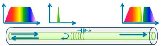
Figure 3. Schematic diagram of fiber grating.
Magnetostrictive materials have unipolar characteristics, i.e., the expansion and contraction of magnetostrictive materials is only related to the magnitude of the applied magnetic field, but has nothing to do with its direction. When the applied magnetic field is an alternating magnetic field, although the directions of the positive and negative half-cycles are opposite, the expansion and contraction directions of magnetostrictive materials excited by the two half-cycles are the same. The unipolar characteristics of magnetostrictive materials make a frequency-doubling effect appear in the working process, as shown in Figure 4.
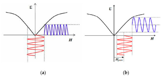
Figure 4. Influence of frequency doubling on magnetostrictive materials. (a)“frequency doubling” phenomenon. (b) no “frequency doubling” phenomenon.
Permanent magnets are added to the magnetic circuit to provide a constant magnetic field. Under the action of a constant magnetic field, the total magnetic field applied to magnetostrictive materials is all positive or all negative. Therefore, the permanent magnet avoids the influence of the unipolar characteristics of magnetostrictive materials, and enables the sensor to obtain a complete alternating current (AC) cycle, as shown in Figure 5.
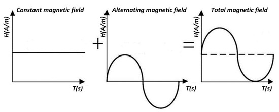
Figure 5. Role of permanent magnets.
Figure 6 shows the experimental setup for evaluating the performance of the sensor. An AC-band amplified spontaneous emission (ASE) source or a tunable laser (Agilent 81640B), combined with a 3 dB coupler, was used to illuminate the MC-FBG sensor via ports 1 and 2 of an optical circulator. The reflected wavelengths via ports 2 and 3 of the optical circulator were split by a 3 dB coupler and then measured by a 125 MHz photodetector (NewFocus 1811) or an optical spectrum analyzer (OSA) (Agilent 86140A) with a 0.1 nm resolution. The electromagnet provides a quasi-static magnetic field with a maximum amplitude of 146 kA/m and a frequency of 1 Hz. The function of the spectrum analyzer is to demodulate and display signals[8].
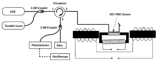
Figure 6. Sensor system diagram.


