1000/1000
Hot
Most Recent
 +1 point
An endoscope is an imaging device made up of a long and thin tube that can be inserted into the hollow openings of the body to image the inner sections in real time and in a less invasive manner.
Advances in fiber optic systems led to the development of flexible endoscopes, enabling high-resolution images of narrow sections of the body and reducing the number of biopsies required for a specific diagnosis, with applications such as cancer detection, microvascular oxygen tension measurement, chronic mesenteric ischemia, subcellular molecular interactions, etc. Earlier developed standard white light endoscopes (WLEs) had limited ability to differentiate metaplasia from dysplasia. Such limitations were surpassed by enhancing the image contrast through the use of dyes in chromoendoscopy or applying digital filters in narrow band imaging (NBI) [1][2]. The increased use of endoscopic devices highly improved the diagnostic rate of cancers by permitting the visualization of early dysplasias which may lead to cancer development [1]. Cancer is the second leading cause of death in the world. Approximately one out of every six deaths are due to cancer, killing 9.6 million individuals worldwide in 2018 [3]. It has been observed that early detection has significantly improved life expectancy and reduced the mortality rate by 30–40% over the last two decades [4].
One of the recently advanced imaging devices was based on confocal laser endoscopy (CLE). Two variations of CLE that are used commercially in medical applications are the so-called e-CLE, which is an integrated confocal endoscope developed by Pentax Medical (Tokyo, Japan), and the probe-based confocal microscope (p-CLE) developed by Mauna Kea Technologies (Paris, France) [5]. Optical coherence tomography (OCT) is another frequently used technique to image tissue, where a change in the refractive index of the scattering coefficient alters the intensity of the backscattered light and is used to provide contrast in the image [6]. Photoacoustic (PA) imaging is another imaging technology that images a tissue surface using short pulsed light waves and detects the ultrasonic waves generated from the optical absorption. It integrates the benefits of high contrast in optical imaging and deep penetration of the ultrasonic imaging [7]. On the basis of imaging depth, PA imaging can be classified into PA microscopy (penetration depth < 10 mm), PA computed tomography (penetration depth between 10 and 100 mm), and minimally invasive PA imaging (penetration depth ≥ 100 mm) [8]. In addition to these techniques, there is visible light spectroscopy (VLS), where the tissue surface is exposed to visible light and the absorbance spectrum provides structural and functional information about the tissue. This technique is largely used to monitor the microvascular hemoglobin oxygen saturation, which can be further used to evaluate local ischemia situations by measuring the difference between oxygenated and deoxygenated hemoglobin [9][10].
The advancement in optics along with the development of micro-electro-mechanical systems (MEMS) and microfabrication techniques led to the fabrication of sub-millimeter-sized flexible endoscopes that can image the narrow cavities in the body, providing information about early-stage pre-cancerous tissues. The optimized final design of an endoscope is often the result of an optical design optimized using special software-based computer simulations [11]. The rapid evolvement of the software and fabrication technologies enabled endoscopes to capture the tissue images in three-dimensional space, providing in depth information about the target surface as well [12]. Most of the preliminary video endoscopes used coherent optical fiber bundles (CFBs) to transport light from a light source, such as a xenon lamp or a laser light, to the imaged surface and used charge-coupled devices (CCDs) to image the tissue surface [13]. Those CCD devices contained approximately 200,000 pixels, which provided limited resolution of the image [2]. The image resolution and optical magnification in newly developed endoscopes was enhanced using complementary metal oxide semiconductor (CMOS) chips, which provided images with over 1.3 MPixels of diffraction-limited resolution [14]. However, a minimum center-to-center distance between the optical fibers in a CFB and the honeycomb effect produced by the non-imaging area between fibers still limited the resolution in devices having a diameter smaller than 3 mm, independently of the imaging chip used [15].
It is possible to obtain high-spatial-resolution images with flexible endoscopes having sub-millimeter diameters by scanning the laser light at the proximal end and capturing the image on a temporal basis, i.e., acquiring one pixel at a time. Seibel et al. from the University of Washington developed such a cantilever-based scanning fiber endoscope (SFE), where a single-mode fiber was excited at resonance to scan the light beam on the target area, and an outer ring of optical fibers captured the backscattered light [16]. Since that development, a large number of cantilever-based imaging devices have been fabricated, which will be discussed later in the paper. In such devices, the tip displacement of an optical fiber acting as a cantilever beam dictates the field of view (FOV) and the resolution of the obtained image. Scanning and actuation techniques used to excite a cantilever beam play a critical role in the performance of such a scanning device. In addition, the small size and the distortion-free imaging requirements need to be considered during the design of an endoscopic device for medical purposes as the size of an imaging probe sets the targeted imageable area, and the motion of organs can lead to the generation of artifacts in the image.
A large number of state-of-the-art reviews on endoscopic imaging devices are available in the literature which are mainly focused on different imaging modalities. The review work in [17] provided a general description of confocal microscopy, OCT, and two-photon imaging modalities. Similarly, the review work in [18] investigated various imaging modalities with some information on their actuation mechanisms. The previous work [6] and the review article by Hwang et al. in [19] provided a general description of various endoscopic imaging technologies, modalities, packaging/scanning configurations, and actuation mechanisms. However, a detailed review of the different actuation mechanisms used in fiber optic endoscopic scanners has not been provided previously. For this reason, the scanning and actuation techniques used in the recently developed cantilever-based fiber optic scanners for medical purposes are described in this paper in detail. In the current review, the mathematical models and applications of MEMS actuators in fiber optic cantilever-based scanners are reported to provide information about the underlying working physics of these devices and can provide a foundation for the development of miniaturized and more efficient MEMS scanners.
A single-mode fiber (SMF), characterized by having a step-shaped index of refraction change from the core of the fiber to the cladding surface, permits the propagation of only one mode of light through the fiber. A single spatial mode enables a diffraction-limited spot to be projected on the sample plane, resulting in a high-resolution image with the use of an SMF. Due to this property and high flexibility, such fibers find use in miniaturized optical scanners.
An SMF may find a use in a scanning fiber optic microscope, acting as a spatial filter [20] or as a pinhole detector [21]. The same fiber is used for laser light illumination and the collection of the reflected light [20]. An SMF serves as a pinhole in a confocal system and is used in spectrally encoded confocal microscopes [22][23]. By moving the fiber in a plane perpendicular to its axis using mechanical systems or a galvanometer, it is possible to obtain a 2D image.
The SFE described earlier uses an SMF vibrated in resonance to scan the light beam across the target tissue surface, and a peripheric ring of fibers detects the time-multiplexed backscattered light. In this case, the sample resolution depends on the scanning motion and sampling rate, which are not fixed a priori during fabrication. In an SFE, the smallest resolvable feature is determined by its point spread function. A wider tip displacement will provide a higher FOV and higher image resolution in terms of the number of pixels in the scanned area.
In contrast to an SMF, a multimode fiber can transmit a large number of spatial modes at the same time. These fibers have core sizes much larger than the single-mode fibers, usually in the range of 50 µm–2000 µm. Multimode fibers can be classified into step-index multimode fibers and graded-index (GRIN) multimode fibers on the basis of the change in refractive index from the core to the cladding, which can be sharp or gradual, respectively [24].
A multimode fiber can be considered as an alternative to a fiber bundle and supports the miniaturization of optical devices. As each fiber in the fiber bundle represents a pixel for the acquired image, each pixel can be represented by a propagating mode in the fiber. Thus, it is possible to increase the pixel density of a device by up to 1–2 orders of magnitude by replacing the fiber bundle with a multimode fiber [25]. A side-viewing endoscopic probe for PA and ultrasound (US) imaging is developed using an MMF to deliver laser pulses to the target tissue, and a coaxial US transducer detects the PA and US echo signals. The light and acoustic signal is deflected 45° by a scanning mirror placed at the distal end of the probe, which is rotated by magnets or a micromotor to provide a rotational scanning [26][27].
The main limitation of using a multimode fiber in an imaging device is modal dispersion, which causes multipath artifacts. Several methods have been explored to provide an image without image artifacts. For example, Papadopoulos et al. used a digital phase conjugation technique to generate a sharp focus point. In this technique, the phase of the distorted wavefront was calculated and an unmodulated beam of this phase was propagated in a backward direction to cancel out the distortions and to generate the original signal [28]. Some other groups proposed wave-front shaping methods to focus the light passing through a multimode fiber. Even though these methods successfully focused the light, they required continuous recalculation of the optimal wave due to the fiber motion [25][28]. These methods do not work in the case of reflection mode detection of objects. In reflection mode imaging, the transmission matrix describing the response between the modes at the input and output planes can be used to overcome the distortion [25].
The modal dispersion effect is avoided using GRIN fibers, where the refractive index change along the section of the fiber equalizes the travel time of different modes. Thus, different spatial modes propagate at similar velocities. Sato et al. used a GRIN fiber for the fabrication of a single-fiber endoscope used for reflectance imaging. However, this device had some problems related to nonuniform image quality, background distortion, etc. [29]. High-quality photoacoustic images using a GRIN fiber are reported in [30], where the light focusing property of the GRIN fibers permitted the propagation of spatially distributed Gaussian beams through the fiber, which enhanced the focusing of the spot at the output. This, in turn, permitted high-resolution imaging [30].
Double-clad fibers consisting of a central core and two outer cladding layers are another type of frequently used fibers in endoscopes. These fibers possess the unique feature of allowing the propagation of both single-mode and multimode light through the fiber. The single-mode light travels through the central core, while the multimode light is transmitted through the inner cladding material. Such a fiber is principally used in fluorescence imaging devices having single-mode illumination and multimode signal collection. Thus, the advantages of single-mode illumination and multimode collection are combined in these fibers [31][32][33].
It is possible to combine OCT and fluorescence imaging in a single endoscope using a DCF. In this case, OCT illumination and fluorescence excitation light is projected on the sample through the core of the DCF. The backscattered OCT signal is collected through the core, and the fluorescence emission from the sample is collected through the inner cladding of the fiber. The OCT source light and fluorescence excitation light are combined using a wavelength division multiplexer (WDM) before sending it through the core of DCF. The recollected light is separated using a DCF coupler, where the recollected OCT signal from the core of the DCF is submitted to an SMF, while the fluorescence signal from the inner cladding is forwarded to an MMF [34][35].
Buenconsejo et al. developed a device that combined narrowband reflectance, OCT, and autofluorescence imaging in a single-fiber endoscope using a DCF. This device worked analogously to other OCT devices, except for the difference that the red/green/blue (RGB) light was emitted from the central core, while the collection of the reflected light was performed through the inner cladding. The separation of the various light signals from three modalities was done using an additional WDM [36].
In a single-fiber-based micro-endoscope, the light beam can be steered at either the proximal or distal tip of the fiber. The possibility of using a light beam for a proximal scan allows the separation of large-sized beam scanning devices from the distal end of the endoscopic device used to monitor the target sample. Thus, it is possible to develop small-sized endoscopic devices that can image the deep tissue systems within the body. Proximal scanning is usually performed using side-viewing imaging probes, where a drive mechanism rotates the fiber to scan the light beam along the circumference of the target sample [37]. On the other hand, distal scanning is preferentially used in cantilever-based single-fiber endoscopes where the fiber tip is displaced mechanically using a variety of actuators. Usually, the fibers are excited at resonance to obtain high tip displacements using piezoelectric, electrostatic, electromagnetic, electrothermal, micromotor mirror, or shape memory alloy actuators [6]. The working principle of these actuators will be discussed in detail later in the paper. Pan et al. developed a fiber optic scanner where the beam was steered at the distal end using a pair of micromirrors [38]. The only commercially available single-fiber endoscope was developed by Pentax to image the upper and lower gastrointestinal (GI) tract. The optical scheme of this device is shown in Figure 1a [39]. In this case, the confocal images showing the subcellular and cellular structures of the upper and lower GI tract are imaged after the administration of the contrast agent. An in-vivo confocal image of rectal mucosa in human colon collected using the Pentax endoscope is shown in Figure 1b, where crypt lumens can be clearly identified [39].
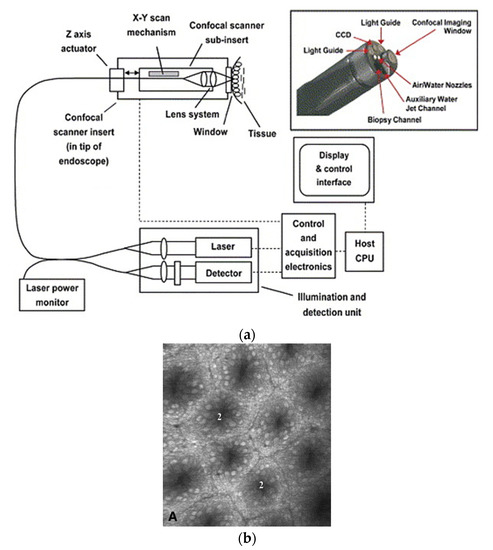
Figure 1. Fluorescence confocal imaging developed by Pentax: (a) schematic design of the micro-endoscope; (b) an en face image of rectal mucosa showing the crypt lumens (taken with the permission of [39]).
In most of the earlier endoscopes using CFBs to transport the light to the tissue surface, the beam is scanned using micromirrors placed at the proximal end of the device. In these so-called proximal scanners, the large-dimensioned scanning components can be separated from the distal end of the endoscopic device. Thus, it is possible to fabricate very compact-sized scanning devices. However, as the beam sweeps light across the CFB, a portion of the light enters through the cladding of the fibers as well, which results in poor contrast in the image. On the other hand, the scanning device is placed at the distal end of the endoscopic scanner to illuminate the light on the target sample in distal scanners. These single-fiber-based endoscopes require distal scanning to sweep the light across the target sample [40].
Among the distal scanners, it is possible to have two different configurations of devices based on the scanning direction [6]. In a side-view imaging device, the light from the fiber tip is deflected at a certain angle with the help of reflecting mirrors, or prisms. Such imaging devices provide circumferential images of the target surface, and 2-D cylindrical images can be obtained by moving the device along its axis using a drive motor or a rotational stage[41][42][43]. More recent side viewing imaging probes rely on the use of parabolic or cone-shaped mirrors at the distal tip. Such mirrors permit the incoming light from the fiber to be reflected in all directions, giving an omnidirectional side view. Such devices, called catadioptric probes, provide a panoramic field of view, obviating the need for rotation of the probe components [44]. However, in the forward-view imaging devices, the laser light is laterally scanned using special actuators and provides the image of the tissue surface at the front of the device [45]. The schematic diagram of a side viewing and forward viewing fiber-optic endoscope is shown in Figure 2 [6].
a)
b)
Figure 2. Schematic diagram: (a) side viewing probe; (b) forward viewing probe.
The features of the scanners based on these two kinds of imaging modalities are compared in Table 1 [6].
Table 1. Comparison between forward and side view scanners.
|
|
Forward View |
Side View |
|
Probe diameter |
>250 µm (proximal scanning) >1.65 mm (distal scanning) |
>250 µm (proximal scanning) >2.4 mm (distal scanning) |
|
Rigid length |
>9 mm |
>11 mm |
|
FOV |
50–400 µm |
~3–4 mm |
|
Image orientation |
en face |
Peripherical surface |
|
Advantages |
Can be used for image guidance to relocate and control the position of the medical devices, can directly image the extent of the malignancy and cancerous surface |
Can image the finer cavities of the body, gives information about the wall/section of tissue layer involved in the malignancy, higher field of view, less expensive |
|
Disadvantages |
Limited field of view, limitation of miniaturization limits the ability to image the narrower sections |
Difficult to guide the probe in the body due to lack of guidance |
In scanning fiber endoscopes, an optical fiber is fixed at a distance of a few millimeters from its distal end. The free end of the fiber acts as a cantilever beam, which is vibrated, using certain actuators described later in the paper, to illuminate the target tissue area. The backscattered reflected light is used to reconstruct the image of the area using certain image processing algorithms. These cantilevered optical fibers can be vibrated in resonance, or at a frequency different from their resonant frequency. The resonance actuation is used in cases where high-frequency operation and a high amplitude of the scanning fiber are required. The non-resonant scanners are preferred in cases when very different scan frequencies in two directions is a prerequisite. It is possible to avoid the drawbacks of both methods and keep the higher flexibility using a semi-resonant scanning mode.
4.1. Resonantly Actuated Scanners
Almost all the cantilevered-fiber optic endoscopes can be considered as cylindrical-shaped beams. The first resonant frequency (also called natural frequency) of a cylindrical-shaped cantilevered beam (where one side is rigidly blocked for any movement and the other end is free to move) is given by:
with E, ρ, R, and L being the Young’s modulus, density, radius, and length of the cantilever beam, respectively [46]. From this equation, the driving frequency in resonant scanners depends on the inherent properties and dimensions of the optical fiber acting as the cantilever beam. In nearly all such scanners, the fiber is a standard 125 µm diameter fiber. Thus, the resonant and driving frequencies can be adjusted by changing the length of the cantilevered section.
The main advantage of using the driving frequency equal to the resonant frequency consists in obtaining a higher tip displacement of the free end of the fiber, which results in high-resolution images (higher number of pixels in the FOV). It is possible to excite the cantilevered fiber using a variety of micro-actuators, such as piezoelectric [37][47][48][49], electromagnetic [50][51], electrothermal [52][53][54], shape memory alloys [55], or electroactive ionic polymer [56] actuators. The distal end of the fiber follows the mode shape shown in Figure 3. Each actuation method is better suited for the excitation frequency in certain ranges based on their working principle, which will be described in detail later in the paper. Various resonant scanners in the literature are compared in [57].
Figure 3. Deformation of the fiber tip excited at resonance.
4.2. Non-Resonantly Actuated Scanner
Some actuation methods such as electrothermal actuators are unable to generate motion at very high frequency. It is difficult to generate resonant scanners characterized with a low resonant frequency as they require long and slender beams, compromising their mechanical stability. In addition, the fiber tip displacement occurs symmetrically to the optical axis and is difficult to offset in resonant scanners. In such cases, the cantilevered optical fibers are excited at a frequency different from their resonant frequency. Even though there is less tip displacement for a given excitation power, it is possible to achieve beam scanning at low frequency and offset the center of the scan by adding a bias voltage [57].
Zhang et al. proposed a similar scanner where a 45-mm-long fiber was electrothermally actuated using a micro-electro-mechanical (MEMS) actuator operating at no more than 6 V [58]. A similar scanner was developed by Park et al., where a 40-mm-long fiber, used as an endoscopic OCT probe, was actuated using a 3 V power source [59]. Some researchers were able to develop cantilevered scanners working at a frequency not too far from their resonance frequency. In such semi-resonant scanners, the fiber tip provided an intermediate displacement, and no nonlinear whirling effects were present. Moon et al. developed an OCT probe where the cantilever scanner was excited at 63 Hz using a piezo-tube actuator [60].
A representative table highlighting the performance of three kinds of scanners described above is reported as Table 2 where the number of check marks indicates qualitatively the value of the parameter [6].
Table 2. Summary table for different scanners.
|
|
Resonant Scanner |
Semi-Resonant Scanner |
Non-Resonant Scanner |
|
Scan area |
✓✓✓ |
✓✓ |
✓ |
|
Power consumption |
✓ |
✓✓ |
✓✓✓ |
|
Operating frequency |
High |
Intermediate |
Low |
|
Advantages |
Large displacement amplitude, low power consumption |
Large scanning amplitude than non-resonant scanners, variable imaging field, stable working conditions |
Operable at very low frequencies, stable to small variations of operating conditions, image field is variable |
|
Disadvantages |
Offsetting the image field requires complex systems, Instability can lead to whirling motion |
Performance highly depending on the working frequency |
Small scanning amplitude, high power consumption |
Optical endoscopic imaging enabled the visualization of cellular and subcellular structures in real time, enabling early interventions and improved diagnostic yield from fewer biopsies. Moreover, the less invasive nature of the imaging device results in reduced tissue trauma, low risk of complications and operational costs, and fast recovery times. In forward viewing single fiber endoscopes, an optical fiber is rigidly fixed to an actuator’s substrate surface, leaving a few millimeters of free end at its distal end. Most often, this free end is vibrated at resonance to obtain a large tip displacement, which in these imaging devices is directly related to the resolution of the obtained image.
Various imaging applications, such as confocal endo-microscopy, OCT, photoacoustic imaging, etc., can be found using such endoscopes. Most of the devices mentioned in here find limited use in clinical application but are more in the transition from research to clinical phase. The only commercially available cantilever-based endoscopes for clinical use are those developed by Pentax [73] and Mauna Kea [32] Technologies.
The choice of an endoscopic device depends on the target imaging region, ease of use, and cost of the device. The cost of an endoscopic device comprises fabrication and operating cost. The operating costs mainly consist in decontamination and sterilization, which can be performed at high temperature such as autoclaving or hot air oven or at low temperature using chemical agents. The fabrication cost of an endoscope highly depends on the cost of the laser source, actuation, and detection mechanisms.


