1000/1000
Hot
Most Recent
 +1 point
A sensing material employed as a gas sensor will react with multiple gases, and for this reason, multiple sensing materials are employed in a network of gas sensors known as an electronic nose (eNose) system. By recording the response of this network of gas sensors, a signature which relates to the target analyte is detected, mitigating the issue of selectivity.
A significant proportion of agricultural fruits and vegetables originates from greenhouses, with increasing frequency and a steady rise in harvest land area for crops produced via greenhouse methods [1]. One main reason for the significance of greenhouse practices is that they offer the advantage of year-round production, enabling financial stability for the grower [2]. During the phases of plant growth and storage in agricultural greenhouse environments, there are various volatiles that can affect growth quality and prolong the shelf life of crops, including ethylene, carbon dioxide (CO2) hydrogen sulfide (H2S), ethanol and water vapor (humidity) [3][4][5].
Because of the key roles played by these small molecules, it is important to monitor them in plant growth environments such as greenhouses, as well as in storage and transport environments. Monitoring of such volatiles can be achieved with sensors that typically require the use of a sensing material. According to B. Eggins, there are three general classifications of sensors containing sensing materials: (1) chemical sensors where the analyte interacts with the sensing material via chemical or physical responses, (2) physical sensors which measure a physical change such as length, weight and temperature and (3) biosensors, which utilize a biosensing element to measure chemical substances [6]. The chemical sensing technologies (including electrochemical sensors) often work by transforming gas concentrations into an electrical signal such as current (amperometric sensors), potential (voltammetric), resistance (chemoresistive sensors) and frequency response (capacitive sensors, acoustic sensors and thermal magnetic) [7][8][9].
Some commonly reported classes of sensing materials are metal oxides [10][11], polymers (conducting and non-conducting) [12][13], and carbon nanotubes (including other allotropes of carbon such as graphene) [14][15]. There are also reports of multiple classes used simultaneously, like metal oxide/CNTs composites [16], polymer/graphene composites [17] and less commonly used materials like metal-organic frameworks (MOFs) [18] and ionic liquids [19]. This review discusses the above-mentioned types of sensing materials in terms of their method of application onto a sensor, physical properties once applied and mechanism of operation for detecting relevant agricultural analytes such as ethylene, CO2, ethanol, H2S and water vapor. It is observed that some of these sensing materials demonstrate sensitivity and selectivity to certain target analytes, while others are responsive to multiple analytes present in an agricultural greenhouse environment.
Many metal oxide materials have been developed and tested for the detection of ethylene. Li, Jin et al. reported the use of porous zinc oxide nanosheets (ZnO NS) as an ethylene sensing material to determine fruit ripeness [20]. Another notable metal oxide; commercially available tin oxide, SnO2 nanoparticles, reported by Agarwal and colleagues, show the capability of detecting ethylene at 20 ppm levels with CO2, SO2, NH3, NO2, and H2S, NH as an interfering gas at concentrations ranging from 1000–3000 ppm at room temperature [11]. In regards to carbon allotropes, Swager et al. used single-walled carbon nanotubes (SWCNTs) functionalized with 4-pyridyl moieties as a sensing material in monitoring the senescence in red carnation via the detection of trace levels of ethylene gas [21]. In a different class of viable materials, the use of commercially available ionic liquids (ILs), such as 1-butyl-3-methylimidazolium bis(trifluoromethyl sulfonyl)imide ([BMIM][NTf2]), is reported by Zevenbergen et al.
A wide variety of metal oxide sensing materials have been reported for their use in CO2 detection. One such sensing material under this class is reported by Karthik et al., who developed a Zinc oxide (ZnO) sensing material, synthesized by the thermal decomposition of precursors such as zinc acetate and zinc nitrate [22]. Another notable metal oxide for use in CO2 detection is cerium oxide (CeO2) nanospheres [23]. Karthik et al. coated a g-C3N4 nanosheet with TiO2, forming a hybrid 2D sensing material for the purposes of CO2 detection [24].
Baltrusaitis et al. reported a material under the polymer class; methylated poly(ethylene) imine (mPEI) for CO2 detection, synthesized by previously reported work [13]. This polymer is also sensitive to sulfur dioxide (SO2) detection, to which the material shows a lower sensory response. Among the viable ionic liquid sensing materials is 1-ethyl-3-methylimidazolium bis (trifluoromethyl-sulfonyl)-imide (EMIM[NTf2]), which was investigated by Bhide et al. [25]. Wei et al. reported a rather exotic sensing material, which was a functionalized pillar[5]arene/bipyridine salt for the detection of CO2 at a detection limit of 2.2 ppm [26].
Under the metal oxide material class, Li et al. used indium oxide (In2O3) nano-cubes for sensing H2S at room 25 °C and 100 °C [27]. Synthesis of this material involved a cetyltrimethyl ammonium bromide (CTAB)-assisted solvothermal and subsequent calcination process. This material has a very impressive 5 ppb limit of detection and interestingly, selectivity between NO2 (also able to detect) and H2S sensing can be tuned using temperature (25 °C versus 100 °C). A viable material under the polymer material class—polyaniline/metal chloride nanofiber composites as sensing materials for H2S detection—was reported by Virji et al. [28]. Among the carbon allotrope material class, Asad et al. reported single-walled carbon nanotubes (SWCNTs) modified with copper nanoparticles for H2S detection [29].
Among the metal oxide class, palladium/titanium oxide (Pd/TiO2) nanorod arrays and tin sulfide (SnS) nanoflakes were reported by Dutta [30] and Afsar [31]. The Pd/TiO2 nanorod arrays are also sensitive to 2-propanol and able to detect down to 1 ppm of theses alcohol vapors. Within the polymer material class, Yoon et al. used poly(styrene-co-allyl alcohol) (PSAA) as a sensing material (other materials also shown) in a wireless sensor to detect ethanol, which proved to be cross sensitive to acetone and ethylene [32]. Among ionic liquids, Xu et al. reported a viable material for the detection of ethanol are alkyl-imidazolium halide [33], which can be synthesized using simple solution synthetic methods, or can be procured commercially.
Within the metal oxide material glass, Zhang et al. reported a graphene oxide/polymer composite for humidity detection [10]. Shifting focus to the polymer sensing materials, Zhao et al. reported MWCNTs functionalized with poly-L-lysin (PLL) to be a viable sensing material for humidity detection [34]. Qi et al. demonstrated a material under the carbon allotrope material class known as chitosan-wrapped multi-walled carbon nanotubes (MWCNTs-CS) for detecting humidity [15]. Duan et al. reported Halloysite nanotubes as a sensing material for humidity which has a dynamic range of 0–91.5% RH [35]. For use in fibre-optic sensing applications, a wide range of sensing materials is available for humidity detection. This group of gas sensors employs several techniques, including fibre grating, evanescent wave monitoring, interferometric approach and absorption measurements, as well as hybrid sensors [36][37][38][39].
One of the challenges in sensor development for agricultural monitoring is to apply the developed sensing material to the active area of a sensor; this is often referred to as material deposition. In addition, since there are different mechanisms of operation for gas sensors due to their different structures, including capacitive and piezoelectric-based, QCM, chemiresistive and fibre-optic gas sensors, particular deposition techniques should be utilized to improve sensors’ performance in static and dynamic operations. Therefore, the sensor’s mechanism of operation, along with desired sensing material thickness and active area, which agree to the optimum sensor’s response point, can define the potential deposition technique. The most common deposition method observed using all the sensing materials mentioned in previous sections, is drop-coating. This technique is mostly used in chemiresistive gas sensors; obtaining a layer of few nanometers sensing material is not required [23][24]. Other common methods that are also suitable and utilized to deposit the aforementioned sensing materials include spin-coating, dip-coating, spraying, electro-spinning, and inkjet printing, as shown in Table 1. Gas sensors such as capacitive-based structures, which have a thick layer of sensing material, can have a negative impact on their operation benefit from the inkjet printing technique [40].
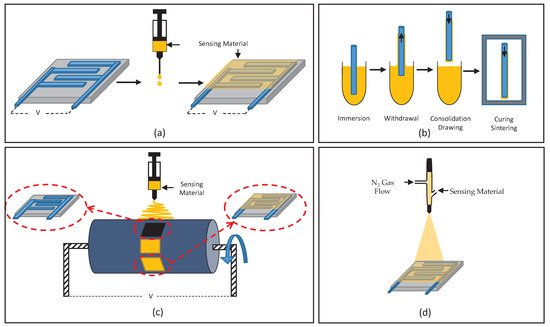
Figure 1. Schematic illustration of deposition methods: (a) drop-coating, (b) dip-coating, (c) electro-spinning and (d) spraying.
Table 1. Material deposition methods, sensing technologies, sensor performance parameters and operating temperatures with various sensing materials and target analytes in gas phase.
| Sensing Material |
Target Analyte |
Sensing Technology |
Deposition Method |
Material Thickness |
Dynamic Range & Limit of Detection |
Recovery Time |
Operating Temperature |
Long-Term Stability |
Sensitivity (Output/Input) |
Refs. |
|---|---|---|---|---|---|---|---|---|---|---|
| BMIM-NTf22////////// | Ethylene | Amperometric | Drop-coating | 63 µm | 760 ppb–10 ppm | - | 22 °C | - | 51 pA/ppm | [19] |
| Porous ZnO NS | Ethylene | Chemiresistive | Dip-coating | 10 nm | 5–2000 ppm | 20 s | 350–500 °C | 30 days | 0.6 µA/ppm | [20] |
| LaFeO3 | Ethylene | Chemiresistive | Screen printing | 37–38.3 µm | 25–5000 ppm | ~1 s | 20–200 °C | - | 0.4Ω/ppm | [41][42] |
| SWCNTs | Ethylene | Chemiresistive | - | 1 µL | 0.5–50 ppm | - | 4 °C | 16 days | 1.2%R/ppm | [21] |
| SnO2 nanoparticles | Ethylene | Chemicapacitive | Dip-coating/Sputtering | 1300 nm | 20–100 ppm | ~10 s | 22 °C | - | 0.0531 pF/ppm | [11] |
| PtTiO2 | Ethylene | Magnetoelastic | Dip-Coating | 31–155 nm | 0.5–50 ppm | - | 19 °C | - | 8.5 Hz/ppm | [43] |
| ZnO | CO22 | Chemiresistive | Spray pyrolysis | 8.3 nm | 50–1000 ppm | 100 s | 300 °C | - | 800 Ω/ppmΩ | [22] |
| PEDOT PSS/graphene | CO22 2 |
Chemiresistive | Calibrated spreader | 10 µm | 4.7–4500 ppm | - | 35–65 °C | - | 0.004–0.0047%R/%RH | [44] |
| TIO2 coated g-C3N4 NS | CO22 | Chemiresistive | Drop-coating | 30 nm | 100–2500 ppm | 35 s | 22 °C | 60 days | 406 µΩ/ppmμ | [24] |
| CeO2 | CO22 | Chemiresistive | Drop-coating | 170–210 nm diam. | 150–2400 ppm | ~1 s | 100–250 °C | - | 4.88 kΩ/ppm | [23] |
| EMIM[NTF2] | CO22 | Chemicapacitive | Dip-coating | <1 µm | 50,000–1,000,000 ppm | 38.5 s | Room temperature | - | 29 pF/ppm | [25] |
| HPTS | CO22 | Fibre-Optic | Dip-coating | >1 µm | 300–300,000 ppm | 50–100 s | 22 °C | - | 0.00055 a.u./ppm | [45] |
| mPEI | CO22 | Resonator | Spin coating | - | 0.011% | - | - | - | 8 Hz/ppm | [13] |
| CuO,Fe2O32 | H2S | Amperometric | - | - | 10ppm | - | −15 °C–65 °C | - | 700 µA/ppm | [46] |
| CNTs/SnO2/CuO | H2S | Chemiresistive | Spin-coating | >6 nm | 10–80 ppm | 10 min | 25 °C | - | 4.41Ω/ppm | [16] |
| SnO2 nanofibres | H2S | Chemiresistive | Electro-spinning | 150 nm diam. | 0.1–1 ppm | 230 s | 200–350 °C | - | 970kΩ/ppm | [47] |
| Zn2SnO4 NS | H2S | Chemiresistive | Dip-coating | 100 nm | 5–1000 ppb | 1300 s | 133–170 °C | 60 days | 1.08MΩ/ppb | [48] |
| In2O3 | H2S | Chemiresistive | Dip-coating | 100 um | 5 ppb | 5 min | 25–100 °C | 30 days | 13.02 kΩ/ppm | [27] |
| WO3, PPy | H2S | Chemiresistive | - | 50–100 nm | 200 ppm | >1 day | 90 °C | - | 490 µV/ppm | [49] |
| SWCNTs | H2S | Chemiresistive | Spin-coating | 1–2 nm diam. | 5 ppm–150 ppm | 10–15 s | 20 °C | - | 0.47%R/ppm | [29] |
| ZnO Nanowires | Ethanol | Chemiresistive | Spin-coating | 25 nm diam. | 1–200 ppm | 120 s | 300 °C | - | 644Ω/ppm | [50] |
| SnS | Ethanol | Chemiresistive | - | - | 10 ppm | 9 s | 200 °C | 6 weeks | 0.27–13.5%R/ppm | [31] |
| Pd/TiO2 | Ethanol | Chemicapacitive | Nanorod growth | 710–750 nm | 1–100 ppm | 2.4–3.8 s | 100 °C | - | 7.5%C/ppm | [30] |
| SiO2/Si NW | Ethanol | MGFET | vapor-liquid-sold growth | 16 nm diam. | 26–2000 ppm | 4 min | 60 °C | - | 16–40 pA/ppm | [51][52] |
| PSAA | Ethanol | Resonator | Drop-coating | 19.9 nm | 13.3 ppm | 20 min | 24 °C | - | 1.5 Hz/ppm | [53] |
| CuO particles | Water Vapor | Chemiresistive | Drop-coating | 140 µm | 33–90%RH | - | 22 °C | - | 0.5–30kΩ/%RH | [54] |
| WS2 NS | Water Vapor | Chemiresistive | Drop-coating | 6 nm | 8–85%RH | 30–140 s | - | several weeks | 580 MΩ/%RH M | [55] |
| MWCNTs-CS | Water Vapor | Chemiresistive | - | - | 11–95%RH | - | Room temperature | - | 2.4 mΩ/%RH | [34] |
| MWCNTs-PLL | Water Vapor | Chemiresistive | Drop-coating | - | 0–91.5%RH | - | Room temperature | - | 3.78kΩ/%RH | [34] |
| MoS2/ND | Water Vapor | Chemicapacitive | - | - | 11–97%RH | - | Room temperature | - | 6.5 nF/%RH | [56] |
| SPEEK | Water Vapor | Impedance-based | Drop-coating | 20 µm | 11–95%RH | 130 s | 22 °C | 30 days | 12-120MΩ/%RH | [57] |
| TiO2 Nanowires | Water Vapor | Impedance-based | Dip-coating | 40–50 nm | 12–97%RH | <2 min | 17–35 °C | 250 days | 144kΩ/%RH | [58] |
| Silica/di-ureasil FBG | Water Vapor | Fibre-Optic | Dip-coating | 450–591 µm | 5–95%RH | - | 5–40 °C | 1 year | 1.25–7.14 pm/%RH | [59] |
| PI | Water Vapor | Fibre-Optic | Dip-coating | 450–591 µm | 5-95%RH | - | −15–20 °C | - | 1.85–2.25 pm/%RH | [60] |
| Al2O3+/PSS- nano-film | Water Vapor | Fibre-Optic | ESA | 84nm | 22–39%RH | - | 24.5 °C | - | 1.43 nm/%RH | [61] |
| SiO2 | Water Vapor | Fibre-Optic | ESA | 300 nm | 20–80%RH | 150ms | 10–40 °C | - | 67.33–451.78 pm/%RH | [62] |
| CaCl2 | Water Vapor | Fibre-Optic | - | 3 µm | 55–95%RH | - | 30 °C | - | 1.36 nm/%RH | [63] |
| CoCl2 | Water Vapor | Fibre-Optic | Drop-coating | 10 µm | 50–95%RH | ~40 s | 25 °C | - | 67–200 pm/%RH | [64] |
| HEC/PVDF | Water Vapor | Fibre-Optic | Dip-impregnation | - | 40–90%RH | - | 28 °C | - | 0.196 dB/%RH | [65] |
| PAA Nanowires | Water Vapor | Fibre-Optic | Electrospinning | - | 30–95%RH | 210 ms | 25 °C | - | 0.01 dB/%RH | [66] |
| ZnO Nanorods | Water Vapor | Fibre-Optic | Dip-coating | 2.5 µm | 10–95%RH | - | 25 °C | - | 0.0007–0.0057%P/%RH | [67] |
| PVA | Water Vapor | Fibre-Optic | Dip-coating | 8 µm | 20–95%RH | 500 ms | 20–100 °C | 7 days | 25–980 pm/%RH | [68][69][70][71] |
| PEO | Water Vapor | Fibre-Optic | Dip-coating | - | 85–90%RH | ~1 s | 22 °C | - | 1.17 dB/%RH | [72] |
| Silica/methylene blue | Water Vapor | Fibre-Optic | Dip-coating | - | 1.1-4.1%RH | <30 s | 18 °C | - | 0.0087 a.u./%RH | [73] |
| Ag-Polyaniline | Water Vapor | Fibre-Optic | Dip-coating | 15–30 nm diam. | 5-95%RH | 90s | 25–30 °C | - | 10–29 mV/%RH | [74] |
| PGA/poly-lysine | Water Vapor | Fibre-Optic | Soaked in polymer | 1 µm | 50–92.9%RH | 5.8 s | - | - | 0.01 dBm/%RH | [75] |
| ZnO | Water Vapor | Fibre-Optic | Dip/Spin-coating | 70–80 nm diam. | 5–50%RH | 35 s | 22 °C | - | 0.45%dB/%RH | [76] |
| Co/Polyaniline | Water Vapor | Fibre-Optic | Dip-coating | 10.4 µm | 20–92%RH | 1 min | 30 °C | - | 0.024–3.406 mV/%RH | [77] |
| Gelatin | Water Vapor | Fibre-Optic | Dip-coating | 80 nm | 9–94%RH | ~50 s | 22 °C | - | 0.167 dBm/%RH | [78] |
| Chitosan | Water Vapor | Fibre-Optic | Dip-coating | - | 20–80%RH | - | 25 °C | - | 81 pm/%RH | [79] |
As new sensing materials and technologies continue to be developed for use in greenhouse environments, it will be essential to demonstrate their operation in representative environments that explore long-term stability and cross-sensitivity under realistic conditions. The rapid advances in sensing materials, morphology, and structure, as well as transduction mechanisms are expected to address current limitations in performance and are expected to enable miniaturized, low-power sensors capable of achieving wireless, distributed sensor networks for the continuous monitoring of agriculture environments. Further experimentation on the listed sensing materials should be implemented, recording the sensitivity of each material to their respective analyte over a long period of time to validate the usefulness of each material for greenhouse applications. Furthermore, the material’s solubility in water and sensitivity to elevated RH can help determine where the sensor ought to be located within the greenhouse.


