Compliant continuum robots (CCRs) are usually made of elastic materials, including nitinol alloy (NiTi), silicone, rubberand polyamide, etc. They are designed to be slender, i.e., low diameter to length ratio. CCRs have been widely employed in a constraint environment to manipulate tasks, such as minimally invasive cardiac surgery, orthopaedic surgery, endoscopic surgery, bariatric surgeryand the inspection of gas turbine engines, in-situ aero-engine maintenance works.
1. Introduction
CCRs have been widely employed in a constraint environment to manipulate tasks, such as minimally invasive cardiac surgery [1], orthopaedic surgery [2][3][4], endoscopic surgery [5], bariatric surgery [6] and the inspection of gas turbine engines [7], in-situ aero-engine maintenance works [8][9][10][11]. Researchers usually classify CCRs in two ways, one is the drive system classification, including tendon-driven robots, cable-driven robots, pneumatic robots, shape-memory-alloy robots. In this paper, we classify the CCRs into two groups, including semi-soft continuum robots and soft continuum robots. sometimes rigid disks or rods are added to increase rigidity [12].
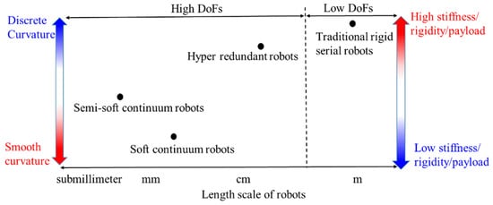
Traditional serial robots consist of rigid links and rigid joints. The comparison between continuum robots and rigid serial robots is shown in Figure 1, including the curvature of a robot’s shape, size, stiffness and degrees of freedom (DoFs). Semi-soft continuum robots have a minimal scale compared with others; recently a magnetic soft submillimetre scale continuum robot blurs the line between the semi-soft continuum robot and the soft continuum robot, as the magnetic fluid can turn into an elastic solid under a magnetic field [13]. Remaining a high stiffness and a smooth curvature are the aims for designing a continuum robot.
Figure 1. The comparison between CCRs and rigid serial robots.
2. Trends and Classifications of CCRs
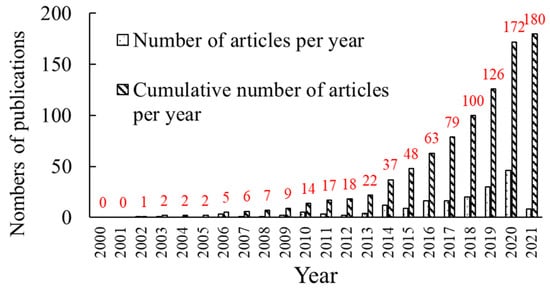
The development of CCRs is shown in
Figure 2 from 2000 to 2021. The prototype of CCR was introduced in 2000. It consists of elastic springs, rigid disks and rotational joints, and it is driven by cables
[14]. During the following years, there was little research about CCRs from 2002 to 2013, but since 2014, there was a rapid increase in research of CCRs, as shown in
Figure 2, and the cumulative results can also be seen.
Figure 2. The numbers of publications about CCRs per year.
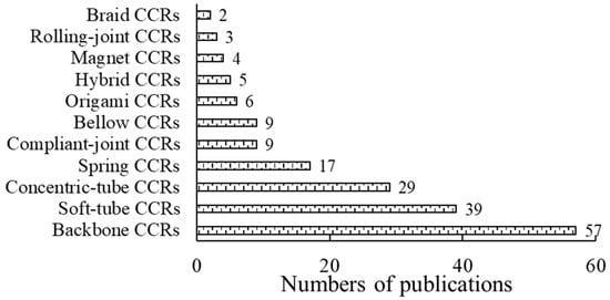
CCRs are divided into eleven types according to basic transmission units, as shown in Figure 3. Soft-tube CCRs belong to soft CCRs, while others belong to semi-soft CCRs. Backbone, soft-tube, concentric-tube and spring CCRs account for a large proportion, followed by compliant-joint, bellow, origami and hybrid CCRs, and the rest of the types are analysed by researchers recently. Their characteristics and problems are summarised in Table 1, which are detailed in the following Sections.
Figure 3. The numbers of publications about different CCRs from the literature review.
Table 1. Descriptions of CCRs.
| |
|
Descriptions |
| Characteristics |
basic transmission units |
Basic motion units of CCRs. |
| drive systems |
Actuation force/moment systems, such as the pull-push force, the pneumatic pressure, the hydric pressure and the magnetic force, etc. |
| stiffness |
Stiffness is the rigidity of a CCR. Including variable stiffness and constant stiffness. |
| sensing systems |
The accuracy of motions increases with the feedbacks of the sensing systems, including external sensors and intrinsic sensing. |
| Problems |
frictions |
Frictions between component units, such as frictions between cable and disk holes. |
| buckling |
The stiffness suddenly decreases to quasi-zero, when a compressing load acts the CCR. |
| singularity |
The ill Jacobian matrices between the inputs and outputs. |
| twisting |
Both torques generated by the CCR weight and the payload influence the tip position. |
3. Different Basic Transmission Units and Drive Systems
In this section, the basic transmission units and drive systems are described. The combination of different basic transmission units to form a CCR is called a hybrid CCR, which is also illustrated at the end of this section.
3.1. Basic Transmission Units
3.1.1. Backbone CCRs
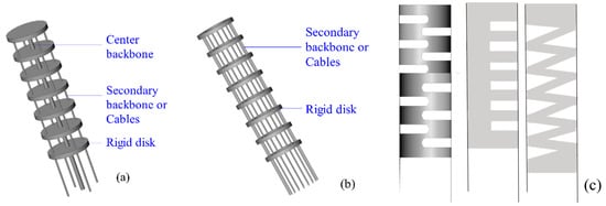
The backbone CCRs are shown in
Figure 4. Most backbones are made of Nickel-Titanium (NiTi) and polypropylene
[1]. A centre backbone, secondary backbones (or cables) and several rigid disks are commonly used to form a backbone CCR, shown in
Figure 4a
[15][16][5][17][18][19][20][21][22][23][24][25][26][27][28][29][30][31][32][33]. The central backbone is connected to all the disks. The secondary backbones (or cables) are only connected to the end disk and freely slide in the disk holes for driving the CCR. A backbone CCR also can consist of multi-secondary backbones without a centre backbone, shown in
Figure 4b
[27], which is wearable and used for shoulder recovery. The centre backbone can be an elastic tube
[32], an elastic notched tube
[34], a half elastic notched tube
[35], or an elastic V-shape tube
[36][37], shown in
Figure 4c. The last three tubes can be employed as backbone CCRs without rigid disks.
Figure 4. Backbone CCRs: (
a) A robot with a centre backbone
[15][38][39][40], (
b) a robot without a central backbone
[27] and (
c) notched backbones
[37].
The metrics of the backbone are as follows. The distance between two disks can be evenly distributed. The continuous configuration of backbones benefits kinematics modelling. If the backbone has multi-segments, all the endpoints of different segments can be on the same curve, which is easy to correct the curve closing to desired one
[19]. The rigidity of the backbone CCR can be adjusted by two methods, including increasing the number of secondary backbones
[27] and inserting a rod moving in the centre backbone tube
[6][35][41]. The effective bending section of the backbone CCR is controllable by regulating the inserting length of the rod. However, the torsional rigidity of the backbone CCRs is necessary to be enhanced to avoid a low payload and a small stiffness control range
[42].
3.1.2. Soft-Tube CCRs
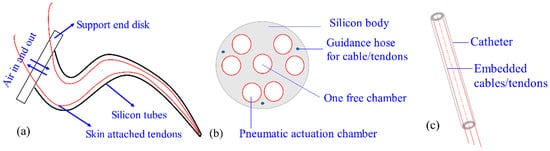
Soft-tube CCRs are the softest type among the CCRs, shown in
Figure 5. The soft-tube CCR in
Figure 5a
[43][44] has a silicone tube, which is actuated by pneumatic, shape memory alloy and multi-embedded tendons. The soft-tube CCR in
Figure 5b
[45] has a silicone-backbone shape, consisting of a free chamber, six actuation chambers and three driving cables. Its stiffness can be regulated by the pneumatic pressure. The catheter has a sub-millimetre size, shown in
Figure 5c, and it is usually made of urethane rubber
[46] and polymer
[47]. The stiffness of the soft-tube CCRs in
Figure 5a,c is less rigid than that of
Figure 5b. On the other hand, soft-tube CCRs can be actuated by driving cable, pneumatic champers, shape memory alloy, or electro-polymer. The first two drive systems have higher ratios of power to weight than others. A soft-tube CCR always requires a compliant actuator with a high ratio of power to weight than other CCRs, due to the hyper-redundant DOF
[48], so cables and pneumatic champers are commonly used in soft-tube CCR.
Figure 5. Soft-tube CCRs: (
a) A silicone-tube CCR
[43][44], (
b) the cross section of another silicone-backbone CCR
[45] and (
c) a catheter CCR
[46][47][49][50][51][52].
Soft-tube CCRs have a large elastic deformation and hyper-redundant DoFs. However, their higher compliance reduces the rigidity and positioning accuracy significantly
[53]. The lack of rigidity of soft material can result in buckling and strong nonlinearities of the kinematic model. In 2018, Li et al. tried to avoid buckling by optimising controlling models
[54]. Soft skin is easy to be torn and punctured, so Wang et al. combined different types of fibres into the silicone to improve their strength and durability
[55].
3.1.3. Concentric-Tube CCRs
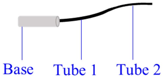
Concentric tubes are first introduced by Webster et al.
[56]. Most tubes are made of superelastic Nitinol, and some of them are made of polyether block amide
[57]. They are pre-curved and superelastic, as shown in
Figure 6. The concentric tubes are inserted inside each other, and they are translated and rotated axially about the concentric axis at the base by tube interactions
[58][59]. In this way, the length and curve of the concentric-tube CCR are varied.
Figure 6. A two-tube concentric-tube CCR
[60][61].
The main advantage of concentric-tube CCRs is the sub-millimetre body with enough stiffness, such as a 0.8 mm-diameter tube
[62], which leads to a lower infection possibility during the surgery. However, the kinematic analysis is difficult for the special actuation. If the stiffness of these tubes is not comparable, or elastic energy storage occurs in high tube curvatures, the rapid snapping problem may happen
[62]. The snaping problem means the CCR snaps quickly from one configuration to another with the energy released suddenly
[63]. The concentric-tube CCR should be snap-free to avoid serious harm to patients
[64]. In addition, they have limited variations of resultant curvatures as the tubes are pre-curved, so the minimum requirement for the concentric-tube CCRs is to extend into the body smoothly
[58][65][66]. The frictions between tubes should not be neglected
[64][67][68].
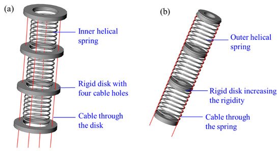
3.1.4. Spring CCRs
Springs can be used in two ways to form a spring CCR, including inner helical springs and outer helical springs, as shown in
Figure 7. An inner helical spring can be employed as a central backbone
[69][70][71][72][73][74][75][76] to evenly distribute disks. An outer spring can be multi-disks to confine cables
[77][78][79]. Most spring CCRs are made of steel or NiTi, and they are actuated by cables.
Figure 7. Spring CCRs formed with: (
a) An inner helical spring
[70][80] and (
b) an outer helical spring
[76].
A helical spring has a linear relationship between force and displacement, i.e., an unchanged spring constant, which simplifies the kinematic analysis significantly
[70]. The workspace of helical spring CCRs can be expanded by applying a high spring constant. The unwanted extension, uncontrolled compression and singularity can be avoided by applying a low spring constant. The combinations of high and low spring constants can improve torsional rigidity
[70]. In addition, spring can also be a buffer to reduce the effects from the environment
[11].
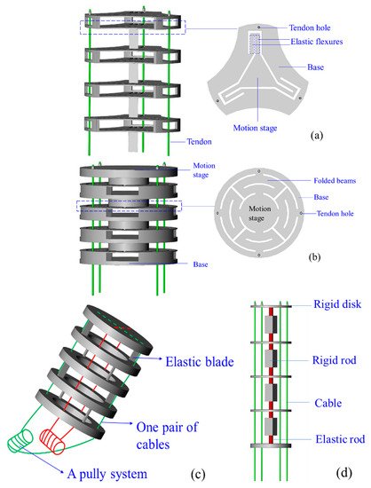
3.1.5. Compliant-Joint CCRs
Compliant joints are designed with elastic blades, wire beams, and rigid disks. Blades and wire beams are commonly made of NiTi
[12] and polyethylene
[81]. Most disks are made of acrylonitrile butadiene styrene (ABS) material for lightweight, and they can constrain cables
[82] and increase the rigidity of CCRs
[79]. The geometric difference between blade and wire beams is the ratio of width to thickness. The ratio of a blade is larger than 10, and that of a wire beam is equal to 1.
Figure 8 shows the compliant joints, and they can be arranged in series to form a CCR. The compliant-joint CCRs are actuated by cables or backbones, and their curves are varied with the rotations and translations of the elastic blades or wire beams.
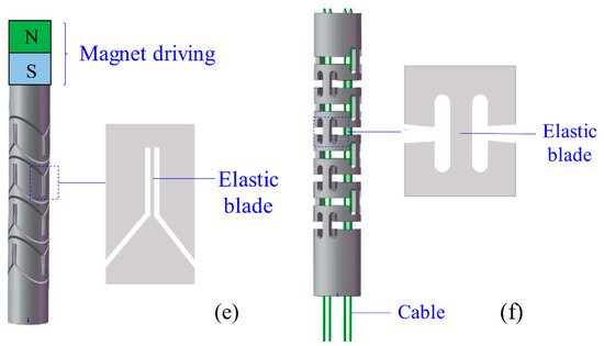
Figure 8. Different compliant joints for the compliant-joint CCRs: (
a) A planar spring
[83], (
b) a planar spring with minimised parasitic motions
[84], (
c) multi-two-pivots compliant joints
[12], (
d) a compliant joint with two short elastic beams
[85], (
e) multi compliant joints with elastic blades
[86] and (
f) multi compliant joints with round-corner blades
[87].
Compared with the rotational symmetric planar spring of Qi et al.
[83], shown in
Figure 8a, the planar spring of Awtar et al.
[84] is a mirror-symmetric consisting of eight folded beams, which decreases parasitic motions significantly, shown in
Figure 8b. Dong et al. presented two types of compliant joint with elastic blades
[12] and short beams
[85], shown in
Figure 8c,d, respectively. The compliant-joint CCR formed with the multi-elastic blades can anti twisting compared with the CCR formed with two short beams. Thomas et al.
[86] and Zhang et al.
[87] designed compliant-joint CCRs with elastic blades, shown in
Figure 8e,f, respectively.
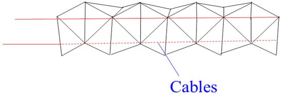
3.1.6. Bellow CCRs
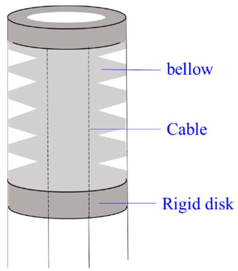
Figure 9 shows a segment of a bellow CCR. Most bellow CCRs are made of polyamide, and they are actuated by pneumatic or hydraulic pressure with a cables-driven assistant. They can expand or elongate with variable curves as expected by pulling or pushing cables when bellows are filled with air.
Figure 9. A bellow CCR with cable-driven system
[88].
Bellow CCRs are lightweight with a smooth curvature. Another advantage of the bellow is to be employed as an anti-buckling support structure if they are made of NiTi material
[31], as NiTi is more rigid than polyamide with enough elasticity. However, bellow CCRs are sometimes unreliable for the non-stationarities during pneumatic or hydraulic actuation
[89]. The rigidity of polyamide bellow CCRs is relatively low, so the disks are usually added around the bellow to increase the rigidity
[90].
3.1.7. Origami CCRs
Mirror folds, water bomb, folds and reverse folds are basic folds for origami continuum robots. Origami CCRs are made of photopolymer resin or sticky polyamide film
[91], which are driven by cables
[92][93] as shown in
Figure 10. Each crease of the origami can be regarded as a 360-degree revolute joint, so Origami CCR has two types of body shapes, including a 2D shape and a 3D shape. They can go through a constrained environment in a smaller 2D shape and morph into a 3D device. If they are applied in minimally invasive surgery, the possibility of infection decreases.
Figure 10. An origami CCR with a cable-driven system
[92][93].
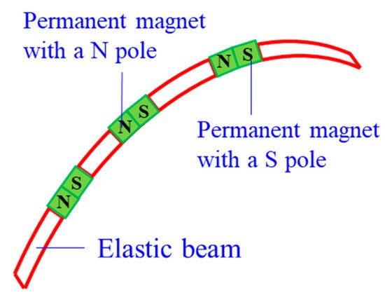
3.1.8. Magnet CCRs
Magnetic CCRs are another type of sub-millimetre continuum robots, including permanent-magnet-joint CCRs
[94] and magnetic-fluid CCRs
[13]. Permanent magnets and magnetic fluids are controlled in the magnet field without any actuation wires. A permanent-magnet-joint CCR is shown in
Figure 11. The elastic beams are actuated by the interactions of N and S poles. As for magnetic-fluid CCRs, the magnitude of the magnet field affects the viscosity of the magnetic fluid, and the viscosity can be close to the solid viscosity with the increase of the magnitude. Magnet CCRs can also be mounted on medical devices and serving as a guide.
Figure 11. A permanent-magnet CCR
[94].
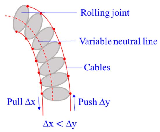
3.1.9. Rolling-Joint CCRs
Rolling-joint CCRs are special for a variable neutral line of the robot, as shown in
Figure 12. Most rolling joints are made of ABS material to reduce weight. They are actuated by non-circular spur gears
[95] as the asymmetric arrangement of rolling joints (∆
x ≠ ∆
y), and the nonlinear actuating relationship of force and tension is complex to model
[96]. Compared with the friction between cables and disk holes, the friction between rolling joints should not be neglected.
Figure 12. A rolling-joint CCR with a cable-driven system
[96].
3.1.10. Braid CCRs
Braid CCRs are inspired by human muscles, which are braided with non-extensible, but flexible fibres in helical arrays. They can extend, contract and bend by actuating embedded radial and longitudinal tendons
[97], and they can also be actuated by the pneumatic artificial muscles
[98]. They can vary stiffness by antagonistically actuating actuators or increasing the pneumatic pressure. The size of this robot is not miniature, ranging from 10 cm to 27 cm.
3.1.11. Hybrid CCRs
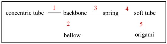
Hybrid CCRs are designed for complementing the shortcomings of a basic unit with the merits of another. Figure 13 shows the eight types of combinations of the different basic units. Most hybrid CCRs consist of a backbone due to the continuous shape.
Figure 13. Combinations of different basic transmission units for the hybrid CCRs.
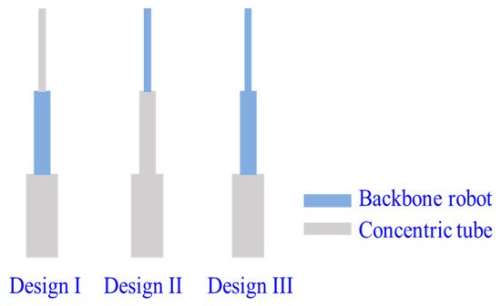
Concentric-tube CCRs can be submillimetre, but they have limited resultant curves and snapping problems. Backbone CCRs are flexible, but the coupling between different segments of a backbone CCR is still a challenge. Wu et al.
[99] introduced a backbone-concentric-tube CCRs, whose dexterity is improved and the size is submillimetre. They analysed three combinations of the backbone-concentric-tube robot, as shown in
Figure 14. The results show that design II can avoid snapping and coupling of different segments compared with others.
Figure 14. Three designs of the backbone-concentric-tube CCRs
[99].
The nickel bellow has much higher rigidity than a polyamide bellow. The torsional rigidity of the backbone CCRs is relatively low. Xu et al. introduced a backbone-bellow CCR, whose nickel bellows wrap outside of the backbones
[31]. The torsional rigidity of the backbone CCR is enhanced more than four times when a nickel bellow is integrated, and the bending capabilities are not compromised.
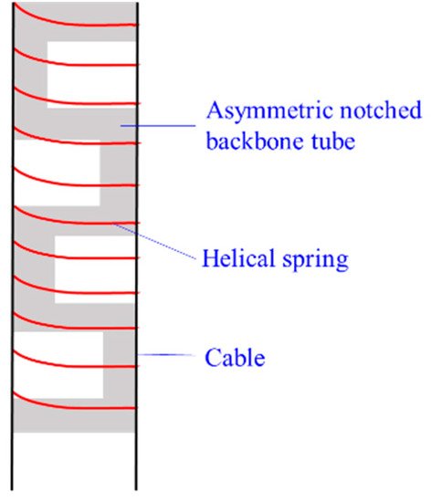
Sharp bending is a challenge for concentric-tube CCRs. To maintain the miniature size and enable sharp bending, Francis et al.
[77] introduced a new asymmetric notched backbone-spring CCR, where a helical spring wraps outside of a notched backbone tube, as shown in
Figure 15. The helical spring is also used to confine the cables.
Figure 15. The design of the notched backbone-spring CCRs
[77].
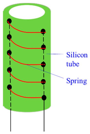
Xing et al.
[100] designed a soft tube-spring CCR, which is super flexible and driven by cables. The spring is employed for confining cables. It is different from the above hybrid CCRs as the spring is in the silicone tube, as shown in
Figure 16.
Figure 16. The soft tube-spring CCR
[100].
Li et al. presented an origami gripper with soft silicone skin
[101]. This gripper is actuated by pneumatic, which can catch different things without shape requirements. This is not a CCR, but it is promising to similarly design a silicone-origami CCR in the future.
3.2. Drive Systems
Drive systems depend on the basic transmission units of CCRs significantly. Most semi-soft CCRs can be actuated by backbones or cables. The main difference between the backbone-driven and the cable-driven system is as follows. The minimal number of backbones to bend a CCR in any direction is two, but that of cables is three. The reason is a backbone can be compressed and extended, while a cable cannot be compressed. The third actuating backbone or the fourth cable can be employed as the actuation redundancy
[102]. A pully system usually actuates one pair of cables, which motivates Dong et al. to present a spooling system (i.e., twin pully systems) to minimise the size of the actuation system significantly
[103]. In addition, cable tension is required to be calculated for avoiding cable slack
[12], and the backbone-driven system does not have this problem.
Most soft CCRs are actuated by pneumatic and hydraulic pressure, which can modify the length of chambers by varying the air or fluid pressure in the chambers
[90]. Cable-driven assistance is usually used for soft CCRs. Shape memory alloy (SMA) and electroactive polymer (EAP) are also used in CCRs. Shape memory alloy can change into a certain shape when the temperature reaches the critical temperature
[73][104][105]. Electroactive polymer is a special material that contracts and extends by soft embedded compliant electrodes
[106][107]. The advantages and disadvantages of different drive systems are summarised in
Table 2.
Table 2. Summary of different drive systems.
| Drive Systems |
Advantages |
Disadvantages |
| Cable/tendon |
Exert large force; easy control; large ratio of power to weight. |
Cable slack; cable coupling; friction between cables and disks. |
| Backbone |
Remote actuation; fewer actuation wires; reduce buckling. |
Backlash; frictions between actuation lines and conduits; extension and compression of actuating backbones. |
| Pneumatic |
Exert large force; variable stiffness by regulating air pressure; large ratio of power to weight. |
Strong nonlinearities of a kinematic model; not safe enough if the air leak. |
| Hydraulic |
Exert large force. |
The extra weight of fluid; failure of the hydraulic power supply. |
| Magnet |
No surface contact; lightweight;
Tether-free actuation; sub-millimetre scale. |
Complex electromagnets control. |
| SMA |
Certain shape curvature. |
Need efficient cooling system; sensitive to environment temperature; slow response speed. |
| EPA |
Lightweight; small scale. |
Low actuation pressure; required high input voltage; limited range motion. |
 +1 point