1000/1000
Hot
Most Recent
 +1 point
Analysis of existing studies has shown that under certain geological conditions it is possible to achieve a significant intensification of hydrocarbon production by local reaming of the well diameter in the productive interval. The paper has proposed that the new technology can increase the local well diameter by more than five times in a clearly defined interval. The peculiarity of the proposed technology is a two-stage process of well reaming.
Today, the current problem of the energy industry is development of classical and new technologies (including environmentally attractive and energy-saving mining ones) to increase well productivity for oil/gas drilling [1][2]. New technological schemes for coal reserves working out with gasification are developing, which will additionally allow non-commercial and abandoned mine reserves to be used and the mining enterprises duration to be extended [3][4]. In general, the country’s energy sector is the basis of the economy and industry, because any production requires energy resources [5][6][7]. Our study is involved in solving this problem.
A well flow rate increases if the well diameter increases for the interval of the productive stratum, the depression of the stratum decreases, as well as the pressure gradient of the well wall, and the drainage zone expands. Note that we are not talking about the classic reamer applications to increase wellbore but about increasing the diameter of the well more than five times in a clearly defined interval. It is possible to increase the diameter of the wellbore in the interval of the productive stratum at the end of well development immediately after drilling or during the overhaul of existing production or injection wells. Sometimes, liquid and gas extraction from the productive stratum is limited by the requirement not to exceed a certain value of the filtration rate, at which the intensive removal of sand into the well begins.
Based on the analysis of radial and spherical inflows of linear or nonlinear fluids to the well, the following conclusion was made.
The greater effect of well diameter change on the flow rate is associated with the more significant well deviation from the hydrodynamic perfection of its completion and the more expressed nonlinearity of the fluid filtration law. This is especially expressed at a significant flow rate of the well when there is a crisis of the linear law of filtration in the bottomhole zone. In this case, the predicted increase in the well flow rate can reach the value ofn2/3, wheren— the multiplicity of the well diameter—increases [8][9][10].
The works [11][12] have carried out a thorough analysis of the expected effects of the well diameter increasing in the productive stratum interval. In particular, this makes it possible to solve the following tasks: the colmatted layer removal in the bottomhole zone to reduce the resistance of fluid inflow into the well; completion of existing and creation of new filtration channels especially typical for limestone collectors; and prevention of sand separation by reducing depression on the stratum and creating quality gravel filters.
Therefore, a significant increase of the well diameter in the productive stratum can provide a significant increase of well productivity. Thus, development of a technology for the significant increasing of the wellbore diameter of the productive stratum interval is an issue at stake for the oil and gas industry. This technology should be technically simple and implemented at a reasonable financial cost. The urgency of the task and the expected profitability of the results of its solution became the main motivators of our study.
Usually, drilling tools operate in aggressive and abrasive environments under the action of intense loads, so their performance is subject to special requirements [13][14]. Operational methods to increase drilling tool performance include substantiation of drilling modes taking into account the force [15][16] and temperature interactions [17], ensuring thorough flushing of the bottomhole [18], and usage of vibration protection for drill strings [19][20]. The design features of drilling tools, specifics of operation conditions and contact interaction with the well cause vibrations and dynamic loads. The most radical way to solve the problem of tool vibration protection is based on the use of special vibration protection devices: elastic couplings, drill shock absorbers and elastic spindles of downhole motors [21], and dynamic extinguishers and specialized dampers [22].
In general, modern equipment to ream well diameter can be categorized by design into two groups. The first group includes reamers with fixed PDC cutters [23] and reamers with retractable cutters [24][25], which are not able to increase the well diameter more than twice. Such devices are mainly used to remove the colmatted layer from the walls of the well, align the wellbore, increase the drilling speed of large diameter wells, etc. These tools are actively used for both marine and earth drilling, but their designs do not allow well diameter to be significantly reamed and this can significantly affect the flow rate.
In our opinion, the main gap in the known research is the inefficient use of axial force to implement the process of well diameter local reaming. Accordingly, the application of such methods requires significant energy and time, and their efficiency depends on the mechanical properties of the rock and decreases nonlinearly with the increasing diameter of the recess. Devices for mechanical reaming of the well diameter destroy the rock mass via cutting and require a significant torque. In view of this, the idea arose to develop an approach that would allow the effective use of axial force to destroy rocks in the process of local reaming of the well diameter.
This study aims to develop technological and technical support for local increasing of well diameter (more than five times) in the productive stratum interval. To achieve this goal, the following tasks were set:specification of ideas and hypotheses of the study;development of formation stages of the expanded drainage zone of a productive stratum;specification of admissible dimensions of circular recesses and interval of their drilling from conditions of safety operation;testing the possibility of the proposed technology application based on the condition of strength of the formed reservoir rock mass; anddevelopment of the technical mean design to implement the technology of well diameter local reaming.
At the first stage of the research, we used the bibliosemantic method and content analysis to deeply study the problem and choose an effective way to solve it. The analysis of previous research based on scientific literature sources, electronic resources, as well as practical and production experience of the authors made it possible to select the necessary scientific data according to a certain logic, classify them, and specify relations links and relationships between them. As a result, the purpose and objectives of the study were formulated.
The main ideas and concepts of the innovative technology for well diameter reaming in the area of productive stratum were formulated in order to increase its flow rate using the methods of structural-logical and system analysis. It was determined that the well reaming process should be carried out in several stages, and well diameter increasing should be significant (more than five times) and carried out in a clearly defined interval of the well. The process of the technology development was organized to provide the main volume of the rock collapsing only under the influence of axial force, the magnitude of which is provided by the weight of the drilling tool.
Based on the methods of mechanics of deformable solids, the problem of the limit equilibrium of the rock mass formed by two circular recesses was formulated and solved. An analytical method for solving this problem has been developed to determine the stress state and evaluate the strength of the considered system. The reliability of the obtained results was confirmed via the validity of the geometric-linear formulation of the problem, strict implementations of mathematical methods tested in the literature for analytical research, and convergence of the results of partial (limit) cases with known results. In general, the possibility of applying the proposed technology for typical reservoir rocks is substantiated.
For numerical approbation of the results, some typical rocks were chosen: siltstone, sandstone, fine-grained limestone, and dolomite.
Next, we applied the so-called method of the basic unit (basic design). The method is based on the usage of a basic structure to be transformed into a machine for the desired purpose by attaching special equipment. The basic unit is a drilling tool, which is produced in series. Therefore, using the method of the basic unit (basic design), as well as the sequential compounding method, a special tool and special configurations of the drill string were developed for the practical implementation of the proposed technology.
Let us formulate the basic concepts of a new method of well diameter significant reaming in the area of productive stratum to increase the flow rate of the well. Well diameter reaming envisages several stages, which are schematically shown inFigure 1.
This bit drills a deep circular recess with the radius ofRin the wellbore interval to be reamed with the predetermined step ofh. Next, the bottomhole assembly with a jar or other device that can create a variable axial load and a device with retractable legs is lowered into the well. This assembly applies static and dynamic axial force to rock mass formed by two circular recesses. As a result, the rock mass is destroyed, crushed, and removed by washing liquid to the surface (Figure 1c).
The proposed technology envisaged that the rock mass between circular recesses should remain intact at the second stage of the operation (Figure 1b) and be guaranteed to be destroyed when applying axial force, which is technologically possible to apply at the third stage of the process (Figure 1c).
The allowable size of circular recesses and the interval of their drillingh(seeFigure 1b) are specified by the strength of the rock mass between two adjacent recesses. We assume intuitively the following: too small a specified drilling interval or a too big radius of circular recesses can lead to premature destruction of the rock mass and an emergency situation (clamping the deviated bit by the rock mass). In addition, if the drilling interval is specified too big, the maximum applicable axial forcePmay not be sufficient to destroy the rock mass.
To find out whether we are right in the declared assumptions, let us consider the following problem.
Let us consider the rock mass in the form of a round plate with the thickness ofhand the outer radius ofRhaving a technological slot and a through hole with the radius ofr(Figure 2). The plate is loaded with bulk forces, the intensity of which is determined by the specific weight of the rock, and the plate can be additionally loaded with axial forceP.
The proposed technology assumes that the plate is thick. As the thick plate is not very susceptible to bending, we will take into account the shear of the rock when assessing the strength. Let us consider the limit equilibrium of the plate (Figure 2):(1)∫sτds−∫VγdV−P=0
After the transformations we obtain a relation for the tangential stress averaged over the thickness of the plate:(2)τ=12(Pπρh+γρ[1−(rρ)2]), ρ∈[r, R], wheresis the area of the plate side surface of radiusρandVis the volume of the plate.
Analysis of relation (1) indicates that large values ofPnear the through hole may have a boundary effect (the case when the tangential stresses in the hole are greater than the stresses in the clamping zone of the plate). We assume that the technical means of plate loading (a device with retractable legs) will eliminate the manifestation of this effect. Rin expression (1) and obtain the rock mass strength condition:(3)τmax=12(PπRh+γR[1−(rR)2])≤τu, whereτuis the maximum resistance to rock displacement (determined by the strength passport of a particular rock).
Analysis of relation (2) shows that the boundary state of the plate loaded by bulk forces depends on the plate radius and the specific gravity of the reservoir rock. Therefore, in order to provide integrity of the plate formed by two adjacent circular recesses within drilling, it is necessary to meet the following conditions:(4)12γR[1−(rR)2]≤τuζ k , whereζis the coefficient of operational conditions (depends on the coefficient of water saturation of the rock, the coefficient of porosity, thermal impact, etc.) andkis the coefficient of strength.
The thickness of the rock masshmaxbetween the circular recesses should be specified from the condition of its possible destruction under the applied axial force. Therefore, the maximum thickness of the rock masshmaxto be destroyed by the applied axial forcePis specified by the formula:(5)12γR[1−(rR)2]≤τuζ k, where λ is the coefficient of axial force application dynamism (for static application of axial force λ =1, for sudden application). If there is a necessity for percussion mechanisms or application of deep vibrators, the coefficient of dynamism can be determined using the methods presented in [26][27][28].
The possibility of applying the proposed method of wellbore reaming is limited by the strength of the cantilever rocks and the possibility of their further destruction. To do this, we numerically estimated several typical types of reservoirs. Hydrocarbon collectors are rocks with pores, cavities, or systems of cracks and are able to retain and filter fluids (oil, gas, etc.). The vast majority of reservoir rocks are of sedimentary origin, but in practice, there is often a combination of different types of reservoirs with a predominance of one or another type.
We assume that the rock mass with the following characteristics is formed as a result of drilling: r= 0.2m,ζ= 0.2,k= 1.5.
According to (3) we obtain the maximum stresses,τmax, in the reservoir rocks referring to the radius of the circular recesses (Figure 3). Assuming that the maximum stresses,τmaxi, for the selected rock are equal to the allowable stresses, [τ]i, we determine the allowable radius of the circular recesses [R]i. For the selected rocks, the allowable radius of the recesses are as follows: [R]3= 3.46 m, and dolomite [R]4= 2.18 m.
Due to design and technological limitations of the device for circular recesses drilling, their radius does not exceed 2.5 m (R≤ 2.5 m). Therefore, the obtained results show that based on the technical capabilities of recess drilling, the condition of strength of the cantilever rock mass is met for most reservoir rocks.
To determine the maximum allowable thickness of the rock mass, which can be formed between two adjacent circular recesses, we use formula (4). Axial static loading of 1000 KN was statically applied to the formed rock mass by heavy weight drill pipes. Figure 4shows the allowable thickness of the rock mass referring to the circular recess radius ( It is observed that the radius of the rock mass (if other conditions are constant) leads to a rapid decrease in the allowable thickness of the rock mass only at a certain interval.
In practice, the thicknesshof the rock mass should be slightly less than the calculated valuehmaxto ensure guaranteed destruction of the rock and to neutralize the error of the bottomhole assembly position in the well. Under certain conditions, a certain step of drilling circular recesseshat their radius ofR= 1.7–2.5 m makes it difficult to implement the proposed technology using only static axial force (for example, reservoir rock andi= 3 inFigure 4). Therefore, if necessary,hmaxcan be adjusted to a larger range to provide rock mass destruction by applying a dynamic axial load.
To explain the technology of wellbore reaming, let us consider the schematic diagrams of special drilling equipment and describe the principle of its operation. Figure 5schematically shows the special bottomhole assembly (BHA) used at the second and third stages of wellbore diameter reaming.
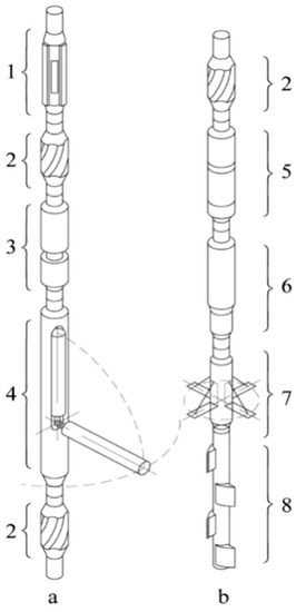
The special BHA used for circular recess drilling (Figure 5a) consists of an anchor (1) of known design, designed to fix the drill string relative to the wellbore, two centralizers (2) used to orient the BHA relative to the axis of the well, a rotary device (3) with remote control, and a special device with a rotating bit (4).
The sequence to obtain circural recesses with this BHA is as follows:drilling of the well of nominal radiusr;the special bottomhole assembly is lowered into the well to a given depth and fixed;washing liquid starts circulation, causes the rock-destroying tool rotation, and serves as a trigger for the remote control system on the circular recess drilling to start;the remote control system provides a control signal to the linear drive which through the rod (1), via the lever mechanism (2), deflects the rock-destroying tool at an angle of 90 degrees (Figure 6);the rotary device (3) rotates the device with the rotary bit around its axis by 360 degrees, and as a result, the circular recess is formed;the rock-destroying tool returns to its original position on the signal of the control system, and the BHA is fixed; andthe BHA rises to a given heighth, after which the whole process is repeated.
After completing the drilling, the tool is removed from the well.
It consists of a hollow bit (see number 10 inFigure 6) with cutters fixed on its surface driven through the gearbox 6 by a section of turbines (8) with movable stators and fixed rotors, or a section of a screw motor with a hollow rotor and torsion bar (not shown) in it. Thus, the assembly scheme of the device for the tool with a diameter of 197 mm makes possible usage of the deflecting bit (10) with a diameter of 140–145 mm with the drive in the form of standard sections of turbine drills or sections of a propeller engine with a hollow rotor with a diameter of 85 mm. Based on the preliminary calculations, the length of the bit is limited to 1.75–2.5 m depending on the bit operation mode, rock mass, and bit cutter charactersitics. We used methods to assess the strength and rigidity of long structures, including pipe columns, pipelines, and special tools operation in the conditions of contact interaction with the elastic environment and at operation in difficult geotechnical conditions [29][30].
The BHA (Figure 5b) is lowered into the well after circular recess drilling destroys the rock mass between the circular recesses. It consists of a section of heavy weighted drill pipes which carries out its orientation relative to the axis of the well; one of the known drill shock absorbers (5) [31][32], which protect the drill string from vibration and control the BHA dynamics [33]; the vibration generator or jar (6); the special device to retract legs (7), which allows independent rotation of the legs around the axis of the BHA; and the section of the eccentric well reamers (6).
The destruction of the rock mass using this bottomhole envisages the following sequence:the BHA is lowered into the well, which is positioned in one of the known ways so that the device to retract the legs is in front of the drilled circular recesses;the legs retract to the circular recess after the command;intensive circulation of the washing liquid begins with simultaneous rotation of the drill string;the axial load is applied to the rock mass, the static component of which is created by the weight of the of heavy weighted drill pipes—due to the operation of the vibrator. As a result, the main cracks appear in the rock and its destruction occurs; andto prevent trapping of the drill string and high-quality cleaning of the well, pieces of rock that fall into the space between the drill string and the walls of the well are further crushed using the section of eccentric expanders 8 (Figure 3) and are carried to the surface with flushing fluid.
After the destruction of one cantilever rock mass, further destruction of the following is carried out, after which the BHA is removed from the well.
Increasing the contact area between the bottomhole and the reservoir area (increasing the filtration surface area, opening new channels for filtering fluids into the well, etc.) allows hydrocarbon fluid production to be intensified. It should be emphasized that this is not a classic reaming of the wellbore with traditional reamers, but well diameter increasing more than five times in a clearly defined interval. The greater effect of well diameter change on the flow rate is associated with the more significant well deviation from the hydrodynamic perfection of its completion and the more expressed nonlinearity of the fluid filtration law [8][9]. In this case, the predicted increase in the well flow rate can reach the value ofn2/3wheren—the multiplicity of the well diameter—increases.
We propose the innovative technology for local well diameter increasing (more than five times) in a clearly defined interval. At the first stage, large-diameter circular recesses are drilled in planes that are perpendicular to the well axis. The second stage is the destruction, grinding, and removal to the surface of the rocks located between the drilled circular recesses. Static and dynamic axial forces applied to the special bottomhole assembly are used for rock mass destruction.
The sequence of technological operations on the local increase in the diameter of the wellbore is presented. The designs of drill string configurations that should be used to implement the proposed technology are proposed:layout for drilling disk and conical recesses;layout for destruction and crushing of rock mass.a special tool with a rotating bit for drilling disk recesses has been developed, its design is presented and the principle of operation is described. The designs of bottomhole assembly for the proposed technology implementation have been presented:BHA for circular and conical recess drilling; andBHA for rock mass destruction.
A special tool for circular recess drilling and its design are presented, and the principle of its operation is described.
In order to substantiate the possibility of the technology implementation and for determination of its applicability limits, we formulated and obtained a solution to the problem of the limit equilibrium of the rock mass formed between two adjacent circular recesses. We obtained analytical relations to specify the admissible radius of the circular recesses (formula 3) and admissible thickness of the rock mass (formula 4) on the condition of the safe performance of planned technological processes. In general, the possibility of the proposed technology application for typical reservoir rocks is substantiated, in particular for siltstone, sandstone, fine-grained limestone, and dolomite. The tasks of the next stages of our research are field and bench tests of the special tool with the rotating bit and evaluation of the quality of sludge removal when drilling circular recesses of large diameter.
Today, the oil and gas industry are actively developing and improving the classical [34][35][36] and developing and testing new technologies to increase the productivity of wells [2][37][38]. Each of these technologies has its advantages and disadvantages, as well as economically feasible applications [1][36]. To destroy the rock mass, our technology effectively uses the axial force provided by the weight of existing drilling tools so the technology is energy efficient. This favourably differs the proposed technology from others aimed at increasing the contact area between the bottomhole and the collector area.


