In recent years, interest in in-pipe robot research has been steadily increasing. This phenomenon reflects the necessity and urgency of pipe inspection and rehabilitation as several pipe networks have become outdated around the globe. In-pipe robots can be divided into several groups in accordance with their locomotion principles, each with its own advantages and best suited application scope. Research on the screw drive in-pipe robot (SDIR) has had a rising trend due to the robot’s simple driving mechanism design and numerous advantages.
- screw drive
- in-pipe robot
- driving mechanisms
- motion
- pipe inspection and rehabilitation
Please note: Below is an entry draft based on your previous paper, which is wrirren tightly around the entry title. Since it may not be very comprehensive, we kindly invite you to modify it (both title and content can be replaced) according to your extensive expertise. We believe this entry would be beneficial to generate more views for your work. In addition, no worry about the entry format, we will correct it and add references after the entry is online (you can also send a word file to us, and we will help you with submitting).
Definition
In recent years, interest in in-pipe robot research has been steadily increasing. This phenomenon reflects the necessity and urgency of pipe inspection and rehabilitation as several pipe networks have become outdated around the globe. In-pipe robots can be divided into several groups in accordance with their locomotion principles, each with its own advantages and best suited application scope. Research on the screw drive in-pipe robot (SDIR) has had a rising trend due to the robot’s simple driving mechanism design and numerous advantages.
1. Introduction
Transporting hazardous fluids via pipeline is safer than through other ways of transportation. Therefore, pipelines are widely used for transporting fluids in various fields [1]. The fluid transported inside the pipeline will cause damage to its inner wall due to high temperature, high pressure, high flow rate, and corrosion [2][3][2,3]. Hazardous fluids may leak if the pipeline is damaged, which may cause a large number of casualties, serious property damage, and environmental pollution [4]. Global pipelines have a large number of safety hazards which can be managed by conducting the regular inspection and maintenance of pipelines [5]. In-pipe robots are electromechanical systems carrying instruments and working tools that can perform inspections and repairs in the pipeline [6][7][6,7]. At present, in-pipe robots are mainly divided into active and passive types.
Passive in-pipe robots move passively in pipelines by fluid energy and have been widely used to detect large-diameter and long-distance pipelines [8]. However, small-diameter pipes (200 mm or less) often contain numerous special parts, such as elbows, branches, reducers, and valves. Passive in-pipe robots are uncontrollable and cannot adapt to sharp changes in pipe direction and diameter. Therefore, numerous studies have proposed active in-pipe robots which can travel autonomously in pipelines. At present, these robots are mainly divided into six types: Gravity walking wheel (track) type [9][10][11][9,10,11]; wall-press wheel (track) type [12][13][14][15][16][12,13,14,15,16]; screw type [17][18][19][20][21][17,18,19,20,21]; inchworm (caterpillar) type [22][23][22,23]; walking type [24][25][24,25]; and snake type [26][27][28][26,27,28].
Among the active in-pipe robots, the screw drive in-pipe robot (SDIR) has been increasingly researched due to its simple driving (single power source) and numerous advantages [29]. Figure 1 shows several prototypes of the SDIRs proposed and fabricated by the authors.
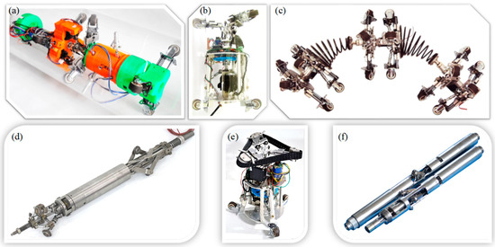
Figure 1.
a
b
c
d
e
f
In comparison with other types of in-pipe robots, the SDIR has the following advantages.
-
Climbs vertical pipelines with ease
-
Is easily sealed off
-
Does not damage the inner wall, as it does not drag its body
-
Has flexible movement
-
Does not block the fluid flow inside the pipe
-
Can adapt to changes in inner pipe diameter
-
Has wider contact area than other robot types, which may dissipate contact force to generate propulsive force
-
Is generally difficult to back-drive (e.g., screw locomotion robots) due to its angled wheels or tracks and is thus effective in high-flow networks
As shown in Figure 2, the driving wheel rotates around the pipe axis under the action of torque. An SDIR requires only one motor to drive, which greatly simplifies the structure and control system. SDIRs are wall-pressed, which allows them to easily climb vertical pipes [30].
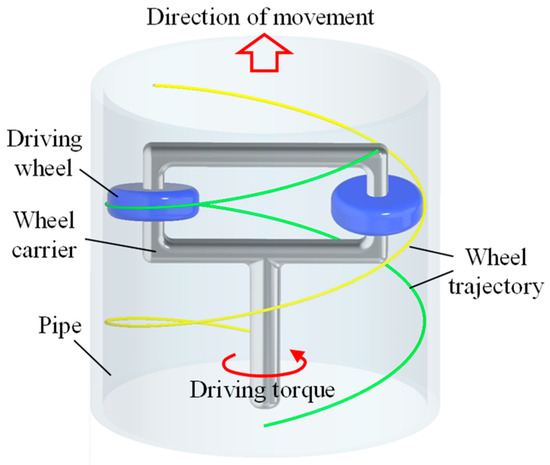
Figure 2.
In recent years, more and more researchers have begun to study different types of SDIRs. Horodinca et al. presented an intermediate articulated passive screw drive in-pipe robot (PSDIR) [31]. Kakogawa et al. designed an active turning SDIR with a controllable shaft inclination [32]. Lee et al. presented a crab-shaped active screw drive in-pipe robot (ASDIR) [33]. Ma et al. studied a differential-driven screw in-pipe robot [34][35][34,35] and an ASDIR that can travel in circular and square pipes [36]. Ren et al. proposed an ASDIR based on compound planetary gearing [37][38][37,38], a variable-pitch SDIR [39], an inchworm SDIR [40], and a helical-contact deformation measuring method in pipelines [41]. The abovementioned SDIRs have different structures and driving principles, and each has its own advantages and application scope.
2. Mechanisms and Driving Principle
The structure of an SDIR is divided into passive and active types. The structural characteristics of the two types of SDIRs are described in the following parts.
2.1. PSDIR
Figure 3 shows the basic structure of the PSDIR. The driving wheel is mounted on the wheel carrier with an angle (helical angle) between the wheel and pipe axes. The driving wheel is pressed firmly against the inner wall of the pipe to generate adequate friction force. The driving motor shaft rotates to drive the rotor carrier. The driving wheel is driven by the wheel carrier and rotates around its own axis under the action of friction while revolving around the central axis of the pipeline. The rotation of the driving wheels drives the robot to move along the pipe axis. The main body is the stator, which is equipped with a driving motor and control circuit. Guiding wheels with a wheel plane parallel to the pipe axis are mounted on the main body and pressed firmly against the inner wall of the pipe to generate friction force for balancing the reverse torque generated by the rotor rotation. When the driving wheel carrier rotates around the pipe axis, the driving wheel will make a screw motion on the inner wall of the pipe. In this case, the driving wheel is passively rotated; this type of robot is called a "“PSDIR."”
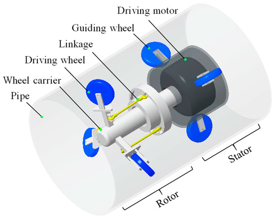
Figure 3.
The helical angle between the driving wheel and pipe axes directly reflects the motion and mechanical properties of the SDIR. The helical angle can be adjusted through gears or linkages (Figure 3). The rotation angle of the extension arm of the driving wheel carrier is adjusted by the linkage to change the inclination angle of the driving wheel. When the helical angle is increased, the traveling speed of the robot in the pipeline and the pitch of the helical trajectory of the driving wheels are increased. Figure 1b shows a prototype of the PSDIR. In order to improve the motion stability and obstacle negotiating ability of the SDIR, crawler wheels were added in the prototype shown in Figure 1e compared to the prototype in Figure 1b.
The rotation of the PSDIR rotor drives the driving wheels to rotate. The rotation of the ASDIR driving wheels drive the rotor to rotate.
2.2. ASDIR
The driving wheel of the ASDIR is driven by a motor through gear transmission; this is the largest difference between the ASDIR and PSDIR [17][42][17,42]. As shown in Figure 4, the power output from the motor is split by the planetary transmission mechanism to drive the driving wheel directly; this type of robot is called an "“ASDIR"”.
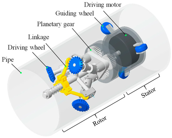
Figure 4.
The driving force of the ASDIR acts directly on the driving wheel. When the driving motor outputs the driving force, it will generate a reverse torque. On the basis of the difference in the anti-torque balance structure, the ASDIR based on the compound planetary gearing has the following two structures.
The first structure is a support-balanced transmission (Figure 5a). The robot structure is divided into two parts, namely, rotor and stator. The planet carrier and gear train act as rotors. The driving motor is fixed in the main body as a stator. The friction between the guiding wheels and pipe wall is balanced with the counter-torque of the motor. The driving wheels are driven actively through the two-stage planetary gear train. The pipe acts as an outer ring gear of the planetary gear train and meshes with the driving wheel (second-stage planetary gear). Figure 1d shows a prototype of the support-balanced type ASDIR.
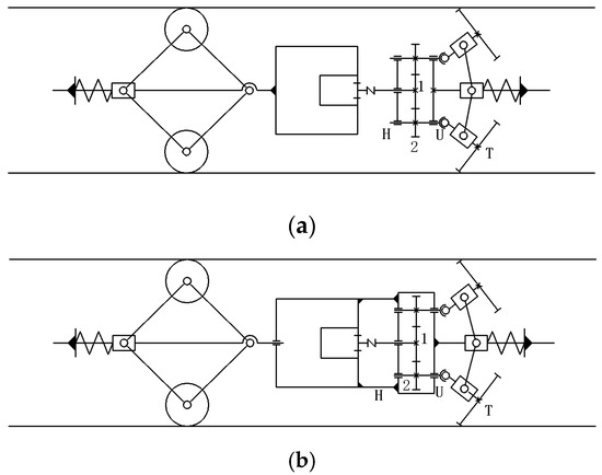
Figure 5.
a
b
The second structure is a self-balancing transmission (Figure 5b). The stator only plays a centering role, and the counter-torque is not required for balancing. The driving motor is fixed in the main body. The main body acts as rotor and is fixed to the planet carrier. The reverse torque of the motor body is absorbed by the rotor. The motor housing is rotatably coupled to the stator to transmit only axial tension without transmitting torque. The counter-torque of the motor can be balanced by the structure itself. The robot can be connected without the stator support structure, and only the same rotor drive modules can be connected in series to obtain a great axial traction force. Figure 1f shows a prototype of the self-balancing type ASDIR.
3. Motion Behavior
Conventional in-pipe robots are mostly applicable to inspection in a horizontal straight pipe or a straight pipe with small slope. Since urban gas pipelines have complicated structures due to complex distribution networks, researchers are increasingly likely to investigate in-pipe robots that are applicable to complex pipelines in recent years. Complex pipe structures include horizontal, vertical, curved, and branch. The robot must have a steering function to pass through the complex pipeline smoothly. At present, four types of steering mechanism are known, i.e., articulated, differential, variable helical pitch, and spring-connected types.
Articulated steering mechanism is inspired by the movement of a snake or annelid. The guiding and driving parts of the single SDIR are often connected by joints (Figure 6), and the multi-robot modules are connected by joints (Figure 7) [43]. The robot body rotates relative to each other in a confined space.
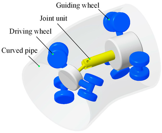
Figure 6. Articulated steering mechanism (single robot).
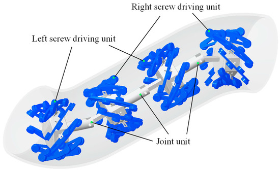
Figure 7. Articulated steering mechanism (multi-robot modules).
Articulated steering mechanisms are divided into two types, i.e., controllable and uncontrollable. An uncontrollable steering mechanism often relies on the bending and deformation of the pipe to force the robot'’s joint to rotate, enabling the robot to steer and adapt to the changes of the pipe [44]. However, the passive steering mechanism cannot select the path when encountering the branch pipes. Therefore, the uncontrollable steering mechanism is often only applicable to curved pipes. A controllable steering mechanism relies on the operators to control the robot actuators, such as a servo motor and an air pump, to realize active steering [45][46][47][48][49][45,46,47,48,49]. The controllable steering mechanism has an active path selectivity and a wide range of applications.
The screw angle of the driving wheel can be adjusted by the adaptive mechanism through the differential principle and pipe binding force. In pipes with different radii of curvature, the robot can always adaptively find the corresponding screw angle [50]. As shown in Figure 8, the motor acts as an input and three bevel gears attached to the screw wheels act as outputs. The motor transmits power to the planet carrier H1 of the planetary gear train 1 through a worm gear mechanism. The output ring gear gr3 of the planetary gear train 1 is connected to the input carrier H2 of the planetary gear train 2. The two sets of planetary gear trains form a three-axis differential mechanism. The planet carrier H1 is the input to the three-axle differential gear train, and the sun gears gs1 and gs6 and ring gear gr5 are the three outputs. To convert these outputs into helix angles, a circular symmetrical output gear transmission was designed. For example, the rotational motion of the sun gear gs6 is transmitted to the spur gear gs7 through its coaxial spur gear gs6′, and the transmission direction is changed by two bevel gears gb7′ and gb8. As the robot moves in the curved pipe, the force Fw1 on the outward screw roller will be greater than the force Fw2 on the inner screw roller. The differential mechanism adaptively adjusts the screw angle without any active control until the speed and force reach a new balance.
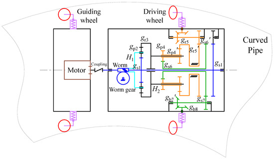
Figure 8. Schematic diagram of the adaptive mechanism of differential gear transmission [50].
Figure 9 shows the variable helical pitch mechanism steering in curved pipes by adjusting the helical angle of each driving wheel [39]. One driving motor drives the wheel carrier. The lifting and tilting degrees of the circular outer ring are controlled by the expansion and contraction of three linear stepping motor shafts, thereby controlling the link movement. The movement of the linkage can adjust the inclination angle of the axis on the wheel carrier, thereby changing the helical angle of the three driving wheels. This type of robot has two modes of motion. When the amounts of expansion and contraction of the three linear stepping motor shafts are equal, the corresponding three driving wheels have the same amount of change in the helical angle; thus, the robot is in a variable speed motion. When the amounts of expansion and contraction of the three linear stepping motor shafts are not equal, the amount of change in the helical angle of the corresponding three driving wheels is not equal; thus, the robot is in a steering motion. When the robot is passing through a curved pipe, the helical angles of the inner driving wheels are reduced, whereas those of the outer driving wheels are increased. v2 becomes greater than v1 by controlling different helical angles to prevent the robot from being eccentrically stuck in the pipeline. Figure 1a shows a prototype of the variable helical pitch SDIR.
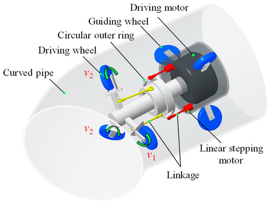
Figure 9. Variable helical pitch steering mechanism.
The spring-connected steering mechanism is inspired by the inchworm motion [2]. As shown in Figure 10, conical springs are used to connect several SDIR modules. Each robot module is independently driven. When the spring-connected SDIR is carrying a small load, all the springs are in free lengths. Therefore, all the modules move at the same speed; thus, the energy consumption is the minimum. To increase the load capacity, the spring is compressed by controlling the moving speed of each module so that strain energy can be stored in the robot. When cornering, the speed of each module can be controlled to achieve the inchworm movement. When entering the curved pipe, the rear module pushes the front module to assist it in entering the curved pipe. When leaving the curved pipe, the front module can pull the rear module, which remains in the curved pipe, to assist leaving. The spring-connected SDIR modules cooperate with each other through the curved pipe. Figure 1c shows a prototype of the inchworm type SDIR.
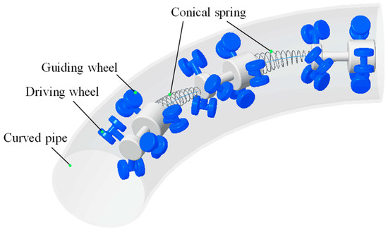
Figure 10. Spring-connected modular steering mechanism.
4. Summary
The specifications for all the platforms of SDIRs reviewed in this paper are summarized in Table 1. Please note that the present work was never intended to be complete or exhaustive, but it was intended to qualitatively provide a comprehensive status for SDIR technology from the point of view of robotic platforms.
Table 1. Comparisons between different types of SDIRs.
5. Conclusions
Pipeline robots have various types, each with its own advantages and different application scopes. An SDIR is simple to drive (single power source), can climb vertical pipelines with ease, and has a wider contact area than other robot types, which may dissipate contact force to generate propulsive force. An SDIR is suitable for small-diameter (less than 200 mm) pipe inspection; thus, it has attracted several scholars' attention. This study introduces the historical research on the SDIR, especially summarizing and emphasizing the structure, driving principle, and motion and mechanical behaviors of its different types. This study can provide an up-to-date reference for researchers to conduct further analysis on SDIRs. Researchers hope that SDIRs can smoothly travel in inclined pipes, elbows, branches, and reducers. SDIRs with large traction force and steering capabilities are becoming more and more popular. The modules of the modular SDIR can work cooperatively with each other and have broad prospects for development in the future. In the next few years, the development of in-pipe robotics will continue to grow as the number of global pipe networks grows. The structure and function of the SDIR will be gradually improved. Adapting to complex pipe networks and structures with large traction force will become the development trend of SDIRs.
Ref NO. |
Author Name |
In-Pipe Geometry |
Length (mm) |
Weight (kg) |
Diameter Range (mm) | Traction Force (N) |
Application |
|||||||
|
Slope (°) |
Elbow (°) |
Branch |
|||||||
|
[2] |
Liu Qingyou |
0 |
90 and 120 |
None |
Unk. |
Unk. |
200 |
Unk. |
Gas and liquid |
|
[17,37] |
Tao Ren |
Unk. |
90 |
None |
730 |
Unk. |
90–120 |
500 |
Oil and gas |
|
[19] |
Pen Li |
0 |
Unk. |
None |
349 |
3.35 |
173–200 |
Unk. |
Other |
|
[20,32,45] |
Atsushi Kakogawa |
0 |
90 |
T |
175.8 |
0.7 |
109–129 |
Unk. |
Other |
|
[31] |
Mihaita Horodinca |
0 |
Unk. |
None |
Unk. |
1.3 |
170 |
5 |
Other |
|
0.47 |
70 |
3 |
|||||||
|
0.48 |
70 |
3 |
|||||||
|
0.25 |
40 |
1 |
|||||||
|
[33] |
Dongwoo Lee |
0 and 90 |
90 |
T |
280 |
3.6 |
259–305 |
Unk. |
Other |
|
[34,50] |
Te Li |
0 and 90 |
45 and 90 |
None |
Unk. |
2.05 |
Unk. |
Unk. |
Other |
|
[38] |
Yujia Li |
Unk. |
Unk. |
None |
900 |
Unk. |
105 |
1620 |
Oil and gas |
|
[39] |
Tao Ren |
Unk. |
135 |
Unk. |
230 |
Unk. |
160–210 |
Unk. |
Oil and gas |
|
[47] |
A. Brunete |
0, 30, 60 and 90 |
90 |
None |
About 215 |
About 0.1 |
40 |
Unk. |
Other |
|
[48] |
Toshio Fukuda |
0 |
90 |
T |
90–130 |
0.08 |
32–65 |
24 |
Other |
|
[49] |
Sari Yabe |
90 |
90 |
T |
215 |
1.85 |
180–220 |
Unk. |
Wastewater |
|
Ref NO. |
Author Name |
In-Pipe Geometry |
Length (mm) |
Weight (kg) |
Diameter Range (mm) |
Traction Force (N) |
Application |
||
|
Slope (°) |
Elbow (°) |
Branch |
|||||||
|
[2] |
Liu Qingyou |
0 |
90 and 120 |
None |
Unk. |
Unk. |
200 |
Unk. |
Gas and liquid |
|
Tao Ren |
Unk. |
90 |
None |
730 |
Unk. |
90–120 |
500 |
Oil and gas |
|
|
[19] |
Pen Li |
0 |
Unk. |
None |
349 |
3.35 |
173–200 |
Unk. |
Other |
|
Atsushi Kakogawa |
0 |
90 |
T |
175.8 |
0.7 |
109–129 |
Unk. |
Other |
|
|
[31] |
Mihaita Horodinca |
0 |
Unk. |
None |
Unk. |
1.3 |
170 |
5 |
Other |
|
0.47 |
70 |
3 |
|||||||
|
0.48 |
70 |
3 |
|||||||
|
0.25 |
40 |
1 |
|||||||
|
[33] |
Dongwoo Lee |
0 and 90 |
90 |
T |
280 |
3.6 |
259–305 |
Unk. |
Other |
|
Te Li |
0 and 90 |
45 and 90 |
None |
Unk. |
2.05 |
Unk. |
Unk. |
Other |
|
|
[38] |
Yujia Li |
Unk. |
Unk. |
None |
900 |
Unk. |
105 |
1620 |
Oil and gas |
|
[39] |
Tao Ren |
Unk. |
135 |
Unk. |
230 |
Unk. |
160–210 |
Unk. |
Oil and gas |
|
[47] |
A. Brunete |
0, 30, 60 and 90 |
90 |
None |
About 215 |
About 0.1 |
40 |
Unk. |
Other |
|
[48] |
Toshio Fukuda |
0 |
90 |
T |
90–130 |
0.08 |
32–65 |
24 |
Other |
|
[49] |
Sari Yabe |
90 |
90 |
T |
215 |
1.85 |
180–220 |
Unk. |
Wastewater |
5. Conclusions
Pipeline robots have various types, each with its own advantages and different application scopes. An SDIR is simple to drive (single power source), can climb vertical pipelines with ease, and has a wider contact area than other robot types, which may dissipate contact force to generate propulsive force. An SDIR is suitable for small-diameter (less than 200 mm) pipe inspection; thus, it has attracted several scholars’ attention. This study introduces the historical research on the SDIR, especially summarizing and emphasizing the structure, driving principle, and motion and mechanical behaviors of its different types. This study can provide an up-to-date reference for researchers to conduct further analysis on SDIRs. Researchers hope that SDIRs can smoothly travel in inclined pipes, elbows, branches, and reducers. SDIRs with large traction force and steering capabilities are becoming more and more popular. The modules of the modular SDIR can work cooperatively with each other and have broad prospects for development in the future. In the next few years, the development of in-pipe robotics will continue to grow as the number of global pipe networks grows. The structure and function of the SDIR will be gradually improved. Adapting to complex pipe networks and structures with large traction force will become the development trend of SDIRs.
References
1. Ramírez-Camacho, J.G.; Carbone, F.; Pastor, E.; Bubbico, R.; Casal, J. Assessing the consequences of pipeline
accidents to support land-use planning. Saf. Sci. 2017, 97, 34–42. [CrossRef]
2. Liu, Q.; Ren, T.; Chen, Y. Characteristic analysis of a novel in-pipe driving robot. Mechatronics 2013, 23,
419–428. [CrossRef]
3. Bubbico, R.; Carbone, F.; Ramírez-Camacho, J.G.; Pastor, E.; Casal, J. Conditional probabilities of post-release
events for hazardous materials pipelines. Process Saf. Environ. Protect. 2016, 104, 95–110. [CrossRef]
4. Siler-Evans, K.; Hanson, A.; Sunday, C.; Leonard, N.; Tumminello, M. Analysis of pipeline accidents in the
United States from 1968 to 2009. Int. J. Crit. Infrastruct. Protect. 2014, 7, 257–269. [CrossRef]
5. Schempf, H.; Mutschler, E.; Gavaert, A.; Skoptsov, G.; Crowley, W. Visual and nondestructive evaluation
inspection of live gas mains using the Explorer™ family of pipe robots. J. Field Robot. 2010, 27, 217–249.
[CrossRef]
6. Mills, G.; Jackson, A.; Richardson, R. Advances in the Inspection of Unpiggable Pipelines. Robotics 2017, 6,
36. [CrossRef]
7. An, J.; Lee, G.; Oh, I.; Moon, H.; Ryew, S. Navigation-oriented design for in-pipe robot in recursively divided
sampling space with rapidly exploring random tree. J. Mech. Sci. Technol. 2017, 31, 5987–5995. [CrossRef]
8. Datta, S.; Sarkar, S. A review on different pipeline fault detection methods. J. Loss Prev. Process Ind. 2016, 41,
97–106. [CrossRef]
9. Song, Z.; Ren, H.; Zhang, J.; Ge, S.S. Kinematic analysis and motion control of wheeled mobile robots in
cylindrical workspaces. IEEE Trans. Autom. Sci. Eng. 2016, 13, 1207–1214. [CrossRef]
10. Hansen, P.; Alismail, H.; Rander, P.; Browning, B. Visual mapping for natural gas pipe inspection. Int. J.
Robot. Res. 2015, 34, 532–558. [CrossRef]
11. Hayat, A.; Elangovan, K.; Rajesh Elara, M.; Teja, M. Tarantula: Design, modeling, and kinematic identification
of a quadruped wheeled robot. Appl. Sci. 2019, 9, 94. [CrossRef]
12. Kim, H.M.; Choi, Y.S.; Lee, Y.G.; Choi, H.R. Novel mechanism for in-pipe robot based on a multiaxial
differential gear mechanism. IEEE/ASME Trans. Mech. 2017, 22, 227–235. [CrossRef]
13. Kakogawa, A.; Ma, S.; Hirose, S. An in-pipe robot with underactuated parallelogram crawler modules. In
Proceedings of the 2014 IEEE International Conference on Robotics and Automation (ICRA), Hong Kong,
China, 31 May–7 June 2014; pp. 1687–1692.
14. Kwon, Y.S.; Yi, B.J. Development of a pipeline inspection robot system with diameter of 40 mm to 70 mm
(Tbot-40). In Proceedings of the 2010 IEEE International Conference on Mechatronics and Automation, Xi’an,
China, 4–7 August 2010; pp. 258–263.
15. Mateos, L.A. LaMMos-Latching Mechanism based on Motorized-screw for Reconfigurable Robots and
Exoskeleton Suits. arXiv 2017, arXiv:1801.00035.
16. Kwon, Y.S.; Yi, B.J. Design and motion planning of a two-module collaborative indoor pipeline inspection
robot. IEEE Trans. Robot. 2012, 28, 681–696. [CrossRef]
17. Ren, T.; Liu, Q.; Li, Y.; Chen, Y. Design, analysis and innovation in variable radius active screw in-pipe drive
mechanisms. Int. J. Adv. Robot. Syst. 2017, 14, 1–9. [CrossRef]
18. Chen, Y.; Liu, Q.; Ren, T. A simple and novel helical drive in-pipe robot. Robotica 2015, 33, 920–932. [CrossRef]
19. Li, P.; Ma, S.; Li, B.; Wang, Y.; Liu, Y. Self-rescue mechanism for screw drive in-pipe robots. In Intelligent
Robots and Systems (IROS). In Proceedings of the 2010 IEEE/RSJ International Conference on Intelligent
Robots and Systems, Taipei, Taiwan, 18–22 October 2010; pp. 2843–2849.
20. Kakogawa, A.; Nishimura, T.; Ma, S. Designing arm length of a screw drive in-pipe robot for climbing
vertically positioned bent pipes. Robotica 2016, 34, 306–327. [CrossRef]
21. Tourajizadeh, H.; Rezaei, M.; Sedigh, A.H. Optimal Control of Screw In-pipe Inspection Robot with
Controllable Pitch Rate. J. Intell. Robot. Syst. 2018, 90, 269–286. [CrossRef]
22. Kamata, M.; Yamazaki, S.; Tanise, Y.; Yamada, Y.; Nakamura, T. Morphological change in peristaltic crawling
motion of a narrow pipe inspection robot inspired by earthworm’s locomotion. Adv. Robot. 2018, 32, 386–397.
[CrossRef]
23. Nakazato, Y.; Sonobe, Y.; Toyama, S. Development of an in-pipe micro mobile robot using peristalsis motion.
J. Mech. Sci. Technol. 2010, 24, 51–54. [CrossRef]
24. Zagler, A.; Pfeiffer, F. “MORITZ” a pipe crawler for tube junctions. In Proceedings of the 2003
IEEE International Conference on Robotics and Automation (Cat. No.03CH37422), Taipei, Taiwan,
14–19 September 2003; Volume 3, pp. 2954–2959.
25. Machado, J.T.; Silva, M.F. An overview of legged robots. In International Symposium on Mathematical Methods
in Engineering; MME Press: Ankara, Turkey, 2017.
26. Trebuna, F.; Virgala, L.; Pastor, M.; Liptak, T.; Mikova, L. An inspection of pipe by snake robot. Int. J. Adv.
Robot. Syst. 2016, 13. [CrossRef]
27. Granosik, G. Hypermobile robots–the survey. J. Intell. Robot. Syst. 2014, 75, 147–169. [CrossRef]
28. Zhang, X.; Liu, J.; Ju, Z.; Yang, C. Head-raising of snake robots based on a predefined spiral curve method.
Appl. Sci. 2018, 8, 2011. [CrossRef]
29. Ismail, I.N.; Anuar, A.; Sahari, K.S.M.; Baharuddin, M.Z.; Fairuz, M.; Jalal, A.; Saad, J.M. Development of
in-pipe inspection robot: A review. In Proceedings of the 2012 IEEE Conference on Sustainable Utilization
and Development in Engineering and Technology (STUDENT), Kuala Lumpur, Malaysia, 6–9 October 2012;
pp. 310–315.
30. Ren, T.; Liu, Q.; Li, Y.; Chen, Y. Basic characteristics of a novel in-pipe helical drive robot. Int. J.
Mechatron. Autom. 2014, 4, 127–136.
31. Horodinca, M.; Doroftei, I.; Mignon, E.; Preumont, A. A simple architecture for in-pipe inspection robots.
In Proceedings of the International Colloquium on Autonomous and Mobile Systems, Magdeburg, Germany,
25–26 June 2002; pp. 61–64.
32. Kakogawa, A.; Nishimura, T.; Ma, S. Development of a screw drive in-pipe robot for passing through bent
and branch pipes. In Proceedings of the 2013 44th International Symposium on Robotics (ISR), Seoul, Korea,
24–26 October 2013; pp. 1–6.
33. Lee, D.; Park, J.; Hyun, D.; Yook, G.; Yang, H.S. Novel mechanisms and simple locomotion strategies for an
in-pipe robot that can inspect various pipe types. Mech. Mach. Theory 2012, 56, 52–68. [CrossRef]
34. Li, T.; Ma, S.; Li, B.; Wang, M.; Li, Z.; Wang, Y. Development of an in-pipe robot with differential screw angles
for curved pipes and vertical straight pipes. J. Mech. Robot. 2017, 9, 051014. [CrossRef]
35. Li, P.; Ma, S.; Lyu, C.; Jiang, X.; Liu, Y. Energy-efficient control of a screw-drive pipe robot with consideration
of actuator’s characteristics. Robot. Biomim. 2016, 3, 11. [CrossRef]
36. Li, P.; Tang, M.; Lyu, C.; Fang, M.; Duan, X.; Liu, Y. Design and analysis of a novel active screw-drive pipe
robot. Adv. Mech. Eng. 2018, 10. [CrossRef]
37. Ren, T.; Chen, Y.; Liu, Q. A helical drive in-pipe robot based on compound planetary gearing. Adv. Robot.
2014, 28, 1165–1175.
38. Li, Y.; Liu, Q.; Chen, Y.; Ren, T. Design and analysis of an active helical drive downhole tractor. Chin. J. Mech.
Eng. 2017, 2, 428–437. [CrossRef]
39. Ren, T.; Liu, Q.; Chen, Y.; Ji, S. Variable pitch helical drive in-pipe robot. Int. J. Robot. Autom. 2016, 31,
263–271. [CrossRef]
40. Liu, Q.; Chen, Y.; Ren, T.; Wei, Y. Optimized inchworm motion planning for a novel in-pipe robot. Proc. Inst.
Mech. Eng. Part C J. Mech. Eng. Sci. 2014, 228, 1248–1258. [CrossRef]
41. Li, Y.; Liu, Q.; Chen, Y.; Li, M. Helical-contact deformation measuring method in oil–gas pipelines. Int. J.
Robot. Autom. 2017, 32. [CrossRef]
42. Liu, Q.; Ren, T.; Chen, Y. Actively Driven Spiral Pipeline Robot. U.S. Patent 9,316,340, 19 April 2016.
43. Xiao, X.; Murphy, R. A review on snake robot testbeds in granular and restricted maneuverability spaces.
Robot. Auton. Syst. 2018, 110, 160–172. [CrossRef]
44. HORODINCĂ, M.; PREUMONT, A.; BURDA, I. The heli-pipe inspection robots architecture for curved
pipes. In Proceedings of the International Conference of Manufacturing Systems ICMS 2003, Ogun State,
Nigeria, 16–22 November 2003; pp. 149–154.
45. Nishimura, T.; Kakogawa, A.; Ma, S. Improvement of a screw drive in-pipe robot with pathway selection
mechanism to pass through T-branches. J. Robot. Mechatron. 2013, 25, 340–346. [CrossRef]
46. Fukushima, H.; Satomura, S.; Kawai, T.; Tanaka, M.; Kamegawa, T.; Matsuno, F. Modeling and control of a
snake-like robot using the screw-drive mechanism. IEEE Trans. Robot. 2012, 28, 541–554. [CrossRef]
47. Runete, A.; Hernando, M.; Gambao, E.; Torres, J.E. A behaviour-based control architecture for heterogeneous
modular, multi-configurable, chained micro-robots. Robot. Auton. Syst. 2012, 60, 1607–1624. [CrossRef]
48. Fukuda, T.; Hosokai, H.; Uemura, M. Rubber gas actuator driven by hydrogen storage alloy for in-pipe
inspection mobile robot with flexible structure. In Proceedings of the 1989 International Conference on
Robotics and Automation, Scottsdale, AZ, USA, 14–19 May 1989; pp. 1847–1852.
49. Yabe, S.; Masuta, H.; Lim, H.O. New in-pipe robot capable of coping with various diameters. In Proceedings
of the 2012 12th International Conference on Control, Automation and Systems, JeJu Island, Korea,
17–21 October 2012; pp. 151–156.
50. Li, T.; Ma, S.; Li, B.; Wang, M.; Wang, Y. Axiomatic design method to design a screw drive in-pipe robot
passing through varied curved pipes. Sci. China Technol. Sci. 2016, 59, 191–202. [CrossRef]
51. Aligia, D.A.; Magallan, G.A.; De Angelo, C.H. EV Traction Control Based on Nonlinear Observers Considering
Longitudinal and Lateral Tire Forces. IEEE Trans. Intell. Transp. Syst. 2018, 19, 2558–2571. [CrossRef]
52. Ward, C.C.; Iagnemma, K. A dynamic-model-based wheel slip detector for mobile robots on outdoor terrain.
IEEE Trans. Robot. 2008, 24, 821–831. [CrossRef]

