1000/1000
Hot
Most Recent
 +1 point
AlCr-based hard nitride coatings with different chemical compositions and architectures have been successfully developed and applied over the last few decades. Coating properties are mainly influenced by deposition conditions and the Al/Cr content. The fcc structure is dominant for an Al-content up to Al0.7Cr0.3N and is preferred for most cutting applications. Different (AlCrX)N alloying concepts, including X = Si, W, B, V, have been investigated in order to enhance oxidation resistance and wear behaviour and to provide tribological properties. AlCr-based oxynitrides and even pure oxides (Al1−xCrx)2O3 with different crystalline structures have been explored. Multi- and nanolayered coatings within the AlCr materials system, as well as in combination with (TiSi)N, for example, have also been implemented industrially. The dominant deposition technology is the vacuum arc process. Recently, advanced high-power impulse magnetron sputtering (HiPIMS) processes have also been successfully applied on an industrial scale.
Surface solutions using PVD (Physical Vapor Deposition) coatings for the improvement of the wear resistance and tribological properties of tools and components started on an industrial scale around the middle of the 1970s in the Soviet Union. The first component coating was MoN [1]. The first successful industrial coating for tooling applications in Western Europe was the “golden” TiN coating applied by low-voltage arc evaporation developed at Oerlikon Balzers [2]. A modification of this coating with carbon followed, and the TiNC coating types were implemented in mass production at the end of the 1980s. In parallel, Cr-based coatings were also introduced, including modifications using oxygen and carbon [3]. Besides nitride, carbonitride and oxynitride coatings, hard amorphous carbon coatings, the DLC (Diamond Like Carbon) coatings, were developed and applied as well [4][5]. These coatings were deposited using several coating architectures [6]. Many coating developments focused on alloying TiN using different additional elements [5].
The most important industrial development after TiN, CrN and DLC was achieved in the Ti-Al-N system [7]. Around the year 2000, this coating family was the dominant coating, especially for cutting tools [8][9]. However, in the Ti-Al-N system, only minor improvements of coating properties and the performance of cutting tool applications were possible, e.g., by alloying with Si, Y, Cr, C, O [10][11][12][13]. A big step forward was achieved through the investigation of totally new coating compositions. This led to the development of a new coating generation based on Al-Cr-N. Coatings in the AlCrN system span the compositional range from Al-rich to Cr-rich. In this paper, the terminology CrAl-based is used for coatings with a Cr content that is higher than that of Al (Cr/Al > 1 in at.%), and conversely, AlCr-based is used for coatings in which Al/Cr > 1.
Results dealing with coatings with a low Al content (Al/(Al + Cr) ratio < 0.5) and (CrAl)N coatings, deposited by sputtering, were published for the first time in 1990 [14][15]. In the same year, coatings with an Al/(Al + Cr) composition of about 0.5 deposited using a modified hollow cathode discharge process were also presented [16]. Arc evaporation was used to deposit (AlCr)N coatings with a high Al content with an (Al/(Al + Cr) ratio of >0.5 [17][18]. The first multilayer coating with an Al content greater than the Cr content was a multilayer architecture with CrN [19]. Another big step was the development of (TiSi)N coatings [20]. Coating solutions were also developed which combined the two coating types in multilayer structures [21].
A challenge for turning tools was, and still is in part, the development of alpha-alumina using PVD. A PVD solution to add metallic doping elements to aluminium was patented in 1992 [22]. Processes to deposit oxides based on arc evaporation were successfully developed on the basis of Al-Cr cathodes [23].
Various deposition technologies have been used to synthesise (CrAl)N and (AlCr)N coatings over a period of about 30 years. Basic information about the deposition technologies is beyond the scope of this review. The interested reader is invited to look at available publications [24][25][26][27][28][29][30][31]. Some more exotic evaporation methods are hollow cathode arc evaporation [16] and activated reactive evaporation [32]. The first application of AlCr-based coatings for cutting tools deposited by hollow cathode arc was mentioned very early [16][33]. However, primarily sputtering processes and arc processes were used both for basic investigations as well as for applications.
The first reported (CrAl)N coatings were DC (Direct Current) magnetron sputtered [14][15]. The first arc coatings were deposited using elemental cathodes of pure Al and pure Cr [17]. The first multilayer coating (AlCr)N was (AlCr)N/CrN deposited by arc [19]. Sometimes even hybrid methods, such as arc plus hollow cathode discharge [34] or, more commonly, arc plus sputtering [35], have been used. Alloyed CrAl-based and AlCr-based coatings are most commonly deposited either by magnetron sputtering or by arc evaporation. For sputtered coatings, the preferred methods are various HiPIMS processes in industrial applications, e.g., the S3p process [30]. The deposition of alpha alumina coating is based on a dedicated pulsed arc process, the P3e process [23].
It should be mentioned that the main differences between arc deposition processes and sputtering are:
Growth defects: Arc-deposited coatings have more growth defects in the coating than sputtered coatings due to macroparticle generation in the arc evaporation process. Sputtered coatings are thus preferred in applications requiring particularly low surface roughness.
Growth rate: The arc process allows a higher growth rate to be achieved than sputtering, depending on the PVD system set-up.
Degree of ionisation and ion energies: Arc evaporation is known to produce plasmas with a high degree of ionisation. Multiple charge states are formed as well in arc evaporation [36]. Sputtering processes are characterised by lower degrees of ionisation [26].
Energy consumption: The specific energy consumption of the arc process is lower than that of sputtered coatings for the same coating thickness [37].
Process stability: Arc processes tend to exhibit higher process stability than sputtering processes.
Larger coating volumes: Arc processes can be more easily upscaled for coating long parts (several metres).
The different basic methods used for CrAl-based and AlCr-based coatings are listed here briefly.
CrAl-based and AlCr-based coatings are deposited by reactive direct vacuum arc using either elemental cathodes or composite cathodes. The first (CrAl)N and (AlCr)N coatings were deposited by the reactive co-evaporation of elemental chromium and aluminium cathodes available at that time [17][18][19].
The first composite cathodes suitable for arc evaporation manufactured by a powder metallurgical process were produced by Plansee AG, Austria, and were used successfully for tool coatings in 1995 [38]. Later, composite cathodes became the standard, especially in industrial applications [39][40]. A special pulsed process was developed for alpha (Al1−xCrx)2O3 coatings, the P3e process [23]. The main goal of the pulsing is to overcome process difficulties generated by the oxide process (cathode, anode reactions).
Several sputtering methods as well as combinations of different sputtering methods have been used to deposit both CrAl-based and AlCr-based coatings from elemental or composite cathodes. Even special processes based on the combination of composite targets combined with elemental targets have been realised [41]. The first CrAl-based coatings were deposited by reactive DC magnetron sputtering of a composite target (Cr75Al75) [14][15]. Additionally, newer research on a laboratory scale as well as industrial-scale PVD systems are using DC magnetron sputtering [41][42][43][44][45][46]. It should be noted that special magnetic field configurations can be achieved within the PVD systems by means of the magnetron set-ups, e.g., the CFUBM (Closed Field Unbalanced Magnetron Sputtering) [47][48]. RF (Radio Frequency) sputtering has been used for basic investigation [49][50]. Even the combination of RF sputtering plus DC sputtering has been applied [51][52], though RF sputtering is typically not used for industrial applications.
Besides standard pulsed magnetron sputtering [41], the mode of dual pulsed magnetrons has also been used [48]. The most advanced pulsed sputtering method is high-power impulse magnetron sputtering. Pulses with peak power densities in the range of several hundred W/cm2 up to several thousand W/cm2 are achieved in classic high-power impulse magnetron sputtering (HiPIMS), also referred to as HPPMS, MPP or HIPAC. The pulse duration is usually in the range of 25 to 250 μs [41][53][54][55][56]. The longest pulse lengths of around 1000 μs are used in the case of MPP [57].
A dedicated HiPIMS process, known as the S3p process, is a process that runs with a constant pulse current and can operate using longer pulses than the classic HiPIMS process. The pulse duration often lies in the range of several milliseconds [30].
A brief description of selected aspects of industrial systems will be provided here. In-depth descriptions of deposition systems are available elsewhere [27][30]. Both system configurations, set-ups with magnetrons and set-ups with arc evaporators, use particle sources with either a circular, rectangular or tubular geometry for the active evaporation surfaces, as shown in Figure 1. The circular form dominates for arc evaporation, whereas the rectangular and the cylindrical forms are used most commonly for sputtering. In addition to arc and sputtering systems, hybrid systems, e.g., arc plus HiPIMS, are also in use [29].
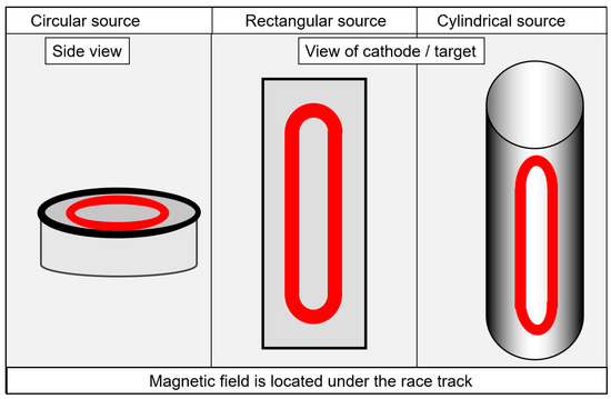
Figure 1. Schematic drawing of the circular, rectangular or tubular active evaporation surfaces, redrawn after [27], original © Vulkan-Verlag, Germany.
For the deposition of AlCr-based coatings, powder metallurgically manufactured composite targets are used most commonly. Sputtering has the advantage that composite targets in the form of segmented targets or targets with plugs of a second type of material (e.g., Cr plugs in Al target plates) can also be used [48].
Modern coating systems run in fully automatic operation. They must fulfil the following criteria with respect to high productivity and quality: high production reliability, short cycle times, high flexibility in coating types and substrate holders, easy maintenance. Additional aspects are CE (Conformité Européenne), conformity and high occupational safety standards. Environmental sustainability is also gaining importance, including the influence of factors such as energy consumption.
Of course, the basic components of the coating systems must also be optimised, e.g., vacuum pumps, power supplies, particle sources, heaters, substrate holders. In addition, all process steps including loading, pumping, heating, ion cleaning, coating, cooling, unloading and maintenance must be optimised for short cycle times and efficient operation. The choice between batch systems or inline systems depends on the use and the required flexibility. Batch systems are predominant for industrial coating applications. The system size is selected based on the expected batch size as determined by the dimensions and number of parts to be coated, but also by operating economy.
The usable volume of a batch system is defined by the interior size of the deposition chamber. Usually, coating systems are designed with a circular geometry along a central axis, allowing the rotation of substrates. The maximum useful volume therefore constitutes a cylindrical body. Small coating systems typically have a diameter of <0.5 m and a height of <0.5 m, which is adequate for small-scale series or research facilities. Medium size systems, with roughly a diameter of 1 m and a height of 1 m, are predominant in industrial production. Figure 2 shows an arc system equipped with circular arc evaporators, and a coatable diameter of 0.7 m and a height of 0.9 m. Special-purpose systems are available for large-scale manufacturing, with roughly a diameter of 1.5 m and a height of 1.5 m. Systems for oversized parts, such as broaches or plastic extrusion screws, have a coating height of up to 4.5 m.
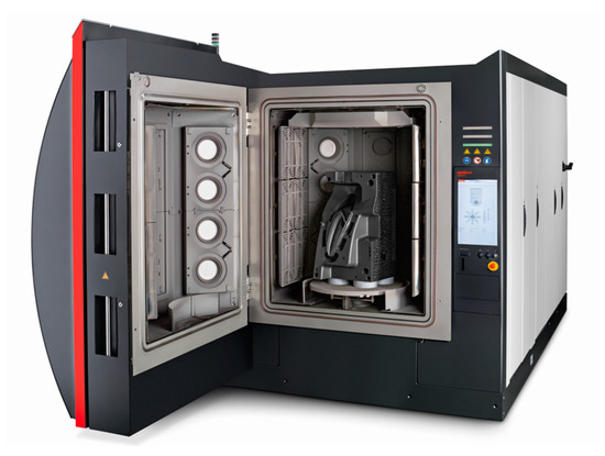
Figure 2. Medium-sized arc system equipped with circular arc evaporators, diameter 0.7 m, height 0.9 m, courtesy of Oerlikon Balzers.
CrAl-based and AlCr-based coatings deposited by arc evaporation processes or by magnetron sputtering are widely used for cutting tools, moulds, dies and for various components. The success of these coatings with their predominantly fcc structure is due to their outstanding mechanical and tribological properties (such as high hot hardness, good abrasive and sliding wear resistance) combined with high oxidation and corrosion resistance. The present chapter highlights selected basic coating properties.
To begin with, an important remark must be made on the way the coating composition is reported in papers. A full compositional characterisation, including metallic and non-metallic elements as well as impurities such as oxygen, is the most complete, but is not always reported. Several publications neglect the stoichiometric aspects, the deviation of coating composition from the cathode/target composition, and the incorporation of residual gas components. Sometimes, only the cathode/target composition or only one of the values Al/Cr or Al/(Al + Cr) are given, presumably because methods such as EDS are most suited for the characterisation of metallic and heavy elements. Many papers state that the coatings consist stoichiometrically of 50 at.% metallic and 50 at.% non-metallic elements, and they are simply described as (Al1−xCrx)N.
One positive example is described for arc-deposited coatings using cathodes of Al70Cr30. The coating was characterised by XPS as having Al 33.1 at.%, Cr 15.8 at.%, N 48.1 at.%, and O 3.0 at.%. The metallic content is thus 48.9 at.% and the non-metallic content is 51.1 at.%. The ratio Al/(Al + Cr) is 0.68, meaning 68 at.% of the metallic content is Al. This corresponds to a deviation of 2 at.% from the cathode material. The Al/Cr ratio in the coating is 2.09. The coating contains oxygen from the residual gas. The coating is slightly over-stoichiometric [58]. The total formula has to be (Al1−xCrx)(N1−wOw) plus the stochiometric ratio (Al1−xCrx)/(N1−wOw). Unfortunately, however, detailed compositional data are not reported in many publications.
As a guide for the reading of coating compositions, the following terminology is used throughout this paper.
If only the cathode composition is given and the stoichiometry in the coating is assumed to be equivalent to the cathode composition, the coating is described as (Al(100−x)Crx)N with 100 in at.%, e.g., (Al70Cr30)N.
If the metallic elements (and metalloids) were measured, but only a general statement about the stoichiometry is made, the coatings are described as (Al(100−x)Cx)N with 100 in at.%, e.g., (Al70Cr30)N.
If both metallic elements (and metalloids) and the N, O (and C) content were measured, all values are given as AlxCryNuOw, where x + y + u + w = 100 at.%, e.g., Al33Cr16N48O3.
A schematic diagram of different basic crystal structures as a function of the Al portion of the coating’s metallic content in at.% is shown in Figure 3. It should be mentioned that in publications, the formula Cr1−xAlxN or Al1−xCrxN is sometimes used for the same coating in dependence on the Al content. Nowadays, the most commonly used terminology in industrial applications is the short name (AlCr)N for Al-rich coatings. The authors suggest that coatings with a chemical composition in at.% of Cr > Al should be named (CrAl)N. If Al > Cr, then the coating should be named (AlCr)N. (CrAl)N coatings always have an fcc crystal structure. This structure type is also referred to as B1, a NaCl structure or c in certain publications, depending on the convention. With increasing Al content, a phase evolution to an hcp crystal structure takes place, which is also referred to as B4, a ZnS-type structure, wurtzite, w, h or hcp in publications. In the following, fcc and hcp will be used.
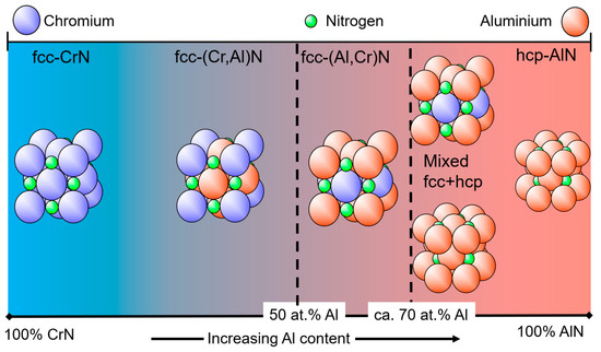
Figure 3. Schematic diagram showing the basic crystal structure of (CrAl)N and (AlCr)N coatings as a function of the Al content.
XRD investigations of rf-sputtered coatings have shown that at 57 at.% Al, a pure fcc structure was obtained, while at 75 at.% Al, the hcp structure was observed. The transition range between fcc and fcc + hcp was in the range of 57 at.% < Almax < 67 at.% [49]. With pulsed closed-field magnetron sputtering, the formation of hcp phases was observed at an Al content of 64 at.%, whereas fcc phases were detected at up to 60.9 at.%, giving a transition range of 60.9 at.% < Almax < 64 at.% [59]. A systematic experimental investigation of (CrAl)N and (AlCr)N coatings synthesised using the cathodic arc method showed that the crystal structure changed from a pure fcc structure to a mixed-phase structure of fcc and hcp at an Al content of about 60–70 at.% of the metal content in the cathodes [60], whereas an fcc structure was observed at up to 71 at.% in the coating by the authors of [61].
The reported different maximum Al contents for the X-ray-diffraction-measured pure fcc phase differ over a range of about 60–70 at.%, as shown in Table 1.
Table 1. Maximum Al content for pure fcc phase generation measured by X-ray diffraction for arc-deposited and sputtered coatings.
| Deposition Method | Source Composition (Targets/Cathodes) |
Pure fcc Phases by X-Ray at Al [at.%] Coating or Source | Fcc + hcp Phases by X-Ray at Al [at.%] Coating or Source | Range of Transition Almax [at.%] |
Reference |
|---|---|---|---|---|---|
| RF sputtering | Al and Cr targets | Coating 57 at RT 56 at 300 °C |
Coating 75 at RT 67 at 300 °C |
Coating 57 < Almax < 67 |
[49] |
| RF/DC sputtering | Al and Cr targets | Coating 63 at 300 °C |
- | 63 < Almax | [51] |
| Pulsed CFUBM sputtering |
Al and Cr targets |
Coating 60.9 at 175 °C |
Coating 64 at 175 °C |
Coating 60.9 < Almax < 64 |
[59] |
| Arc | Alloyed cathodes | Cathodes 60 at 600 °C |
Cathodes 70 at 600 °C |
Cathodes 60 < Almax < 70 |
[60] |
| Arc | Alloyed cathodes | Coating 70 at 500 °C TEM traces hcp |
- | Coating 70 < Almax |
[62] |
| Arc | Alloyed cathodes | Coating 71 at 450 °C |
Coating 75 at 450 °C |
Coating 71 < Almax < 83 |
[61] |
| Arc | Alloyed cathodes | Coating 71 at 450 °C |
Coating 75 at 450 °C |
Coating 71 < Almax < 75 |
[63] |
| DC sputtering | Segmented target |
Coating 70 at 400 °C |
- | Coating 70 < Almax |
[64] |
| DC sputtering | Alloyed targets |
Targets 1 70 at 500 °C |
- | Targets 70 < Almax |
[65] |
| Arc | Alloyed cathodes | Coating 70 at 500 °C |
Coating 82 at 500 °C |
Coating 70 < Almax < 82 |
[66] |
The deposition process itself (source properties, parameters) has an influence at the maximum Al concentration on whether a pure fcc phase is obtained using X-ray diffraction, as will be shown for arc evaporation in Section 3.4.
Taking measurement uncertainties into account, a well-accepted maximum critical value of the transition is about 70 at.% Al [61][62][63][64][65][66]. It should be mentioned that coatings with Al contents of 65–70 at.% might contain some traces of hcp phases, which may, however, be difficult to detect using XRD. For example, this effect was observed with SAED (Selected Area Electron Diffraction) measurement of (AlCr)N coatings deposited using arc evaporation from cathodes of Al70Cr30 on sapphire [62]. The critical value of the transition from fcc to the mixed fcc plus hcp structure also depends slightly on the deposition conditions, influenced, for example, by the evaporator magnetic field set-up analogously to AlTiN [9], but bias and deposition pressure also have an influence on the “fine” structure in the area of the transition [45].
Figure 4 shows experimental results for the hardness and lattice parameters of arc-deposited (CrAl)N and (AlCr)N coatings [60][61]. Both studies show a hardness increase of about 60% compared to CrN for fcc-structured coatings in the range of Al 60–70 at.%. The differences in the absolute values are likely related to different deposition techniques and hardness measurement conditions. Furthermore, in the region of the mixed-phase structure of fcc + hcp at high Al-content, the hardness is equivalent to CrN. The lattice parameters decrease from 0.415–0.416 nm (CrN)) to 0.413 nm in the region of Al 60–70 at.%.
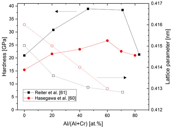
Figure 4. Hardness and lattice parameters of (CrAl)N and (AlCr)N coatings versus Al content deposited by cathodic vacuum arc, redrawn after [60][61], original © Elsevier.
Lattice parameters for (CrAl)N, (AlCr)N, CrN and AlN coatings calculated ab initio are shown in Figure 5 and are compared with experimental XRD results [63]. The good fit of the calculated and the experimental data shows how well the basic properties of AlCr-based coatings can be calculated.
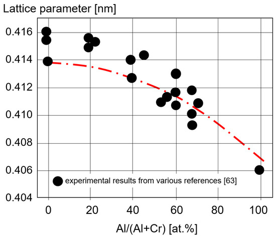
Figure 5. Lattice parameter calculated ab initio for CrN, (CrAl)N, (AlCr)N, and AlN coatings and experimentally measured XRD values, redrawn after [63], original © Elsevier.
The thermal expansion coefficients (TECs) of fcc-structured (Cr,Al)N and (Al,Cr)N coatings deposited by sputtering were investigated using synchrotron X-ray diffraction at up to 600 °C [65]. It was shown that the thermal expansion coefficient increases with an increasing Al content, from about 7 × 10⁻⁶/K at room temperature to 10 × 10−6/K at 600 °C, see Figure 6. Higher mean values of 14.5 × 10⁻⁶/K were reported both for sputtered and arc-deposited (Al70Cr30)N coatings at room temperature [43]. A fair general estimate is thus (10.5 ± 3.5) × 10−6/K.
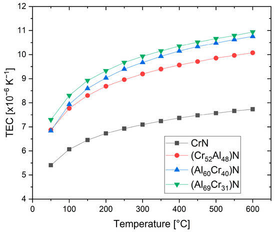
Figure 6. Temperature-dependent thermal expansion coefficients (TECs) of (CrAl)N and (AlCr)N coatings derived from synchrotron experiments, redrawn after [65], original © Elsevier.
Figure 7 shows the thermal conductivity of (Ti50Al50)N, (Al66Ti34)N, and (Al70Cr30)N coatings [67]. The thermal conductivity is temperature-dependent and it is interesting to note that the thermal conductivity of (Al70Cr30)N drops at about 200 °C and, in the temperature range of 250–450 °C, is significantly lower than that of (Al66Ti34)N. The thermal properties of Cr25Al20.5Si4.5N50 coatings were measured using pulsed photothermal radiometry. A very low thermal conductivity of ca. 2.75 W/mK at room temperature and 3.5 W/mK at 400 °C was found [68]. PVD coatings exhibit a certain anisotropy of thermal conductivity perpendicular and parallel to the direction of growth. This effect is particularly pronounced for multilayer coatings. When engineering the thermal properties of a coated part, not only the intrinsic thermal conductivity of the coatings, but also the concentration and dimension of different growth defects, e.g., holes and droplets, must be taken into account [69].
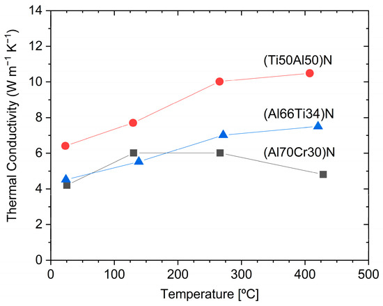
Figure 7. The temperature dependence of thermal conductivity for arc-deposited (Ti50Al50)N, (Al66Ti34)N and (Al70Cr30)N coatings, measured using the picosecond thermal reflection method, redrawn after [67], original © Elsevier.
A two-probe measurement method was used to estimate the surface resistance as a function of the Al/(Al + Cr) ratio for arc-deposited coatings. It can be seen in Figure 8 that the electrical resistivity increases sharply with the Al portion of the metallic content in at.% [19].
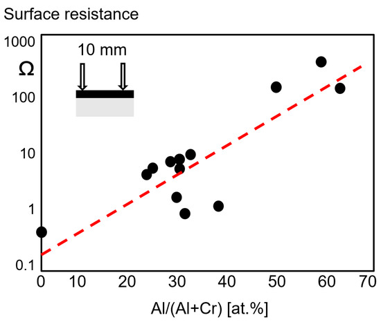
Figure 8. Surface resistance as a function of the Al content of fcc-(Cr,Al)N and fcc-(Al,Cr)N arc-deposited coatings, redrawn after [19], original © Elsevier.
Ab initio calculations have shown that the Poisson’s ratio drops from about 0.27 for low Al contents to about 0.2 for an Al content of 70 at.% [70]. Figure 9 shows the ab initio calculated Young’s moduli (E) as a function of the Al content for fcc (Al,Cr)N [70][71]. Selected Young’s moduli measured by nanoindentation from [64][71] have been added.
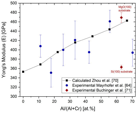
Figure 9. Ab initio calculated Young’s moduli E and experimentally obtained indentation moduli (black symbols) for different Al concentrations in fcc-(Cr,Al)N and fcc-(Al,Cr)N coatings, redrawn after [70], original © AIP Publishing, data from [64][71].
The Young’s modulus increases with an increasing Al content. The same relative tendency, but with lower absolute values, was experimentally shown in [43]. The calculated values are in good agreement with measured nanoindentation moduli [64][72]. The Young’s modulus of (AlCr)N coatings drops significantly when the mixed-phase structure fcc + hcp is reached [43], as well as for Si-alloyed (AlCr)N coatings of, for example, Al33.4Cr18.3Si2.3N46O0.7 [73]. It should be noted that large variations of measured E values for fcc-(Al,Cr)N coatings have been published for coatings of nearly the same composition, for example, from 300 GPa (Al/(Al + Cr) content of 68 at.%) [73] to 469 GPa (Al/(Al + Cr) content of 63 at.%) [71]. Different sample conditions (thickness and substrate) and measurement systems themselves will influence the measured value.
In addition to the chemical composition, the Young’s modulus is also dependent on the grain size (grain boundary fraction), the compressive stress state, and the texture. A variation from 363 to 469 GPa was measured for Al28.4Cr 18.6N55 in different coating states. The high value was measured for a highly 100-oriented coating deposited on MgO (100) substrates [71]. Thus, a relatively wide variation of experimental results, besides the measuring conditions, must be anticipated.
The fracture toughness KIC of sputtered Al28.4Cr18.6N55 was measured by micromechanical bending tests at 1.3 ± 0.1 MPa √ m, which is lower than that of TiN at 2.0 ± 0.1 MPa √ m related to domain size effects, but it is possible to raise this in a superlattice combination of the two materials [71].
The thermal stability of arc-deposited (CrAl)N and (AlCr)N coatings has been investigated through heat treatment in an Ar atmosphere with a hold time of 2 h at temperatures between 600 and 1300 °C in combination with XRD analysis [61]. The fcc structure was found to be stable up to 800 °C. Three reactions were observed sequentially for the (AlCr)N-system:
Transformation of fcc (Al,Cr)N to hcp (Al,Cr)N at the grain boundaries first [74],
Segregation of Cr2N,
Segregation of pure chromium.
Above 900 °C, the entire coating transforms to a mixed-phase structure. No phase transformation occurred in the hcp-AlN coatings, as they were already in their thermodynamically stable state. This is shown schematically in Figure 10.
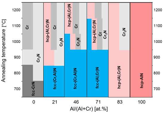
Figure 10. Schematic diagram of phase stability for (CrAl)N and (AlCr)N as determined by XRD spectra after annealing at different temperatures, redrawn after [61], original © Elsevier.
The effect of the annealing on the hardness of the same coatings was characterised as well, see Figure 11.
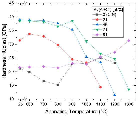
Figure 11. Microhardness for (CrAl)N, (AlCr)N, CrN and AlN coatings after annealing at different temperatures, redrawn after [61], original © Elsevier.
The highest hardness was shown for (Cr54Al46)N and (Al71Cr29)N, and was retained up to 800 and 900 °C, respectively. The subsequent drop in hardness at higher annealing temperatures is correlated with the phase decomposition [61].
The influence of the coating stress at the decomposition temperature was investigated by varying the deposition temperature. The coating deposition was performed by arc using Al70Cr30 cathodes. It was shown that the decomposition temperatures of the metastable fcc-(Al63.5Cr36.5)N phase depends significantly on the stress level in the coatings. The decomposition process starts at the same compressive stress level of around 4.3 GPa for all coatings that were investigated [75].
Figure 12 shows a comparison of the hardness after annealing at high temperatures for different commercial hard coatings, showing that the (Al70Cr30)N coating has the highest hot hardness for temperatures exceeding 950 °C.
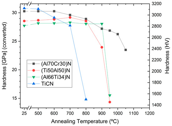
Figure 12. Hardness after annealing of commercial TiCN, (Ti50Al50)N, (Al66Ti34)N and (Al70Cr30)N coatings on cemented carbide.
The oxidation behaviour of PVD hard coatings is an important property for applications such as dry high speed cutting and high temperature stressed components such as turbochargers. In a study of Cr-rich (CrAl)N sputtered coatings (Cr/Al = 2.94), a relatively small Al content (Cr44Al15N40 at.%) improved the oxidation stability compared to CrN [15]. The first publication about the oxidation characteristics of arc-deposited coatings (AlCr)N with a Al/Cr ratio > 0.5 showed a lower oxidation rate in comparison with CrN [19], as has been confirmed in further studies [51][61][76][77]. Oxidation tests of (CrAl)N and (AlCr)N coatings deposited by activated reactive evaporation showed excellent behaviour [32]. The authors stated that the investigated (CrAl)N and (AlCr)N coatings exhibited significantly better oxidation behaviour than TiAlN coatings, which has been confirmed in further studies [40][78]. A systematic comparison of the oxidation behaviour of arc-deposited (AlTi)N and (AlCr)N coatings, including long time exposure, was performed in [40]. It was shown that the oxidation resistance of both coatings improved with an increase in the Al content. The oxidation resistance of (AlCr)N coatings was significantly superior to that of (AlTi)N coatings. Figure 13 shows the oxide layer thickness of CrN, (CrAl)N and (AlCr)N coatings after annealing in the temperature range of 800 to 1000 °C in an ambient atmosphere for 30 min in 50 and 100 °C intervals. The addition of 20 at.% of Al to CrN deferred the start of oxidation by 100 °C and reduced the oxidation rate. The onset temperature for oxidation increased and the oxidation rate decreased with a further increase in the Al-content up to 71 at.% Al. At a higher Al content, significantly decreased oxidation resistance was detected for a coating with 83 at.% Al and for AlN. Oxidation then starts already at 800 °C. These coatings already have an hcp structure. The negative influence of the hcp structure on the oxidation resistance was confirmed by [79].
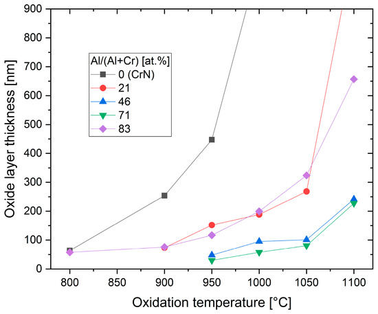
Figure 13. Thickness of oxide layer for CrN, (CrAl)N and (AlCr)N coatings after annealing at different temperatures in an air atmosphere, redrawn after [61], original © Elsevier.
A model of the oxidation behaviour for both the onset temperature and the oxidation rate depends on the coating composition and the related phase structure, as described above. However, it was observed in general that Cr and Al ions diffuse to the surface, forming a dense oxide layer acting as a diffusion barrier, thereby limiting the inward diffusion of oxygen [32][76][80]. The onset of oxidation of fcc (Cr,Al)N and fcc (Al,Cr)N always starts with the dissociation to h-Cr2N and nitrogen in the coating. The presence of thermally stable Al–N bonding in the fcc-(Cr,Al)N structure can suppress the reduction of nitrogen in the coating. A dense (CrAl)2O3 or (AlCr)2O3 oxide layer (either amorphous or crystalline) is formed at an early stage of oxidation [76]. This can act as an effective diffusion barrier hindering the inward diffusion of the oxygen. All further reactions are influenced by the Al content at a given temperature.
It should be mentioned that there are several ways to increase the oxidation stability of (CrAl)N and (AlCr)N coatings, e.g., by means of synergistic alloying of the coatings with small amounts of Si [81], see also Section 4.4. By way of illustration, Figure 14 shows the excellent oxidation resistance of (Al70Cr30)N coatings in comparison to industrial-standard PVD coatings.
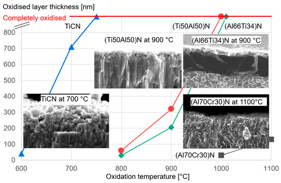
Figure 14. Thickness of the oxide layer as a function of the oxidation temperature for different industrial-standard PVD coatings.
The tribological properties of (CrAl)N and (AlCr)N depend not only on the coating properties, but also on the tribosystem itself (e.g., counterpart, lubrication, temperature, loads).
The dry friction value of (AlCr)N coatings against steel is slightly higher than that of CrN at ca. 0.65 [19], as measured using the pin–on-disc method against hardened bearing steel, 100Cr6. A friction value for (AlCr)N of about 0.5 was reported for AISI4340 as a pin [82]. The friction value at low load (5 N) was similar to that of (TiAl)N, whereas at high load conditions (20 N), (AlCr)N displayed a significantly lower friction coefficient. The superior tribological behaviour, namely a low wear rate and low friction, of an (AlCr)N coating against AISI 4340 steel is associated with the higher proportion of distinct (dispersive-polar) interactions, as evidenced by the measured surface energies. (AlCr)N and (TiAl)N coatings have a high polar component of 19.8 and 15.4 mJ/m2, and a low dispersive component of 2.9 and 6.5 mJ/m2, respectively, while the AISI 4340 steel presented a similar proportion between the polar, 14.3 mJ/m2 and dispersive 13.5 mJ/m2 components [82]. Measurement of the dry friction of (AlCr)N coatings by pin-on-disc against austenitic stainless steel (DIN1.4301, AISI 304, hardness 274 HV1) showed a friction value of 0.85 at room temperature, which dropped to about 0.6 at higher temperatures [83].
The coefficient of friction measured by pin-on-disc tests against Al2O3 balls for (CrAl)N and (AlCr)N coatings of different Al contents showed a friction coefficient of about 0.6 at room temperature, independent of the Al content [83]. The friction value increased for 500 °C and dropped to 0.6 again at 700 °C, and was also nearly independent of the Al content. Figure 15 shows the decreasing abrasive wear rate with increasing Al content for all investigated temperatures [83].
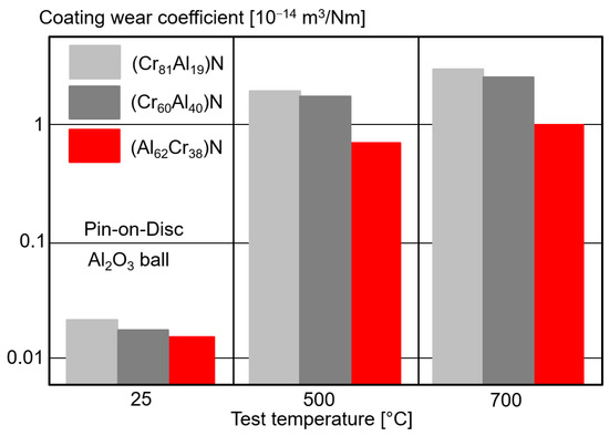
Figure 15. Wear coefficient of (CrAl)N and (AlCr)N coatings with different Al contents by pin-on-disc tests compared to Al2O3 balls for different test temperatures, redrawn after [83], original © Springer Nature.
The dry tribological properties of arc-deposited (Al70Cr30)N, (Al67Ti33)N, and CrN coatings against a Si3N4 ball as the counterpart showed friction values of 0.73, 0.79, and 0.77 at the end of the test, respectively [84]. A special effect related to the wear rate was observed. The highest wear rate was measured for (Al67Ti33)N, but CrN had a slightly lower wear rate than (Al70Cr30)N. The authors claim this is caused by the tribological oxidation behaviour, which has a great influence on the wear mechanism and the debris removal behaviour of the coatings.
(CrAl)N and (AlCr)N coatings synthesised using PVD processes display a rich variety of microstructures, from fine-grained morphology up to coarse columnar structures, which make different (AlCr)N coatings suitable for many diverse application areas. This section focuses on (AlCr)N coatings, though similar effects are also valid for (CrAl)N coatings. The relationships between the deposition parameters and the coating morphology are summarised in generic structure-zone diagrams [85] to provide guidelines that can be applied for (AlCr)N coatings in general. The deposition conditions can also be used to control the stress state of the coatings [86], which often is an important part of engineering coatings and in adapting them to different use cases and requirements. For example, thick coating layers are at risk of peeling off if the stress state is too high, while high compressive stresses can be advantageous in interrupted cutting operations. The stress state has also been pointed out as a key determining factor for thermal stability and decomposition pathways [75].
The effect of bias voltage on the stress state and coating properties of (AlCr)N coatings deposited using Al60Cr40 targets has been investigated systematically [87]. Increasing the bias voltage led to higher levels of compressive residual stresses as a function of the increased ion bombardment, up to a threshold in the range of 100 V, see Figure 16. Further higher bias values reduced the overall stress state, which was attributed to the annihilation of defects and stress relaxation. A concurrent reduction in grain size, the lattice parameter and a modified preferential orientation in XRD from (200) to a mixture of (200) and (111) were also observed as an effect of increasing the bias [87].
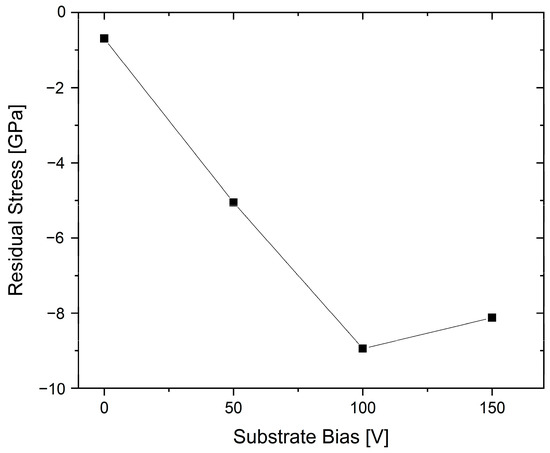
Figure 16. Compressive residual stress versus the bias voltage for arc-deposited (Al60Cr40)N coatings, redrawn after [87], original © Elsevier.
Similar trends for texture and increased hardness with bias were also reported for coatings deposited using Al70Cr30 and Al75Cr25 cathodes. Coatings with a higher Al content, deposited using Al85Cr15 and Al90Cr10, formed dual-phase structures at bias voltages higher than 40 V [66]. The influence of phase structure on the stress state has been exemplified in the direct comparison of (Al80Cr20)N coatings, which had lower compressive stress values relative to (Al70Cr30)N. This effect was attributed to stress relief through the presence of hexagonal phases in the former case [88].
The stress state of (AlCr)N coatings can also be influenced by alloying elements. For example, B-alloyed coatings with 2.3–9.1 at.% of B have been demonstrated to have lower compressive state levels compared to unalloyed coatings. The B-alloying also caused grain-size refinement and an increase in hardness attributed to a combination of solid solution hardening and Hall-Petch hardening [89]. Further aspects of alloying will be discussed later in this review.
Surface morphology, and in particular the density of macroparticles in arc deposition processes, can be influenced by the deposition pressure where fewer macroparticles are generated and smoother coatings are obtained at higher pressure [90][91][92], see also the example in Figure 17. This effect can be rationalised through a higher degree of poisoning on the target surface at an elevated pressure. Columnar morphology is typically achieved over a large process window of deposition pressures, though with variation in the column width. This is illustrated in Figure 17a–d. Further reported effects of deposition pressure include increased hardness and an influence on the phase structure [91][92].
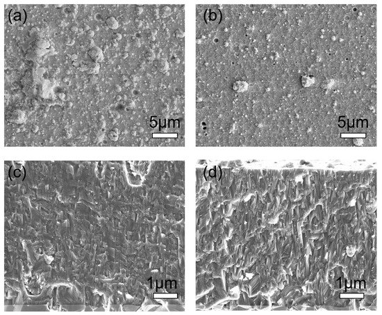
Figure 17. Surface and cross-sectional morphology of (AlCr)N monolayer coatings deposited for (a,c) at 2.5 Pa N2 and for (b,d) at 7.5 Pa N2, for illustration of relative trends.
The structure of arc-deposited AlCr-based coatings depends not only on the cathode composition, process temperature, substrate bias potential, arc current and reactive gas pressure, but also on the arc source design, in a manner that is similar to the case of AlTi-based coatings [9]. The influence of the magnetic set-up was investigated in one coating process using two arc sources, both equipped with Al70Cr30 cathodes, strong and weak magnetic fields, respectively [93]. Figure 18 shows the differences between the two deposited coatings by means of XRD investigation, SEM cross-section and hardness measurement. The coating properties vary significantly. Although EPMA (Electron Probe Micro Analysis) measurements showed a lower Al/(Al + Cr) content, a minor hcp face is visible in the coating deposited by the weak field, which explains the finer growth structure (smaller grains) of the coating. Furthermore, the coating deposited with the weak field contains less nitrogen and the hardness is about 30% lower compared to the coating deposited with strong magnetic fields.
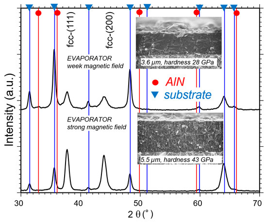
Figure 18. Phase formation of coatings deposited with pm cathodes Al70Cr30 for two evaporators with different magnetic field set-ups [93].
Dual-phase coatings with Al concentrations of more than 70 at.% have been reported as monolayer coatings [88][90][94][95], as well as multilayers [66][96]. The coatings are characterised by relatively low hardness compared with fcc (Al,Cr)N, lower oxidation resistance than fcc (Al,Cr)N with a high Al content, but also with the positive effect of exhibiting lower stress.


