The SPM system consists of four main components, namely, the body of the buoy, the anchoring and mooring components, the fluid transfer system and the ancillary elements. Static legs linked to the seabed underneath the surface keep the buoy body in place. Above the water level, the body has a spinning portion that is attached to the offloading/loading tanker. A roller bearing, referred to as the main bearing, connects these two portions. Due to this array, the anchored tanker can easily weather-vane around the buoy and find a steady position. The concept of the buoy is determined by the type of bearing utilized and the divide between the rotating and geostatic sections. The buoy’s size is determined by the amount of counter buoyancy required to keep the anchor chains in place, and the chains are determined by environmental conditions and vessel size.
1. Categorisation of SPM Moorings
CALM buoy is an application of SPM mooring systems
[1][2][3][4][5][6][7][8][9][10]. There are three categories of SPM moorings that will be looked: SPMs, CALM buoys and marine hose systems. These are based on their operational relevance to the CALM buoy system or the connecting FPSO tanker in an SPM unloading or discharging hose system, like deepwater lines, Oil Offloading Lines (OLLs), flexible riser pipes, flexible hoses, and other CALM buoy hose systems
[11][12][13][14][15][16][17][18][19][20]. To avoid failure, safety must be key for installation and (un)loading
[21][22][23]. An operation to replace or install components can be carried out to change the complete buoy hose system, like on the SBM buoy in Djeno Teminal, Congo
[24], as depicted in
Figure 1.
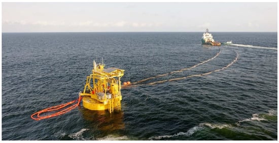
Figure 1. Full replacement operation of floating hoses, submarine hoses, hawsers and a single point mooring (SPM) buoy attached to a service offshore vessel (SOV) by a tug supply boat, located at 35 m water depth in Republic of Congo, Djeno Terminal (Courtesy: Bluewater & South Offshore
[24]).
Once the floating buoy is secured to the seafloor by moorings, next is the anchoring systems. These might be made up of ships, rigs, piles, or gravity anchors, depending on the local soil conditions. Based on the SPM classification, CALM and SALM are the two most common mooring systems for SPMs. In a CALM system, the buoy is held in place by the CALM’s anchor chain, which runs in catenaries towards anchor points slightly further away from the buoy. The SALM system is similar, with the exception that the SALM is only anchored by one anchor leg. The key advantage of a CALM buoy over a SALM buoy is it is easy to maintain. CALM buoys have been deployed in the vast majority of Marine Terminals since the mid-1990s.
2. Components of SPM System
Generally, the mooring lines, connectors, and anchors make up a mooring system. The mooring wires can also be used to connect buoys and clump weights. A mooring line can be made of a variety of materials, such as chains, fiber ropes, or wire ropes.
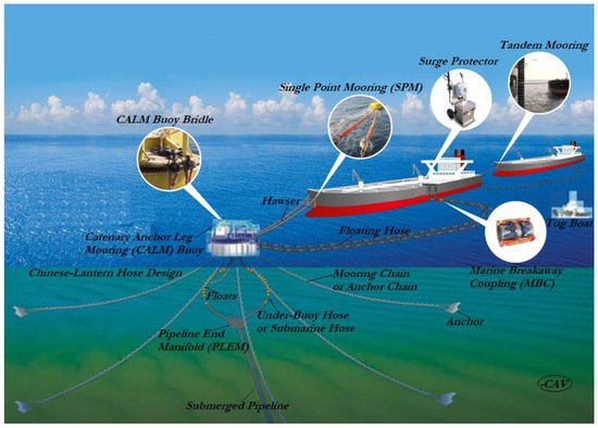
Figure 2 represents a CALM buoy system, three mooring configurations and various components, adapted from
[25]. The three mooring configurations seen on
Figure 2 are the Chinese lantern configuration, single point mooring (SPM), and tandem mooring.
Figure 2. Catenary Anchor Leg Mooring (CALM) buoy hose system showing Chinese lantern configuration, single point mooring (SPM), and tandem mooring. It shows the Marine Breakaway Coupling (MBC), anchor, mooring chain or anchor chain, floating hose, under-buoy hose or submarine hose, buoyancy floats, CALM buoy, hawsers, surge protector, tug boat, submerged pipeline, pipeline end manifold (PLEM) and the CALM buoy bridle. (Adapted with permission
[25]).
Figure 2 also shows various components like the Marine Breakaway Coupling (MBC), floating hose, under-buoy hose or submarine hose, buoyancy floats, CALM buoy, surge protector, tug boat, submerged pipeline, pipeline end manifold (PLEM), hawsers, CALM buoy bridle, anchor, and anchor chain or mooring chain.
Harnois
[26][27] provided a comparison of various mooring line materials. The inertia, elastic stiffness, and damping of a mooring line are affected by the material used. An anchor’s purpose is to secure a mooring line to a fixed place on the bottom. The ability to resist high, horizontal, and in some cases vertical loads in a specific seabed type (soft to hard), cost-effectiveness, and ease of installation are the major requirements for an anchor. There are several types of anchors available, including dead weight, drag embedment, pile anchor, and plate anchor. It is noteworthy to add that the use of hawser is dependent on the size of the vessel to be anchored to the buoy, as hawser systems can use one or two ropes, as depicted in
Figure 1 and
Figure 2.
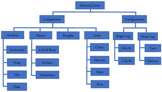
A mooring system is made up of many materials and components that are organized in a specific way, as shown in Figure 3. The other SPM components are as follows:
Figure 3. Illustration of the components and configurations for a mooring system. [Illustration design: by Author1].
-
The access to the buoy deck is provided by a boat landing;
-
The buoy is protected by fenders;
-
The material handling equipment includes lifting and handling equipment;
-
Maritime visibility aids and a fog siren are used to keep moving vessels alert and attentive;
-
The navigation aids or other equipment are powered by the electrical subsystem;
-
The sources of power systems are batteries and solar systems. While the batteries are replenished on a regular basis, the solar power systems employ sun-sourced renewable energy and maintain the charge in the battery packs, for electrical power;
-
A hydraulic system can be added for remote operation with PLEM valves, if needed.
3. Components of CALM Buoy System
The Catenary Anchor Leg Mooring (CALM) buoy system has a buoy with a pivot, called the turntable. This rotates around the vertical axis of the pivot, as the tanker is moored to it. The floating hose is also connected to the turntable, at an angle through the hose manifold. The elastically moored buoy of radius a is acted upon by a wave train of irregular waves and wave height H progressing in x-direction, as illustrated in Figure 1. The turntable on the mooring buoy can spin around its vertical axis. The tanker is moored to the turntable and is connected to the floating hose strings that are also attached to the turntable. Due to the forces imposed by the currents and waves, the entire system can freely rotate, which is termed weather-vaning. Figure 1 and Figure 3 show Catenary Anchor Leg Mooring (CALM) buoy systems. Basically, there are three CALM system mooring components, namely, the anchors, the chain anchors and the chain stoppers. The anchors are used to hold things together, including the piles or gravity anchors for connecting the seabed with the mooring chain. The most common chain anchors are systems with either six or eight anchor chains. The third component is the stoppers for chains, which are for connecting the buoy with the mooring chains. The anchor chains help to keep the buoy in place. The fluid is transferred to the submarine hose strings via a swivel, which links to the undersea pipeline via the pipeline end manifold.
4. Different Mooring Configuration
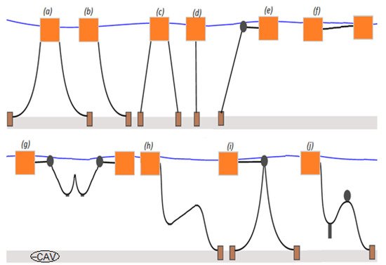
There are other types of offshore mooring systems, aside SPM. Based on the mathematical modeling, HMs and MMs, considering SPMs for bonded marine hoses, have been developed over 45 years based on earlier works on point moorings and simple floating buoys. The application of offshore hoses has also led to advances in different mooring systems used in fluid transfer, as seen in Figure 4.
Figure 4. Configurations for mooring lines showing: (a) multi-catenary taut; (b) catenary; (c) taut; (d) spread; (e) SALM; (f) ship-to-ship catenary; (g) weight-added connection; (h) Lazy-S, (i) CALM; and (j) Steep-S. [Sketch design: by Author1].
Moorings are also applied on shipping vessels for other oil field operations like CO
2 oil recovery
[28]. Several studies assessed mooring statics and dynamics for CALM buoy, as well as with attached hoses, which were considered as a single point mooring (SPM) terminal
[29][30][31][32][33]. The design of each hose-mooring system considers different loadings, predictive motion responses with structural statics/dynamics
[34][35][36][37][38][39][40][41][42][43][44], and governing theories on the hydrodynamics of floating structures
[45][46][47][48][49][50][51][52][53][54]. In addition, the design of FOS is based on different industry standards
[55][56][57][58][59]. The application of a mooring configuration is based on the application requirement, the type of (un)loading operation, and the environmental conditions. Some of these mooring applications require floating, catenary, and reeling hoses, while others require submarine hoses.
5. Review on Physical Models on Hoses and SPMs
The selection of hose systems for single point mooring (SPM) systems has been described by Ziccardi and Robbins
[60]. Setting up buoys in low-tide areas was discussed as the authors also wanted to stimulate more hose and flexible rubber pipeline designs and applications. They studied the SPM deployments at Tokyo Bay’s Hakozaki and Koshiba terminals. They also included a timeline of hose design and trends. They claimed that the basic designs of under-buoy hoses and floating hoses are comparable. The strong crush resistance of sub-surface hoses, on the other hand, was shown to be dependent on the water depth. This was accomplished by increasing either the wire’s area or the diameter of the helical wire, or both. The rated operating pressure was found to be 5 to 6 times the design burst pressure. They highlighted the abrasion and abuse that the floating hoses attached to the tanker from the buoy were subjected to. They came to the conclusion that developing flexible rubber lines that could sustain high operating pressures and external crush, particularly in severe environments, was critical. The hose system for an SPM terminal was also reliant on both the operational and environmental conditions, according to the report. Physical tests are also used to develop environmental wave spectra, such as the Joint North Sea Wave Project (JONSWAP) wave spectrum and regular wave types like Airy waves
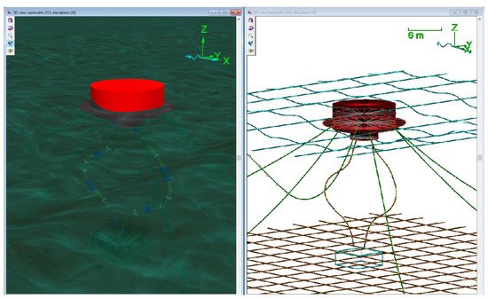
[61][62][63][64][65]. Typical recent numerical model of CALM buoy model conducted in Orcina’s Orcaflex by the authors can be seen in
Figure 5.
Figure 5. CALM buoy model using Chinese lantern configuration under an ocean environment in Orcaflex 11.0f, showing a shaded view and a wireframe view. [Model design: by Author1].
The operational requirements, such as the system’s working pressure, necessitated the transportation of well-specified products with an adequately defined nature. They listed several factors that must be considered when determining the length of hose strings in hose designs, including mean water depth, tide depth (low/high), maximum wave height, buoy position relative to pipeline header, maximum mooring distance, rated working pressure, desired throughput, and product(s) to be transported. They advised that the ultimate design of the under-buoy system should ensure that the hose does not come into direct contact with the seabed of the moored ship under high tide conditions. They looked at the primary design criteria for SPM hoses, underbuoy system, floating hose systems, float sinks, hose designs, and hose diameters, and encouraged greater research from hose manufacturers, using the two case studies that were employed by the US military on unloading from SPM tankers.
Earlier investigations on marine hoses depended on some lengthy calculations and experiments. Brady et al.
[66] with the help of Shell B.P Petroleum Company of Nigeria Limited, built a test apparatus that was connected to 60.96 cm (24 inches) hoses attached to a CALM buoy off the coast of Nigeria. A Medilog 4–24 small four-channel cassette recorder, a 4–366 pressure transducer, and a Beaulieu S.P 16 mm Cine camera with a lens width of 5.9 mm were also included in the setup. To measure the strains on the hose of a monobuoy, a strain-gauge measuring spool was installed between the buoy manifold and the first-off buoy hose. They claimed that the hoses closest to the buoy have a lower life expectancy because they carry the majority of the hose stresses. Correlation of the measured loads was achievable using the statistical method described for calculating the 60 s recordings and visual records of the sea conditions. However, this was limited due to a lack of environmental data. Rather than the trial-and-error method employed previously, this technology enabled the investigation of the forces on buoy hoses. They came to the conclusion that the hose problem was primarily caused by fatigue rather than high loads. As a result, increasing the hoses’ strength will improve their performance. SPM terminals were subjected to model testing by Pinkster and Remery
[67]. The test results were also used to describe SPM terminal features and hose phenomena found in CALM and SALM mooring systems. They also stressed the need for selecting the appropriate scale for model tests. They cited water depth, the accuracy of the results, and the capacity to generate the needed wave height and period at a certain scale in the basin as critical variables. Water depth, current, wave generators, and wind are some of the variables that can be modified to affect environmental conditions. They also went over the model testing technique, measurements, and analysis in detail. They concluded that nonlinearities were exploited in the construction of the equation of motion, which was then integrated in small time increments step by step. Additionally, based on uncertainties in the prototype’s drag coefficients, the inaccuracies in the estimates of the findings obtained from the model tests due to scale effects should be applied without modification. There was additional discussion of the Pierson–Moskowitz spectrum, wind forces, current forces, first-order wave forces, second-order wave forces, and drag wave drifting equations. However, the methodologies for calculating these forces were not sufficiently developed for design consistency. An industry collaboration with academia was conducted on the feasibility of using geodesic IGW designs for offloading hoses, as reported in Nooij
[68]. Another important study that was carried out on the load response of offshore hoses by Lassen T. et al.
[69] involved finite element models and full-scale testing for a 20inches-bonded hose with steel end fittings. The study presents limits based on API 17K
[70] criteria for the extreme load capacity assessments. The study also included a methodology for predicting the fatigue life of bonded loading hoses’ response to applied bending, tension and pressure using a catenary configuration, with reeling loadings repeated and significantly tensioned. The study emphasized the fatigue life prediction methods, as well as the load impacts on the hose during reeling operations, for both rubber and steel parts.
6. FPSOs for Marine Hose Operations
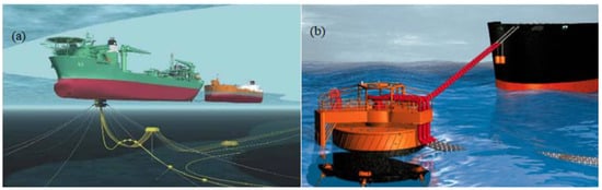
There are different types of FPSOs that are used in SPMs for transfer, loading and offloading operations. The turret systems are the most common because of their freedom of movement, ease of anchorage, and accessibility during mooring and deployment. A typical turret FPSO in catenary mooring is shown in Figure 6a, and an Offloading FPSO attached to an SPM’s CALM buoy is shown in Figure 6b. A variety of numerical models on other mooring systems can be seen in the literature and existing industry projects on marine hose, as earlier discussed.
Figure 6. Typical Floating Production Storage and Offloading (FPSO) systems showing (a) a turret FPSO with catenary moorings and (b) an Offloading FPSO attached to a CALM buoy using single point mooring by 2 hawsers and 3 floating hoses.
 +1 point