By characterisation, a marine hose is a unique type of flexible riser used in fluid transfer. By definition, a marine hose is simply a fluid transfer conduit utilised in transferring, discharging, loading, and transporting fluids from an oil well to the platform of a floating platform or a floating structure. The fluid transfer system for bonded marine hoses is dependent on floating offshore structures (FOS). Single Point Mooring (SPM) systems are component aspects of the techno-economic design and FOS operation.
1. Introduction
By definition, a marine hose is simply a fluid transfer conduit utilised in transferring, discharging, loading, and transporting fluids from an oil well to the platform of a floating platform or a floating structure
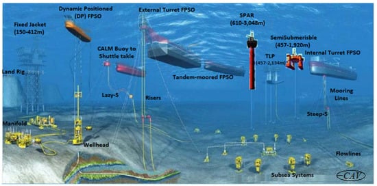
[1][2][3]. These platforms could be an FPSO (Floating Production Storage and Offloading) vessel, a CALM (Catenary Anchor Leg Mooring) buoy, a SPAR (Single Point Anchor Reservoir), a floating semisubmersible, or a TLP (Tension Leg Platform), as depicted in
Figure 1. However, due to the weight of the kill lines, marine hoses in chutes, reeling hoses on reel drums, marine risers, and other components on the deck, it is necessary to reduce the deck loads by using lighter and more sustainable materials/technologies. Thus, there is a need for lighter conduits and composite risers cum bonded marine hoses, to reduce the deck loads on CALM buoys, FPSOs and other offshore platforms (
[4][5][6][7][8][9][10][11]). The light weight makes it easier to store. Hence, it helps to create spaces on chutes, gangways, and storage racks. It also reduces the platform’s dead load.
Figure 1. Deep water facilities showing offshore platforms with the configurations for marine risers and mooring lines.
Recently, there has been a campaign in the marine industry for sustainable fluid transfer operations as one of the critical aspects of maritime and naval operations
[12]. This development is in line with the UN SDG’s goal of sustainability.
Generally, floating offshore structures (FOS) are designed to be load-bearing, with connection components for both moorings and hose-risers. Examples of FOS include the Catenary Anchor Leg Mooring (CALM) buoys or Single Anchor Leg Mooring (SALM) buoys, the shuttle tankers or Floating Production Storage and Offloading (FPSO) vessels. The connection components include the bonded marine hoses, Hose End Valves (HEVs), Marine Breakaway Coupling (MBC), and Pipeline End Manifold (PLEM). Conversely, the ancillary components used in attaching the hoses to other hose sections or the tanker/buoy manifolds include the shackles, chain pick-up, and butterfly valves.
All these connection components are utilized on the marine hose via a variety of sustainable mooring methods, such as these three formations. The first form, also known as Multiple Buoy Mooring (MBM), typically consists of the following main components: mooring system with buoys, mooring legs and anchor points, pipeline end manifold (PLEM), pipeline to shore, subsea control system, and hose string with pick-up arrangement
[12][13][14][15]. The many buoys are fastened to the seabed in a rectangular pattern with mooring lines and marine anchors, allowing safe mooring of a vessel positioned between the buoys with tug assistance. The bow of the ship is tied to the buoy surrounding it using both anchors or forward mooring buoys, while the stern is secured to the buoy around it using the stern and quarter mooring system. It keeps the ship in a fixed position and prevents it from weathervaning. The buoys serve as powerful anchor points for the vessel’s on-board mooring lines.
A launch crew takes the tanker lines one at a time and tows them to the numerous mooring buoys as soon as the tanker has approached into position with the help of tugs. The second form is the Single Point Mooring (SPM), which is an anchored loading buoy that acts as a mooring point and an interconnection for tankers loading or discharging liquid or gas contents.
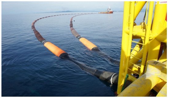
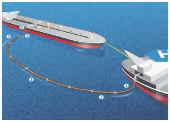
Figure 2 is a typical SPM terminal showing an SPM buoy and the Trelleborg’s floating hoses. The primary function of this SPM buoy is to maintain the vessel’s location concerning the buoy, keeping it in a stable position while allowing the vessels’ swinging responses to the ocean and wind
[12].
Figure 2. SPM buoy hose system from the buoy to the shuttle tanker on an SPM Terminal (Provided by Trelleborg for this paper, and used with permission, Courtesy: Trelleborg).
2. Sustainable Fluid Transfer at SPM Mooring Terminals
2.1. Sustainable Fluid Transfer Operation
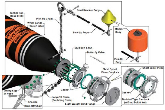
The fluid transfer system is at the heart of every SPM, as shown in Figure 2. The design parameters for this system mainly considers its safety for (un)loading operation and its usage for transporting products from the tanker to the seafloor PLEM (Pipeline End Manifold). To connect the hose to the tanker, some ancillary components have to be used, as shown in the tail end hose in Figure 3. It is important to state that a sustainable fluid transfer operation requires some components. These include the following:
Figure 3. Tanker end gear assembly for floating hose line configured using Yokohama’s Seaflex hose (adapted from Yokohama Manual).
-
The PLEM and the buoy are connected by flexible subsea hoses known as risers. The arrangement can take the form of a Chinese lantern, Lazy-S, Lazy Wave, or Steep-S depending on depth, sea state, buoy motions, and other factors.
-
The buoy is connected to the tanker by floating hose strings.
-
Marine breakaway coupling that enables for emergency pipeline disconnection to prevent hose/hawser breakage and associated oil spills.
-
The tanker can rotate with relation to the mooring buoy thanks to the product swivel, valves, and piping that connect the geostatic and rotating components of the buoy.
2.2. Preparation & Arrangement of SPM Moorings
On Single Buoy Mooring (SBM), the hawser is normally made up of nylon rope shackled to an integrated mooring uni-joint on the buoy deck. A chafing chain is attached to the tanker end of the hawser to prevent damage from the tanker fairlead. To measure hawser loads, a load pin can be attached to the mooring uni-joint on the buoy deck. Depending on the biggest size of vessel that would be anchored to the buoy, hawser systems use one or two ropes, as depicted in Figure 2 and Figure 4. Single-leg or grommet-leg ropes could be the type of ropes used. On the tanker side, these are frequently attached to an Oil Companies International Marine Forum (OCIMF) chafing chain. This can be either type A or B, depending on the maximum size of the tanker and the mooring loads. This chafe chain would then be secured in the tanker’s chain stopper.
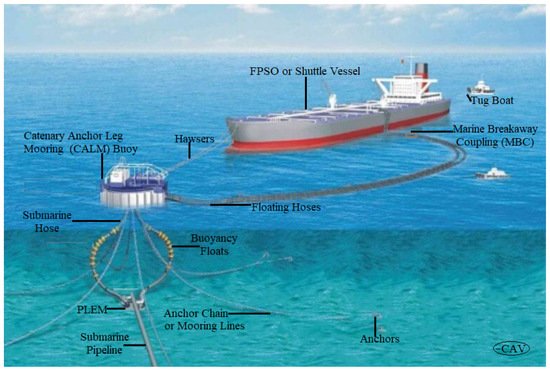
Figure 4. Catenary Anchor Leg Mooring (CALM) Buoy hose system depicting Chinese-Lantern configuration and single point mooring (SPM).
To prepare the mooring for SPM deployment, the following steps are given:
-
For picking up rope, a messenger line has been requested.
-
It must be fitted in an empty drum at the bow, large enough to hold a 120 m [or longer, depending on terminal advice] Pick Up Rope.
-
The messenger must be 100 metres long (or as instructed by the terminal).
-
The messenger should be 1”−3” wide, and at its end have one small shackle.
-
The afterdeck specification to be used on the Tug Boat should be 02 × 200 Mt.
3. Model Application of Bonded Marine Hoses
Bonded marine hoses are for loading and offloading purposes. These hoses are used in a wide range of mooring systems. The circumstances under which they must operate also differ based on environmental conditions, size of the oil well, the water depth, the capacity of the terminal, the amount of hoses, the sizes of the hoses, the number of mooring chains (or mooring lines), the number of shuttle vessels, the schedule of daily operation, and the designed (un)loading system. Even within a single system, there are differences in the specifications of the many segments that make it up.
3.1. Configurations for Submarine Hoses
3.1.1. CALM Buoy Hose Configurations
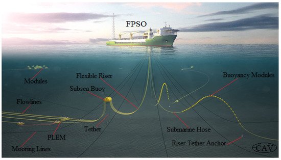
The Catenary Anchor Leg Mooring (CALM) buoy system comprises a buoy with pivot, called the turntable. Sometimes, it is called the turret buoy or turntable buoy. Figure 4 shows the different configurations of Catenary Anchor Leg Mooring (CALM) buoy systems. The CALM buoy system has different connections, such as the mooring fairlead and hose manifold. The tanker is anchored to the turntable pivot, as it rotates around its vertical axis. The turntable is also connected to the floating hose through the hose manifold at an angle. The tanker is attached to the turntable and connected to the turntable’s floating hose strings. The mooring chains or anchor chains are used to moor the buoy as it aids in the buoy’s stability. A swivel transfers the fluid to the submarine hose strings connected to the undersea pipeline via the pipeline end manifold. The entire system can freely spin due to the forces applied by currents and waves, a phenomenon known as weathervaning. Figure 5 depicts an internal turret FPSO with multiple arrangements of marine hoses and flexible risers on an FPSO.
Figure 5. An internal turret FPSO with multiple marine hoses and flexible risers showing different configuration and the following components: modules, flowlines, flexible riser, subsea buoy, tether, PLEM, mooring lines, submarine hose, riser tether anchor, buoyancy modules and internal turret system.
3.1.2. Chinese-Lantern Hose Configurations
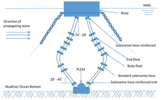
Underwater floats are tied to the hose string, which should keep its shape even under the harshest situations. To avoid concentrated bending strains, the hoses connecting to the pipeline end manifold should be strengthened at the attached end. A typical system for Chinese-lantern hose configuration is given in Figure 6.
Figure 6. An illustration of Chinese-lantern hose configuration.
3.1.3. Lazy-S Hose Configurations
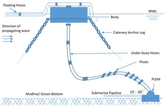
To obtain the optimum hose arrangement, floatation in the form of bead floats or adjustable buoyancy tanks is given. This is done just to avoid kinking or wear upon this hose. A typical system for Lazy-S hose configuration is given in Figure 7.
Figure 7. An illustration of Lazy-S Hose Configuration.
3.1.4. Steep-S Hose Configurations
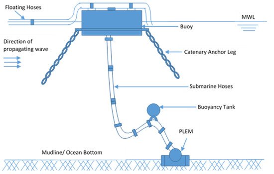
CALM buoys in water depths greater than 45 metres benefit from this design. The buoyancy tanks’ capacity must be sufficient to sustain positive buoyancy for hoses in both oil and water filled conditions. A typical system for Steep-S hose configuration is given in Figure 8.
Figure 8. An illustration of Steep-S hose configuration.
3.2. Configurations for Floating Hoses
3.2.1. SALM Buoy Hose Configurations
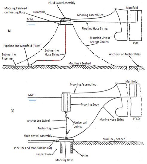
The SALM (Single Anchor Leg Mooring) system consists of a mooring buoy connected to a gravity or piling foundation by an anchor chain with a swivel for rotation, as in Figure 9. The tanker moors with one or more hawsers to the buoy in the CALM system, but the hose strings in the SALM system go directly to the pipeline end manifold. A fluid swivel is positioned concentrically around the anchor leg to allow fluid to pass through while rotating in reaction to the motions of the moored vessel. The fluid swivel is connected to the submarine hose string. The hose arm can be pivoted around the horizontal axis, allowing the angle at which the hose leaves the fluid swivel to vary, or it can be locked at a specific angle. The hose string might be shaped in an S-shape or can vertically and gradually curve towards the horizontal water plane. To achieve the correct shape, buoyancy must be used. Integral floatation or hose floats can be used to accomplish this. Integral floatation, on the other hand, does not work effectively in the presence of a substantial hydrostatic head. Between the submarine and the floating hoses, there must be enough buoyancy to prevent the floating hose from being pulled underwater. To spread the bending stresses caused by the transition between the undersea and floating hoses, hose pieces with reinforced ends must be employed.
Figure 9. Buoy systems showing (a) CALM and (b) SALM buoy systems.
3.2.2. Floating Tandem Mooring Hose Configurations
Tandem mooring is a technique for transporting oil and oil by-products from FSOs, FPSOs, FSUs, FSRUs, and other extraction facilities to shuttle tankers. It can be floating or submerged, and it can be hung from the ship’s side or wound around a reel. A retention rope and revolving spool component secure the string to the vessel, resulting in the “Goose-Neck” design. Depending on the environmental circumstances, a floating or submarine string can be used. In some circumstances, the oil is extracted from the well using a Floating Production Storage and Offloading (FPSO) system. As shown in Figure 10, these ships are anchored with a turret and anchor lines. The arrangement of the tandem mooring given in Table 1 is for the hose positions in Figure 10.
Figure 10. Tandem mooring floating hose configuration.
Table 1. Arrangement of tandem mooring floating hoses.
| No. |
Location |
Description |
Hose Type |
Optional Type |
Characteristics |
Application |
| 1 |
FPSO Connection |
Off take connection |
Floating |
Reel |
Reinforced hose end, at one end |
Connected to shuttle tanker bow loading point or FPSO |
| 2 |
Reduced Buoyancy |
Reducer |
Floating |
Reel |
Reduced buoyancy or Neutral |
Often next to 2–3 hose sections on the string |
| 3 |
Mainline |
Mainline |
Floating |
Reel |
Fairly flexible |
Main part of the floating hose string |
| 4 |
Operational Taper |
Taper |
Floating |
Reel |
Integral reducing bore |
Connection of smaller bore tail hose and larger bore mainline |
| 5 |
Tail |
Tail Hose |
Floating |
Reel |
Electrically discontinuous |
Smaller bore diameter compared to mainline. Links tanker end to handle rail hose |
| 6 |
Rail |
Rail Hose |
Floating Rail |
Reel |
Higher flexibility during lug lifting |
Over rail hose for connecting to the manifolds of conventional midships |
3.2.3. Stored Hose (or Hose Reel) Tandem Mooring
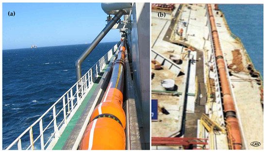
The mooring is done in a tandem configuration once more. However, the hose is employed as an in-air catenary, floating on the water, as shown in Figure 11. When not in use, the offloading hose is stored on the FPSO in a chute (as seen in Figure 11) or on a hose reel (as seen in Figure 12). The goal of the reeling hose configuration is to be able to recover and store the hose on the FPSO during bad weather. Hoses of this type must have a high flexibility reserve, bend radius tolerance, and axial strength. In the event of an emergency release, the catenary design also has intrinsic buoyancy, ensuring that the hose string is not lost, even when filled with water.
Figure 11. Two different hose storage systems in the chutes of floating FPSOs, showing (a) loading hose stowed on deck’s chute along the FPSO’s wall, which could also be a free-hanging catenary hose, and (b) loading hose stowed in the chute on a lower area of FPSO’s deck inside its deck trays between loadings, with the hose string winched onboard over a stern roller chute.
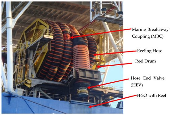
Figure 12. Offshore reeling hose stored on the reel-drum showing reel, Marine Breakaway Coupling (MBC) and Hose End Valve (HEV).
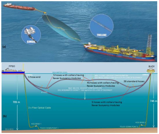
3.2.4. Deepwater Export Lines
Spread mooring is frequently employed instead of a turret mooring system in projects having locations with relatively light environmental conditions. The issue this creates is that, due to the practicalities resulting from the large expanse of seawater required, it consumes more resources. In addition, the FPSO’s fixed position and the tandem mooring with the shuttle tanker make it quite challenging to achieve. Typical materials for such deepwater export lines have been reported by Trelleborg
[16][17][18][19][20]. A deepwater export connection to a CALM buoy, where the shuttle tanker moors, could be one possibility
[18][19][20], as in
Figure 13. The tankers may weathervane here without having to worry about colliding with the FPSO. The hose’s deepest point is generally between 200 m and 300 m deep.
Figure 13. Deepwater Export Line showing (a) typical offloading line (OOL) called Trelleborg’s trelline and gimbal with spread moorings, and (b) Pazflor OOL configuration. It shows the deepwater OOL array used as: 1 hose end, 38 hoses with collars having fewer buoyancy modules, 5 hoses with collars having fewer buoyancy modules, 45 hoses with collars having fewer buoyancy modules, 5 hoses with collars having fewer buoyancy modules, 38 hoses with collars having fewer buoyancy modules (Adapted, Courtesy: Trelleborg).
Abbreviations
| CALM |
Catenary Anchor Leg Mooring |
| FPSO |
Floating Production Storage and Offloading |
| FSO |
Floating Storage and Offloading |
| FSRU |
Floating Storage and Regasification Unit |
| FSU |
Floating Storage Unit |
| HEV |
Hose End Valves |
| MBC |
Marine Breakaway Coupling |
| MBM |
Multi Buoy Mooring (or Multiple Buoy Mooring) |
| OCIMF |
Oil Companies International Marine Forum |
| PLEM |
Pipeline End Manifold |
| SALM |
Single Anchor Leg Mooring |
| SBM |
Single Buoy Mooring |
| SDG |
Sustainable Development Goals |
| SPAR |
Single Point Anchor Reservoir |
| SPM |
Single Point Mooring |
| TLP |
Tension Leg Platform |
| UN |
United Nation |
| |
|
 +1 point