Disposal of palm oil mill effluent (POME), which is highly polluting from the palm oil industry, needs to be handled properly to minimize the harmful impact on the surrounding environment.
1. Introduction
The rapid growth of the palm oil industry worldwide has invited serious water pollution in aquatic systems. Large crude palm oil (CPO) production has resulted in an increase in palm oil mill effluent (POME) generated from the CPO process. Each ton of CPO production produces about 2.5–3.0 m
3 of POME
[1]. Huge amounts of POME with a high concentration of organic content have implications in environmental pollution if not handled properly. POME is declared as one of the most difficult wastes to handle due to its large production and ineffective processing technology.
Fresh POME is generally acidic (pH 3.3–4.6), high in temperature (60–80 °C), thick, brownish in color with solids (1330–50,700 mg/L), with oils and fats (190–14,720 mg/L), a biochemical oxygen demand (BOD) of 8200–35,000 mg/L, and chemical oxygen demand (COD) of 15,103–65,100 mg/L
[2]. Regulations regarding quality standards for the discharge of POME into the environment or water bodies to prevent the negative effects of POME waste have been established. The latest regulations state that the COD and BOD standards were set at lower than 250 mg/L and 100 mg/L, respectively.
The most widely used POME waste treatment is conventional treatment using an open pond system through anaerobic and aerobic decomposition processes. The disadvantage of this system is that apart from requiring a large area of land and a long retention time, it can also emit harmful gases such as methane gas and cause sludge build-up
[3]. Therefore, conventional treatment is very inefficient for treating POME. In recent years, various treatment methods have been developed to eliminate and reduce POME pollution
[3]. These methods include composting
[4], fermentation
[5], coagulation flocculation
[6], adsorption
[7], flotation, membrane technology
[8], steam reforming
[9], and advanced oxidation processes
[10]. Among these technologies, photocatalytic technology is a viable wastewater technology to reduce environmental pollution especially POME waste due to it being eco-friendly, not involving sludge formation and other harmful substances, as well as being cost effective, operated at ambient conditions, and a sustainable process, which addresses the issues of energy consumption and environmental remediation
[11].
TiO
2 is by far the most widely used photocatalyst due to it exhibiting strong oxidizing ability, stability, and high efficiency against organic compounds
[12][13]. However, the main drawback of TiO
2 is its wide band gap (~3.2 eV), which limits its light response to the UV region. As a result, this photocatalyst can only take advantage of less than 6% of the solar energy impinging on the Earth’s surface, and its potential as a sustainable technology cannot be entirely fulfilled
[14]. Therefore, during the last few years an increasingly great number of new photocatalysts have been developed and tested as possible alternatives to TiO
2 based photocatalysts. In this context, the feasibility of using some well-known photocatalysts like bismuth vanadate (BiVO
4) has been reconsidered in light of recent advances in nanotechnology.
BiVO
4 is a less expensive photocatalyst with a narrower band gap (2.4 eV) than TiO
2, which is capable of harvesting visible light for photocatalytic processes
[15][16]. BiVO
4 has been reported to successfully degrade and reduce organic pollutants in wastewater, using methylene blue
[17], rhodamine blue
[18], and methyl orange
[19] as model compounds. The photocatalytic efficiency is closely related to the structure, crystal dimensions, size, morphology, optical band-gap energy, and surface shape. It is also generally considered that the synthesis method and the operating conditions used were the main critical parameters to achieve optimum efficiency removal
[17]. Several studies have been carried out on the synthesis of BiVO
4 with various methods including coprecipitation
[20], hydrothermal
[21], and sol-gel methods
[22]. Among these methods, the sol-gel method is becoming increasingly used because it requires only simple equipment and a low process temperature, compared to the traditional powder method
[17]. However, up to now there has been no research that has developed a BiVO
4 photocatalyst specifically for POME waste treatment.
2. Crystal Phase Composition
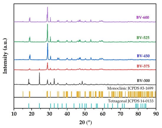
XRD is used to characterize the phase structure of the obtained samples. Figure 1 shows the XRD pattern of the synthesized BiVO4 photocatalyst at different calcination temperatures. Samples are labeled BV-x, where BV and x are attributed to BiVO4 and calcination temperature, respectively. The XRD pattern of BV-300 indicates that the sample is in a mixture of tetragonal and monoclinic phases. The diffraction peaks at 2θ = 18.3; 24.4; 32.7; 34.7; 39.5; 43.8, and 48.4 were attributed to the tetragonal structure of BiVO4 (JCPDS, no. 14-0133). Meanwhile, the diffraction peaks at 2θ = 18.7 and 28.9 were assigned to the monoclinic BiVO4 structure (JCPDS, no. 83-1699). When the calcination temperature was increased to 375 °C (BV-375), a phase change began to occur towards the monoclinic, which can be seen by decreasing the intensity of the tetragonal phase and followed by an increase in intensity in the monoclinic phase. When the calcination temperature increases to 450 °C (BV-450), the tetragonal phase peak disappeared while it predominantly consists of the monoclinic phase. In addition, it generated a sharper XRD pattern, which shows better crystallinity and an increase in crystallite size. Subsequent calcination to temperatures of 525 °C (BV-525) and 600 °C (BV-600) showed that the photocatalysts were all in a monoclinic phase (there were no peaks of tetragonal phase or other impurities were detected).
Figure 1. XRD pattern of BiVO4 photocatalyst with different calcination temperatures.
According to the Zhang et al.
[17], when the calcination temperature was increased up to 400 °C, there were several small peaks at 2θ = 25.7°; 27.7°, and 32.3°, which correspond to Bi
2O
3 being considered an impurity. Increasing the calcination temperature to 450 °C causes the peak corresponding to Bi
2O
3 to disappear. The calcination temperature has a significant impact on the phase composition, degree of crystallinity, and photocatalytic properties of the prepared photocatalyst
[23]. These results indicate that the calcination temperature is an important factor in the preparation of pure monoclinic BiVO
4. The intensity of the XRD diffraction peak of BiVO
4 photocatalyst after calcination at 525 °C was the strongest followed by 450 °C. The narrow and sharp diffraction peaks indicate that the BiVO
4 photocatalyst has high crystallinity. This increase in photocatalyst crystallinity will be advantageous for photocatalytic activity.
On the other hand, the XRD results of the synthesized BiVO
4 photocatalyst are different from Wang et al.
[23], where the calcination was carried out at a temperature range of 350–500 °C for 5 h to produce a crystal structure of BiVO
4 photocatalyst with a pure monoclinic phase structure. In addition, the intensity of the diffraction peak increased with increasing calcination time, indicating that the degree of crystallinity increased with the extension of the calcination time. However, if the calcination time is too long, the monoclinic phase transformed back to a tetragonal phase. In addition, Pookmanee et al.
[24] reported that XRD pattern showed that all BiVO
4 photocatalyst crystals with monoclinic phase structure at the calcination temperature treatment range of 400–600 °C for 2 h. No other phase peaks or impurities were detected. As the calcination temperature increases, the width of the diffraction line decreases and the intensity of the diffraction line increases indicating that a high crystallinity of BiVO
4 photocatalyst was obtained.
The crystal size of the sample was calculated according to the Scherrer formula. The crystal sizes of the BV-300, BV-375, BV-450, BV-525, and BV-600 were 23.79; 21.58; 23.89; 25.68; 26.06 nm, respectively (
Table 1). These results indicate that crystal size increases with increasing calcination temperature in general, which implies that high temperatures favor grain growth stages according to nucleation theory and thermodynamic growth
[23]. However, the BV-375 photocatalyst was inversely proportional due to the phase transformation from the tetragonal phase to the monoclinic phase. The appearance of a broad peak in the BV-375 photocatalyst indicates a decrease in crystal size.
Table 1. Crystallite size and crystallinity percentage of the BiVO4 photocatalyst with different calcination temperatures.
| Photocatalyst |
Crystallite Size (nm) |
Crystallinity (%) |
| BV-300 |
23.79 |
93.9 |
| BV-375 |
21.58 |
52.1 |
| BV-450 |
23.89 |
94.6 |
| BV-525 |
25.68 |
99.4 |
| BV-600 |
26.06 |
89.1 |
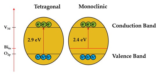
It is known that the monoclinic BiVO
4 crystal structure consists of O 2p and Bi 6s orbitals in the valence band and V 3d orbitals in the conduction band while the tetragonal structure of BiVO
4 consists of only O 2p species in the valence band
[25]. The presence of the Bi6s orbital in the valence band of BiVO
4 is a regulatory factor that helps to improve charge separation and electron-hole pair migration, resulting in better photocatalytic performance (as shown in
Figure 2).
Figure 2. Schematic diagram of BiVO
4 in two different crystal structures, namely tetragonal and monoclinic phases. Adapted from ref.
[25].
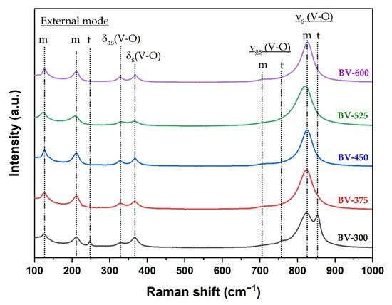
Raman spectroscopy can provide more structural information and is used to support the transformation phase from tetragonal to monoclinic phase by increasing the calcination temperature. The Raman spectrum of the BiVO4 photocatalyst with different calcination temperatures is shown in Figure 3. In the BiVO4 spectrum, the peaks at 827 cm−1 and 854 cm−1 correspond to the symmetrical V-O stretching mode of monoclinic and tetragonal phases, respectively. The weak shoulder peak near 710 cm−1 was designated as the monoclinic V-O asymmetric stretching mode, while the shoulder peak near 755 cm−1 was designated as the tetragonal phase. The double peaks observed at about 328 cm−1 and 366 cm−1 were associated with an asymmetric bending mode (VO4) and a symmetric bending mode (VO4) respectively. The peaks at 126 cm−1 and 210 cm−1 correspond to crystal lattice vibrations for the monoclinic phase while the peak at 247 cm−1 is attributed to the tetragonal phase (external mode). The Raman spectra clearly confirmed the phase transformation from tetragonal to monoclinic phase obtained from XRD measurement (Figure 1) at a calcination temperature of 375 °C (BV-375) indicated by the absence of the peaks at 247, 755, and 854 cm−1.
Figure 3. Raman spectra of the BiVO4 samples synthesized at different calcination temperatures where m and t are attributed to the monoclinic and tetragonal phases, respectively.
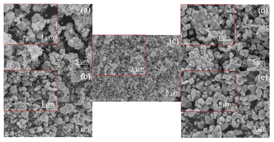
3. Morphology
The morphology of the BiVO
4 photocatalyst was investigated by SEM and TEM, as shown in
Figure 4 and
Figure 5. The tendency of agglomeration in the BiVO
4 photocatalyst occurred more extensively at a low calcination temperature (BV-300) and high calcination temperature (BV-600) compared to the calcination temperature of 450 °C (BV-450). The average particle sizes for BV-300, BV-375, BV-450, BV-525, and BV-600 photocatalysts were 0.759, 0.429, 0.154, 0.425, and 0.709 µm, respectively. Based on
Figure 4, with an increase in the calcination temperature up to 450 °C, the particle size decreased, while beyond that, the particle size gradually increased. The average particle size of the BV-600 photocatalyst from this study exhibited a similar size to the work reported by Pookmanee et al.
[24]. Moreover, it was also revealed that uneven distribution of grains and shapes was observed in BV-300 and BV-375. When the calcination temperature rises up to 450 °C (BV-450), although the agglomeration phenomenon slightly occurs, the grain size is small and has a uniform distribution. The grains become larger at higher temperatures, providing sufficient energy leading to agglomeration. At a calcination temperature of 600 °C (BV-600), the resulting smaller grains gradually begin to melt and reform into larger particles. This phenomenon is in line with the “big eat small” phenomenon in the material sector. Morphological changes in this study are in accordance with the work reported by Wang et al.
[18].
Figure 4. SEM image of the photocatalyst of BiVO4 photocatalysts: (a) BV-300, (b) BV-375, (c) BV-450, (d) BV-525, and (e) BV-600.
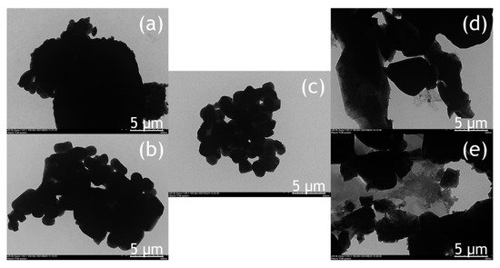
Figure 5. TEM image of the photocatalyst of BiVO4 nanoparticles: (a) BV-300, (b) BV-375, (c) BV-450, (d) BV-525, and (e) BV-600.
The TEM image (Figure 5) provides a clearer visualization of the morphology of the BiVO4 photocatalyst at different calcination temperatures. The BV-450 photocatalyst mainly consisted of small granules, while BV-300, BV-375, BV-525, and BV-600 exhibited irregular shapes. The estimated size of the BV-450 photocatalyst showed predominantly particles with sizes around 150 nm. The good morphology of BV-450 shows the feasibility of these nanostructures for photocatalytic applications.
The atomic compositions of the BiVO
4 photocatalyst were further studied by energy-dispersive X-ray spectroscopy (EDX) and the corresponding results are shown in
Table 2. For all photocatalysts obtained at different calcination temperatures, it consisted of Bi, V, and O with various composition percentages while no additional elements were detected, indicating that the chemical composition of the synthesized BiVO
4 exhibited good product crystallinity. In addition, EDX analysis was carried out to ensure the consistency of the Bi/V ratio between the starting material and the final product within the error range of the experiment. The atomic ratio of the Bi/V trend fluctuated at different calcination temperatures, indicating that the size of the BiVO
4 nanoparticles is not uniform and agglomeration occurs occasionally, which was also confirmed by TEM analysis (
Figure 5). These results are also in line with those reported in previous studies
[26]. In addition, the alteration of the Bi/V ratio indicated lattice distortion and thus generating defect sites on the bulk and/or surface of BiVO
4 photocatalyst
[27].
Table 2. Atomic composition quantification using EDX analysis of the BiVO4 photocatalyst with different calcination temperatures.
| Photocatalyst |
Atomic, % |
Bi/V Ratio |
| Bi |
V |
O |
| BV-300 |
22.71 |
34.70 |
42.59 |
0.65 |
| BV-375 |
21.75 |
29.62 |
48.63 |
0.73 |
| BV-450 |
15.57 |
27.71 |
54.72 |
0.56 |
| BV-525 |
21.90 |
30.39 |
47.71 |
0.72 |
| BV-600 |
22.68 |
33.73 |
43.60 |
0.67 |
 +1 point