1000/1000
Hot
Most Recent
 +1 point
Thermoelectric generators (TEGs) are a form of energy harvester and eco-friendly power generation system that directly transform thermal energy into electrical energy. The thermoelectric (TE) method of energy harvesting takes advantage of the Seebeck effect, which offers a simple solution for fulfilling the power-supply demand in almost every electronics system. A high-temperature condition is commonly essential in the working mechanism of the TE device, which unfortunately limits the potential implementation of the device.
The pursuit of new renewable energy options, as well as preserving a sustainable energy system, have become a global priority. Energy harvesting is the process of harnessing energy from available resources and subsequently converting it to electricity [1]. In the absence of the main energy source, harvested energy is typically used to operate small and medium-sized computer devices, as well as electrical systems, with power production varying from nW to hundreds of mW [2][3]. It must be considered that the main aim of energy harvesting is not to produce power at a large scale, but to capture the wasted energy, put in storage, and use it later for the daily operation of micro- and nanoelectronic systems
Examples of energy harvesters’ concepts are based on the photoelectric effect [4] and electromagnetic [5][6], piezoelectric [7][8][9], and radio-frequency harvester mechanisms [10][11]. Among all energy-harvester devices, TEGs have received extensive attention due to their ability to interconvert heat and electricity [12], as well as their large potential energy availability [13][14] and versatile application [15][16]. This allows TE to play a prominent role as a renewable energy source by repurposing excess heat from the environment [17][18].
A TE energy harvester, which can generate electricity, has a lot of advantages, including the following: usage as an extremely durable and lightweight solid-state system, while being maintenance-free, silent, and environmentally friendly, since heat is harvested from normally wasted heat sources and converted to electricity; a high-temperature process (up to 250 °C); and scalable applications that are capable of harvesting large quantities of energy when required. Additionally, power can be harvested from hot or cold surfaces [19]. Furthermore, a TEG unit generates usable renewable electricity without consuming fossil fuels, resulting in a decrease in greenhouse gas pollution and therefore ecofriendly. Due to these numerous advantages, TE technology remains highly competitive.
TE phenomena are exhibited in almost all conducting materials. Since the figure of merit is temperature-dependent, a more precise measure of performance is the dimensionless figure of merit ZT, where T is the absolute temperature. Only materials with a 0.5 ZT are commonly considered as TE materials [20]. To produce sufficient power, a TE generator must be efficiently used across a large temperature difference ΔT = Th− Tc(Th= temperature of hot side, Tc= temperature of cold side).
The ZT values of some common commercially used materials are shown in Figure 1. These materials can be divided into three groups based on the working temperature range:
(1)Low-temperature materials, in which the working temperature is around 400 K. Alloys based on bismuth are among the popular materials in this temperature region [21].
(2)Intermediate-temperature materials, in which the working temperature is between 600 and 900 K. Alloys based on lead are commonly used in this category.
(3)High-temperature materials, in which the working temperature is higher than 900 K. Material fabricated from silicon– germanium usually falls under this region [18].
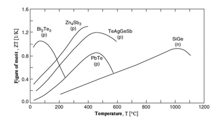
Figure 1.ZTs of common TE materials for p- and n-types. Reprinted with permission from [22].
In 1821, German physicist Thomas Johann Seebeck discovered heat conversion into electricity when two different metals at different temperatures were applied between junctions. This phenomenon is known as the Seebeck effect. Today, TEGs apply the Seebeck effect to convert heat into electricity [23].
The basic principle of a TEG is the production of electromotive force (EMF) across a material when temperature differences are available. Here, the voltage difference produced between the two metal junctions is proportional to the temperature difference.
The TEG is a solid-state heat engine made of two semiconductor materials with primary junctions, known as the n-type and p-type. Then-type elements are doped to contain a highly concentrated negative charge or electron, while the p-type element is doped to make it into a high-quantity positive charge, or holes. The elements with a high number of electrons will provide a negative Seebeck coefficient. On the other hand, elements with a high number of holes contribute to a positive Seebeck coefficient [24].
A TEG is basically made up of one or more TE couples. The most basic TEG is a thermocouple, which comprises a pair of p- and n-type TE materials, electrically bound in series and thermally bound in parallel. An electrical conductor, normally a copper strip, connects the two legs to one side, creating a junction [25].
As the temperature between the junction changes, the electron at the end of the n-type material closest to the heat source gains energy. At the end of the n-type element closest to the heat source, the electron concentration is greater than at the end of the cold side. The electron at the heat source end will move to the cold side end, similar to how heat travels from a hot region to a cold region [26]. The same applies to the holes in the p-type elements.
When a potential load exists, the movement of electrons and holes in an n- or p-type element induces the EMF, which results in electrical current production. As long as a temperature gradient between the two junctions exists, current will be produced. More electric output power is produced as the temperature gradient, ΔT = Th− Tc, across the TEG unit rises.
The formation of EMF in a pair of n- and p-type elements is minimal. Consequently, many such TE couples are needed to obtain a high enough voltage. Several TE couples are electrically linked in series and sandwiched between two ceramic sheets [27].
A TEG is a heat engine [20]. Therefore, efficiency is the most influential parameter for indicating device performance. The efficiency of the TEG is described as the ratio of the electrical power supplied to the load versus the heat absorbed at the hot junction if the converter is used as an ideal generator with no energy loss. For a TEG operating between a heat source at high temperature, Th, and a heat sink at low temperature, Tc, the TEG efficiency is given by [28]:
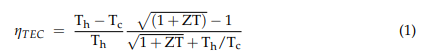
As can be seen in Equation (1), the efficiency of TEG is highly dependent on the temperature gradient between the junctions, the TEG operating temperatures, and the ZT value. The ηTEG proportionally increases as the temperature gradient between the junctions, ΔT, increases. For TEGs at low operating temperatures, 25% of the ηTEG can be reached if only materials with ZT = 10 are obtainable [22].
At the beginning of the 20th century, the advancement of TE materials began. Altenkirch suggested a dimensionless figure of the ZT value, called the figure of merit, to indicate the TE material`s efficiency
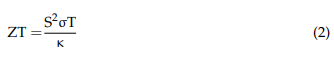
where S is the Seebeck coefficient determined by the ratio of the EMF produced to the temperature difference. In addition, σ is the electrical conductivity in S/cm, κ is the thermal conductivity (including lattice component kp and electronic component ke) in W/mK, and T is the absolute temperature in K [28].
The Seebeck effect is the EMF produced across a material in which temperature differences are present. The Seebeck effect, S, is the ratio of the EMF produced to the temperature difference. The S of an intrinsic semiconductor (undoped semiconductor) is determined by the partial S of the electrons and holes, weighted by their conductivities, according to the relation:
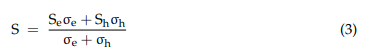
where Se is the Seebeck component due to n-type carrier conduction, Sh is the Seebeck component due to p-type carrier conduction, σe is the electrical conductivity by n-type carriers, and σh is the electrical conductivity by p-type carriers.
Here, ZT is a material property. Enhancing the ZT value will improve the efficiency of a TE material. In order to obtain it, the numerator in Equation (2), S2σ, which is also called a “power factor” (PF), needs to be maximised. In the ZT equation, T is the temperature in Kelvin where all the property is being measured at that particular temperature, with small changes applied to determine Z.
This ideal material posses a physical property that would scatter phonons, reducing the lattice contribution to κ as if in glass, but at the same time allowing electrons to move easily through the material, as they would in a crystal. Heat is transferred in solids through atomic lattice vibrations. Chemical bonds hold the atoms in solids together in a lattice configuration. These bonds are not rigid; rather, they behave like a spring, connecting the atoms through a spring–mass mechanism. As an atom or a plane of atoms displaces, the displacement will spread through the crystal as a wave, carrying energy with it. These waves are quantised and are known as phonons [29].
The greatest need for new TE materials is at low operating temperatures. TE operating in a low-temperature area is highly needed for recycling low-grade waste heat. According to [30], for TE working at near-room temperature, for the material required to have a combination of high ZT, low κ, and high S, unlike TE working at intermediate or high temperature, the low value for κ is not essential. Thus, there is a motivation to improve the material properties to enhance the TE performance in this temperature region.
Currently, there is no bulk material with a high enough TE efficiency to reach a practical level in the low-temperature region below 250 K. As a result, there is a drive to upgrade material properties in an attempt to optimise TE efficiency in this temperature range. To achieve such high efficiency, improving the PF and S = σS2 of a material, where S and σ are the TE power and σ, respectively, is the first step. A target value of PF is ~35 μWcm−1K−2, which is the typical value of Bi2Te3-based practical materials [31]. Several candidate materials working at low operating temperatures, such as Bi2Te3, CsBi4Te6, AgSbTe2, and MgAgSb, have been developed thus far.


