1000/1000
Hot
Most Recent
 +1 point
Due to the societal ambition regarding an accelerated energy transition in several electrical power systems worldwide, a progressive technological upgrade (i.e., massive deployment of different types of power electronic converters) is taking place, occurring more prominently in the generation mix. To date, several studies have envisioned or are currently investigating futuristic topologies and operating conditions with shares from decoupled renewable power generation (e.g., type-IV wind turbines) equal to or higher than 50%. One expected issue of high concern that is an intensive research focus of this upgrading is the degradation of the time-varying frequency excursions occurring in the frequency containment period, especially when large active power imbalances occur .
Due to the societal ambition regarding an accelerated energy transition in several electrical power systems worldwide, a progressive technological upgrade (i.e., massive deployment of different types of power electronic converters) is taking place, occurring more prominently in the generation mix. To date, several studies have envisioned or are currently investigating futuristic topologies and operating conditions with shares from decoupled renewable power generation (e.g., type-IV wind turbines) equal to or higher than 50% [1][2][3]. One expected issue of high concern that is an intensive research focus of this upgrading is the degradation of the time-varying frequency excursions occurring in the frequency containment period, especially when large active power imbalances occur [4]. Specifically, undesirable values of RoCoF and the nadir occur within a few ms from the time of occurrence of an active power imbalance without the incorporation and action of FAPR on sources that can eventually provide dynamic frequency support [4][5][6][7].
An FAPR control strategy is theoretically expected to adjust the active power output in less time than the typical timeframe of reaction by governor systems attached to conventional power plants. This feature has been acknowledged in several recent publications as a preferred means for quickly bound dynamic frequency deviations. The FAPR control strategies selected for study in this paper can use one of the following three options: (i) droop-based (proportional) strategies depending on measured instantaneous frequency deviations [8][9][10][11]; (ii) frequency derivative-based strategies [12][13][14]; and (iii) virtual synchronous power (VSP) strategies. Each strategy can be customized to perform based on measured instantaneous frequency deviations or measured instantaneous variations of active power imbalances [15][16][17][18][19].
Current efforts are directed towards the use of advanced simulation and co-simulation techniques for the offline study and design of the above-indicated FAPR strategies for power electronic energy-based generation. The urgent need for this versatility has been pointed out in several publications, and is related to the need to extensively use PHIL in the research of power electronic converter-dominated electrical power systems [20][21][22]. The detailed modeling and simulation of the studied system is done based on the advanced functionalities of RTDS. In addition to the useful information that the proposed PHIL setup provides regarding the performance of FAPR strategies, it also decreases the period of simulation development (i.e., low latency, in the order of a few ms), prevents simulation inaccuracy, and decreases the risk of practical implementation (e.g., there is no need for interfacing through analogue/digital cards).
The proposed PHIL setup is illustratively represented in Figure 1. The setup involves the following components:
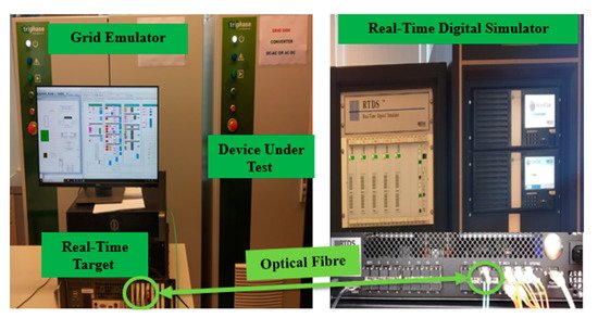
Figure 1. Developed PHIL setup.
NovaCor chassis of the RTDS [17] : This is a high-performance multicore processor used for the modeling and real-time simulations of power electronic converted dominated power systems. Additionally, the Aurora protocol is applied to provide a communication interface between the chassis and the RTT, which are linked through a dedicated optical fiber.
Real-time target (RTT): This element constitutes a PC-based (multi-core) module working with a real-time operating system (e.g., Linux/Xenomai). It is used to enable the exchange of signals between the NovaCor chassis and the actual hardware used (i.e., for grid emulation and DUT). The studied FAPR control strategies are programmed in the RTT.
Grid Emulator: This component has a back-to-back layout, comprising a so-called front-end converter unit (to regulate the DC voltage) and a VSC unit that is used to create dynamic signals (i.e., time-varying waveforms of smaller amplitude) that resemble the simulated instantaneous waveforms (e.g., voltage, currents) obtained by using the NovaCor chassis.
This is a small-sized (15 kW) VSC which can represent the grid side converter of a decoupled (type-IV) WT. The FAPR is programmed in the RTT and acts on the DUT in real time. The inner and outer controllers of this DUT can be modified and tuned to resemble the generic models used in the NovaCor chassis. Therefore, this component is used in this paper to quantitatively corroborate the findings from pure software-based (RSCAD) simulation studies.
The real-time EMT representation of the studied system is performed in RSCAD [19] and runs in NovaCor, which can be interfaced with external physical devices (e.g., DUT).The control strategies to subordinate the grid emulator and the DUT are implemented using the RTT. The RTT and NovaCor exchange signals (e.g., waveforms of voltages and currents) through an optical fiber. The Simulink model has blocks to perform write/read bus definitions. The VSC (DUT), which is connected to grid emulator with virtual PCC conditions injects active power based on the modulated active current reference (Id_ref).
The real-time EMT representation of the studied system is performed in RSCAD [19] and runs in NovaCor, which can be interfaced with external physical devices (e.g., DUT).
The control strategies to subordinate the grid emulator and the DUT are implemented using the RTT. The implementation is done through a combined environment of Triphase (Triphase Technologies, Bangalore, India) and Matlab/Simulink (MathWorks, Natick, MA, USA). The RTT and NovaCor exchange signals (e.g., waveforms of voltages and currents) through an optical fiber.
The RTDS sends setpoints to RTT. These setpoints govern the instantaneous voltage of the grid emulator as well as the setpoints for the output current of the DUT.
The Aurora protocol is applied for the bidirectional transfer of information between RTDS and the RTT. This facilitates the exchange of information of simulations from Matlab/Simulink control and signal processing models that are compiled in the RTT. The Simulink model has blocks to perform write/read bus definitions. It should be ensured that the same bus name previously defined as the input/output bus name is used in the write/read blocks.
The simulated instantaneous voltage from the system model running in RSCAD-RTDS is given to the RTT to reproduce the desired voltage waveform (with the same frequency but with smaller amplitude) at the AC side (i.e., the point of interconnection of the DUT) of the VSC of the grid emulator.
Since the RTDS and the RTT run simultaneously in real time, there exists the freedom to choose RSCAD or Simulink to implement each of the selected FAPR strategies. The current reference signals are affected by the implemented FAPR strategies. The VSC (DUT), which is connected to grid emulator with virtual PCC conditions injects active power based on the modulated active current reference (Id_ref).
The selected FAPR control strategies are briefly presented in this section. Among the selected strategies are the:Droop-based FAPR strategyDroop-derivative-based FAPR strategyVSP-based FAPR strategy
Droop-based FAPR strategy
Droop-derivative-based FAPR strategy
VSP-based FAPR strategy
The input f constitutes the measured signal of time-varying frequency at a point of interface between the power plant and the system. The PMU is used to measure the frequency; it is taken from the RSCAD library. The PMU block is composed of a low-pass filter, sampling circuit, time-synchronized signal, and processing unit. The estimated phasor value consists of the magnitude, phase, frequency, and rate of change of frequency of its input signal.
The signal Δf is amplified by Kp. The output signal ΔPref of FAPR is a supplementary signal attached to the other active power control loop of a grid side converter. ΔPre performs exclusively when an active power imbalance occurs in the system. The drawback of the droop-based FAPR strategy resides in the slow initial response, which could be attributed to low frequency error values.
The actuation of the droop controller is active for the entire frequency curtailment period. The second loop is a derivative control, whose output is a derivative gain of the frequency error signal. The derivative controller is active only for the initial few seconds and lasts until the frequency signal reaches the maximum allowed frequency deviation. The combined effect of the outputs of the droop-based loop and derivative-based loop produces ΔPref, which modulates the active power response of the WT to improve both the RoCoF and maximum frequency deviation (e.g., the nadir).
The droop derivative FAPR strategy should be tuned (taking into account system-dependent dynamic properties) to cause a prominent ramping of the active power output at the AC side of a grid side converter whenever an over/under-frequency event occurs.
Figure 2 depicts the VSP controller, which measures the power required at the PCC to the reference power available at the bus. In this control scheme ζ is a damping coefficient, and ωn constitutes the natural frequency for implementing this second-order function.
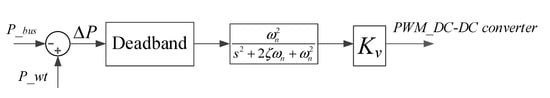
Figure 2. Block diagram of a VSP-based FAPR control strategy.
As shown in Figure 3, the power going out from the node bus (P_bus) reacts to the grid when there is a load disturbance, whereas P_wt will not be instantaneously altered. This difference will be taken as error, ΔP, in the VSP control block (cf., Figure 2), which is further passed through a dead-band block, and later through a second-order transfer function. The output of this block defines the duty cycle of a PWM controller. Hence, the limits of this block are between 0 and 0.9.
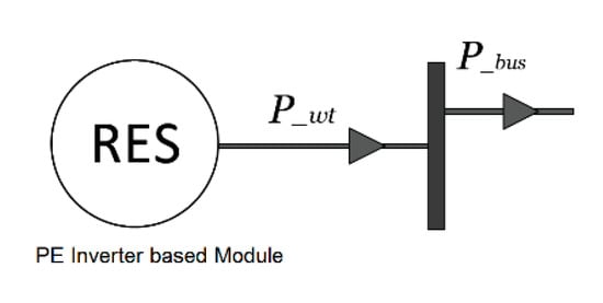
Figure 3. Connection of a decoupled WT to the system, indicating the inputs for VSP-based FAPR.
Figure 4 describes the connection diagram of a battery power management system (BPMS), which has a battery energy storage system (BESS), and a DC-DC converter that operates bi-directionally. The storage is used to inject active power to emulate the inertia. The function of machine side converter is to convert the variable AC power generated by the wind turbine into the DC power. It also tracks the maximum power point of wind-generated power.
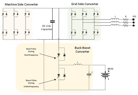
Figure 4. Circuit diagram of a VSP-based BPMS.


